Hydraulic System
AssemblyOpen-centre hydraulics with twin variable-displacement main pumps. A full specification article for this item is being written. Meanwhile its bill of materials and connections are below.
Hydraulic System parts and their functions
19 top-level parts · 1,540 parts in total · full bill of materials below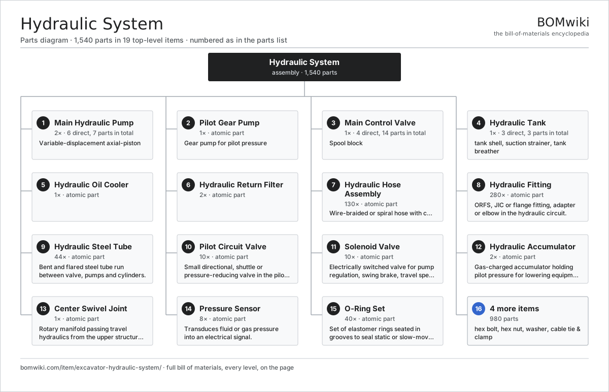
| # | Part | Qty | What it does |
|---|---|---|---|
| 1 | Main Hydraulic Pump 6 parts | 2× | Variable-displacement axial-piston |
| 2 | Pilot Gear Pump | 1× | Gear pump for pilot pressure |
| 3 | Main Control Valve 4 parts | 1× | Spool block |
| 4 | Hydraulic Tank 3 parts | 1× | |
| 5 | Hydraulic Oil Cooler | 1× | |
| 6 | Hydraulic Return Filter | 2× | |
| 7 | Hydraulic Hose Assembly | 130× | Wire-braided or spiral hose with crimped fittings, one run in the hydraulic circuit. |
| 8 | Hydraulic Fitting | 280× | ORFS, JIC or flange fitting, adapter or elbow in the hydraulic circuit. |
| 9 | Hydraulic Steel Tube | 44× | Bent and flared steel tube run between valve, pumps and cylinders. |
| 10 | Pilot Circuit Valve | 10× | Small directional, shuttle or pressure-reducing valve in the pilot circuit: travel pedal valves, pilot manifold and lock valve. |
| 11 | Solenoid Valve | 10× | Electrically switched valve for pump regulation, swing brake, travel speed and attachments. |
| 12 | Hydraulic Accumulator | 2× | Gas-charged accumulator holding pilot pressure for lowering equipment with the engine off. |
| 13 | Center Swivel Joint | 1× | Rotary manifold passing travel hydraulics from the upper structure to the undercarriage through the slew ring. |
| 14 | Pressure Sensor | 8× | Transduces fluid or gas pressure into an electrical signal. |
| 15 | O-Ring Set | 40× | Set of elastomer rings seated in grooves to seal static or slow-moving joints against fluid and gas, sized to ISO 3601. |
| 16 | Hex Bolt | 360× | Flanged hex bolt, M8 to M24, used throughout the structure, covers and equipment mounts. |
| 17 | Hex Nut | 200× | Flanged or nyloc hex nut mating the bolts. |
| 18 | Washer | 200× | Flat or spring washer under bolt heads and nuts. |
| 19 | Cable Tie & Clamp | 220× | Tie, P-clip or saddle clamp securing wiring, hoses and lines to the structure. |
3D model
No 3D model yet. Have a CAD file of this? Add a 3D model. STL renders right on this page; STEP, FreeCAD, and OpenSCAD sources are welcome too (openly licensed, like all 3D models on BOMwiki).
Build & assembly graph
expand / collapse · shared sub-assemblies converge · links to related products · est. labour
product / assembly
shared across products
atomic part
related product
Tap an assembly to expand/collapse · tap a part to open it · use “Open page” for any node · drag to pan, scroll to zoom.
Bill of materials for Hydraulic System
19 top-level lines · 32 rows shown · 1,540 parts total · indented to 3 levels| # | Item / sub-assembly | Part no. | Qty/assy | Ext. qty | Parts | Type |
|---|---|---|---|---|---|---|
| 1 | Main Hydraulic Pump 6 parts | excavator-main-hydraulic-pump | 2× | 2 | 7 | assembly |
| 1.1 | Pump Rotating Group | excavator-pump-rotating-group | 1× | 2 | · | part |
| 1.2 | Swash Plate | excavator-swash-plate | 1× | 2 | · | part |
| 1.3 | Pump Regulator | excavator-pump-regulator | 1× | 2 | · | part |
| 1.4 | Ball Bearing | ball-bearing | 2× | 4 | · | part |
| 1.5 | Oil Seal | oil-seal | 1× | 2 | · | part |
| 1.6 | O-Ring Set | oring-set | 1× | 2 | · | part |
| 2 | Pilot Gear Pump | excavator-pilot-pump | 1× | 1 | · | part |
| 3 | Main Control Valve 4 parts | excavator-main-control-valve | 1× | 1 | 14 | assembly |
| 3.1 | Spool Block Casting | excavator-spool-block | 1× | 1 | · | part |
| 3.2 | Control Spool | excavator-control-spool | 8× | 8 | · | part |
| 3.3 | Relief Valve | excavator-relief-valve | 4× | 4 | · | part |
| 3.4 | O-Ring Set | oring-set | 1× | 1 | · | part |
| 4 | Hydraulic Tank 3 parts | excavator-hydraulic-tank | 1× | 1 | 3 | assembly |
| 4.1 | Tank Shell | excavator-tank-shell | 1× | 1 | · | part |
| 4.2 | Suction Strainer | excavator-suction-strainer | 1× | 1 | · | part |
| 4.3 | Tank Breather | excavator-breather | 1× | 1 | · | part |
| 5 | Hydraulic Oil Cooler | excavator-oil-cooler | 1× | 1 | · | part |
| 6 | Hydraulic Return Filter | excavator-hydraulic-filter | 2× | 2 | · | part |
| 7 | Hydraulic Hose Assembly | excavator-hydraulic-hose | 130× | 130 | · | part |
| 8 | Hydraulic Fitting | excavator-hose-fitting | 280× | 280 | · | part |
| 9 | Hydraulic Steel Tube | excavator-hydraulic-tube | 44× | 44 | · | part |
| 10 | Pilot Circuit Valve | excavator-pilot-circuit-valve | 10× | 10 | · | part |
| 11 | Solenoid Valve | excavator-solenoid-valve | 10× | 10 | · | part |
| 12 | Hydraulic Accumulator | excavator-accumulator | 2× | 2 | · | part |
| 13 | Center Swivel Joint | excavator-center-joint | 1× | 1 | · | part |
| 14 | Pressure Sensor | pressure-sensor | 8× | 8 | · | part |
| 15 | O-Ring Set | oring-set | 40× | 40 | · | part |
| 16 | Hex Bolt | excavator-hex-bolt | 360× | 360 | · | part |
| 17 | Hex Nut | excavator-hex-nut | 200× | 200 | · | part |
| 18 | Washer | excavator-washer | 200× | 200 | · | part |
| 19 | Cable Tie & Clamp | excavator-cable-tie | 220× | 220 | · | part |
Something wrong in this list? Report a problem with this BOM.
Where the hydraulic system is used
1 product across 1 domain contain it, directly or inside a sub-assemblyUsed in 1 assembly
Sourcing: possible vendors
Browse the supplier directory → Prices, MOQ, and lead times are algorithmic estimates, not quotes, and not claims about these companies. Company mappings are curated by keyword; est. price band $5–$2k. How estimates work| Vendor | HQ | Specialty | MOQ | Lead time |
|---|---|---|---|---|
| kbl.co.in ↗ | Pune, IN | Pumps & fluid systems | 200 units | 6–10 wks |
| leo.com.cn ↗ | Taizhou, CN | Pumps | 200 units | 6–10 wks |
| shaktipumps.com ↗ | Pithampur, IN | Pumps | 200 units | 6–10 wks |
| cnppumps.com ↗ | Hangzhou, CN | Pumps | 200 units | 6–10 wks |
| rotopumps.com ↗ | Noida, IN | Pumps | 200 units | 6–10 wks |