Contact Plate Freezer
ProductOverview
The contact plate freezer freezes packaged or bulk product by pressing it between hollow refrigerated plates. Instead of blowing cold air over the product as belt and tunnel freezers do, it removes heat by direct conduction: each block sits flat against a metal plate chilled to about -40C, so heat flows straight out through both faces. This is the fastest method for regular-shaped blocks and produces dense, flat, uniform blocks that stack and ship efficiently.
Plate freezers are standard for fish fillets, shrimp, meat, vegetables, and ready meals packed in cartons or trays. They come in two layouts: horizontal, where plates stack like shelves and product loads in from the front, and vertical, where plates stand on edge to form pockets that fill with bulk product such as whole fish or shrimp directly from the catch. Both share the same principle of clamped plate contact.
Plate Stack
The Plate Stack is where freezing happens. Each Contact Plate is a hollow extruded aluminum panel with internal channels carrying refrigerant, so its whole surface stays near -40C. Product blocks sit in the gaps between plates. Plate Spacer spacers set that gap and therefore the finished block thickness, typically 25 to 130 mm; thicker blocks freeze more slowly because heat has farther to travel. The plates slide along Plate Guide Rail rails as the stack opens and closes, with Plate Stop stops limiting travel and Edge Bar bars containing the block edges so blocks form to a clean shape.
Hydraulic Clamping
Good contact is everything in a plate freezer: an air gap of even a millimeter between plate and product slows freezing badly. The Hydraulic System presses the whole stack together so every plate sits flat against its blocks. Hydraulic Cylinder cylinders, fed by the Hydraulic Power Unit and its Hydraulic Pump, clamp the stack at 1-3 bar of contact pressure, controlled by Hydraulic Valve directional valves and read on a Pressure Gauge with Pressure Sensor feedback. The same hydraulics open the stack for loading and unloading. Cylinder and valve seals come from an O-Ring Set, and high-pressure Hydraulic Hose hoses carry the oil.
Refrigeration Supply
The Refrigeration Supply supply gets cold refrigerant into every plate evenly. A Liquid Manifold feeds liquid refrigerant to the plates and a Suction Manifold collects the vapor returning from them, with flow set by an Expansion Valve and shut off by a Solenoid Valve. Ammonia and CO2 are common in marine and large land plants. A Pressure Sensor on the suction side feeds the controller so plate temperature stays in the freezing band.
A second refrigerant function is release. Frozen blocks bond to the cold plates and will not drop out on their own. The Defrost Valve briefly routes hot gas through the plates to warm the surface a fraction of a degree, which breaks the ice bond so the blocks release cleanly when the stack opens.
Flexible Hoses
Because the plates move apart and together every cycle while the manifolds stay fixed, the connection between them cannot be rigid pipe. The Flexible Hose Set set solves this. Each plate connects to the manifolds through braided stainless Flexible Refrigerant Hose hoses with swivel Hose Fitting ends that flex through thousands of open-close cycles without fatigue cracking, protected by Hose Guard guards against pinching. Hose reliability is a common maintenance focus, since a single leaking hose can take a plate offline.
Frame, Cabinet, and Loading
The clamp load is large, so the Frame and Cabinet is built heavy. The welded Main Frame reacts the full hydraulic clamping force without flexing, which would open contact gaps. Horizontal units add an Insulated Cabinet with a Cabinet Door to keep the cold in and a Drip Tray for meltwater, all on adjustable feet.
The Loading System keeps blocks square against the plates. Product Tray trays or frames hold each block to a consistent shape, Tray Guide guides align them in the stack, and a Loading Cart speeds the manual load and unload that horizontal plate freezers still rely on.
Control and Operation
The Control System system runs the cycle from a PLC and Operator HMI touchscreen. A typical cycle clamps the loaded stack, runs the Cycle Timer for the set freeze time of 1.5 to 4 hours while Temperature Sensor probes watch plate and product temperature, then triggers hot-gas release and opens the stack for unloading. Relay contacts switch the hydraulics and refrigerant valves through a Wire Bundle loom.
The plate freezer trades the continuous flow of belt and tunnel freezers for higher heat-transfer efficiency and a denser block. It runs as a batch: load, freeze, unload, repeat. For regular blocks of fish or meat headed for cold storage and later processing, the dense flat format and the low energy per kilogram make contact plate freezing the standard choice.
Contact Plate Freezer parts and their functions
7 top-level parts · 204 parts in total · full bill of materials below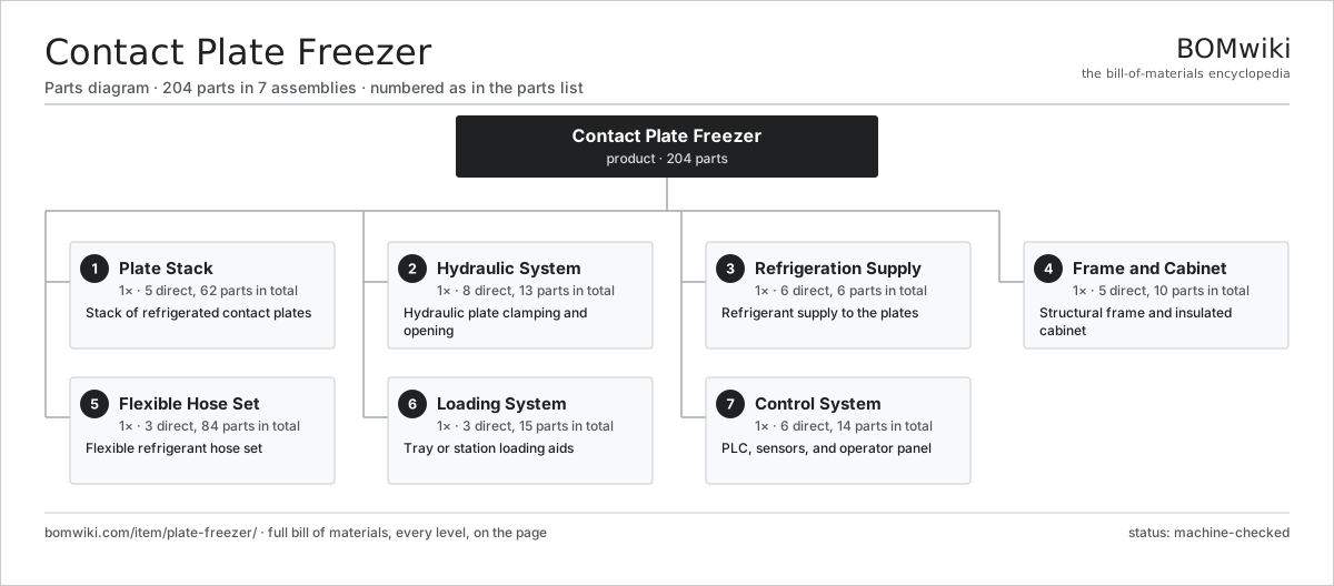
| # | Part | Qty | What it does |
|---|---|---|---|
| 1 | Plate Stack 5 parts | 1× | Stack of refrigerated contact plates |
| 2 | Hydraulic System 8 parts | 1× | Hydraulic plate clamping and opening |
| 3 | Refrigeration Supply 6 parts | 1× | Refrigerant supply to the plates |
| 4 | Frame and Cabinet 5 parts | 1× | Structural frame and insulated cabinet |
| 5 | Flexible Hose Set 3 parts | 1× | Flexible refrigerant hose set |
| 6 | Loading System 3 parts | 1× | Tray or station loading aids |
| 7 | Control System 6 parts | 1× | PLC, sensors, and operator panel |
3D model
No 3D model yet. Have a CAD file of this? Add a 3D model — STL renders right on this page; STEP, FreeCAD, and OpenSCAD sources are welcome too (openly licensed, like all 3D models on BOMwiki).
Build & assembly graph
expand / collapse · shared sub-assemblies converge · links to related products · est. labourTap an assembly to expand/collapse · tap a part to open it · use “Open page” for any node · drag to pan, scroll to zoom.
Bill of materials for Contact Plate Freezer
7 top-level lines · 43 rows shown · 204 parts total · indented to 3 levels| # | Item / sub-assembly | Part no. | Qty/assy | Ext. qty | Parts | Type |
|---|---|---|---|---|---|---|
| 1 | Plate Stack 5 parts | plate-freezer-plate-stack | 1× | 1 | 62 | assembly |
| 1.1 | Contact Plate | plate-freezer-contact-plate | 12× | 12 | · | part |
| 1.2 | Plate Spacer | plate-freezer-plate-spacer | 12× | 12 | · | part |
| 1.3 | Plate Guide Rail | plate-freezer-plate-rail | 2× | 2 | · | part |
| 1.4 | Plate Stop | plate-freezer-plate-stop | 12× | 12 | · | part |
| 1.5 | Edge Bar | plate-freezer-edge-bar | 24× | 24 | · | part |
| 2 | Hydraulic System 8 parts | plate-freezer-hydraulic-system | 1× | 1 | 13 | assembly |
| 2.1 | Hydraulic Cylinder | plate-freezer-hydraulic-cylinder | 2× | 2 | · | part |
| 2.2 | Hydraulic Power Unit | plate-freezer-hydraulic-power-unit | 1× | 1 | · | part |
| 2.3 | Hydraulic Pump | plate-freezer-hydraulic-pump | 1× | 1 | · | part |
| 2.4 | Hydraulic Valve | plate-freezer-hydraulic-valve | 2× | 2 | · | part |
| 2.5 | Hydraulic Hose | plate-freezer-hydraulic-hose | 4× | 4 | · | part |
| 2.6 | Pressure Gauge | plate-freezer-pressure-gauge | 1× | 1 | · | part |
| 2.7 | Pressure Sensor | pressure-sensor | 1× | 1 | · | part |
| 2.8 | O-Ring Set | oring-set | 1× | 1 | · | part |
| 3 | Refrigeration Supply 6 parts | plate-freezer-refrigeration | 1× | 1 | 6 | assembly |
| 3.1 | Liquid Manifold | plate-freezer-liquid-manifold | 1× | 1 | · | part |
| 3.2 | Suction Manifold | plate-freezer-suction-manifold | 1× | 1 | · | part |
| 3.3 | Expansion Valve | plate-freezer-expansion-valve | 1× | 1 | · | part |
| 3.4 | Solenoid Valve | plate-freezer-solenoid-valve | 1× | 1 | · | part |
| 3.5 | Defrost Valve | plate-freezer-defrost-valve | 1× | 1 | · | part |
| 3.6 | Pressure Sensor | pressure-sensor | 1× | 1 | · | part |
| 4 | Frame and Cabinet 5 parts | plate-freezer-frame-cabinet | 1× | 1 | 10 | assembly |
| 4.1 | Main Frame | plate-freezer-main-frame | 1× | 1 | · | part |
| 4.2 | Insulated Cabinet | plate-freezer-insulated-cabinet | 1× | 1 | · | part |
| 4.3 | Cabinet Door | plate-freezer-cabinet-door | 1× | 1 | · | part |
| 4.4 | Drip Tray | plate-freezer-drip-tray | 1× | 1 | · | part |
| 4.5 | Leveling Foot | plate-freezer-leveling-foot | 6× | 6 | · | part |
| 5 | Flexible Hose Set 3 parts | plate-freezer-flexible-hoses | 1× | 1 | 84 | assembly |
| 5.1 | Flexible Refrigerant Hose | plate-freezer-flex-hose | 24× | 24 | · | part |
| 5.2 | Hose Fitting | plate-freezer-hose-fitting | 48× | 48 | · | part |
| 5.3 | Hose Guard | plate-freezer-hose-guard | 12× | 12 | · | part |
| 6 | Loading System 3 parts | plate-freezer-loading-system | 1× | 1 | 15 | assembly |
| 6.1 | Product Tray | plate-freezer-product-tray | 12× | 12 | · | part |
| 6.2 | Tray Guide | plate-freezer-tray-guide | 2× | 2 | · | part |
| 6.3 | Loading Cart | plate-freezer-loading-cart | 1× | 1 | · | part |
| 7 | Control System 6 parts | plate-freezer-control | 1× | 1 | 14 | assembly |
| 7.1 | PLC | plate-freezer-plc | 1× | 1 | · | part |
| 7.2 | Operator HMI | plate-freezer-hmi | 1× | 1 | · | part |
| 7.3 | Temperature Sensor | plate-freezer-temp-sensor | 4× | 4 | · | part |
| 7.4 | Relay | relay | 6× | 6 | · | part |
| 7.5 | Cycle Timer | plate-freezer-cycle-timer | 1× | 1 | · | part |
| 7.6 | Wire Bundle | wire-bundle | 1× | 1 | · | part |
Related products
same domain, ranked by shared parts Bottle Washing Machine
2,388 parts · shares 3 with this page
Brine Chilling System
239 parts · shares 3 with this page
Bottle Washing Machine
2,388 parts · shares 3 with this page
Brine Chilling System
239 parts · shares 3 with this page
 Colloid Mill
212 parts · shares 3 with this page
Confectionery Depositor
699 parts · shares 3 with this page
Colloid Mill
212 parts · shares 3 with this page
Confectionery Depositor
699 parts · shares 3 with this page
Sourcing: possible vendors
Prices, MOQ, and lead times are algorithmic estimates, not quotes, and not claims about these companies. Company mappings are curated by keyword; est. price band $1k–$500k. How estimates work| Vendor | HQ | Specialty | MOQ | Lead time |
|---|---|---|---|---|
| gea.com ↗ | Düsseldorf, DE | Process technology | 20 units | 12–20 wks |
| buhlergroup.com ↗ | Uzwil, CH | Food & materials processing | 20 units | 12–20 wks |
| tetrapak.com ↗ | Pully, CH | Food packaging & processing | 20 units | 12–20 wks |
| jbtc.com ↗ | Chicago, US | Food processing equipment | 20 units | 12–20 wks |
| alfalaval.com ↗ | Lund, SE | Heat transfer & separation | 20 units | 12–20 wks |
873-word article