Continuous Frying System
ProductOverview
The continuous frying system cooks food in a moving stream rather than in batches. Product enters at one end, rides a stainless mesh belt through a long bath of hot oil, and exits cooked and de-oiled at the other end. This layout suits high-volume lines making potato products, coated proteins, snacks, and par-fried items where consistent color and texture matter across millions of pieces.
The defining parameter is dwell time, the number of seconds a piece spends submerged. Dwell is set by belt speed and bath length together. A 9 m bath running at 1.5 m/min gives a six-minute fry; the same bath at 3 m/min gives three minutes. Because temperature and dwell are both controlled continuously, the line holds a tight window where batch fryers drift between loads.
Oil Vat and Bath
The Oil Vat Assembly is the heart of the machine. The Vat Tank is a welded 304 or 316 stainless vessel holding between 400 and 3000 L of frying oil, built from formed Sheet Metal Panel sides and ends. The bottom slopes toward a Vat Sump where fines and batter crumbs settle out of the active frying zone so they can be drawn off and filtered before they char.
Oil depth above the belt is set by the Overflow Weir, which spills surplus oil into the return launder and keeps the level steady as the makeup system tops it up. A Vat Insulation Jacket jacket of mineral wool keeps standby loss low, and the Vat Drain Valve empties the bath for cleaning. Hinged Vat Cover panels close the bath during operation to limit heat and vapor escape.
Submerged Conveyor
The Submerged Conveyor Assembly carries product through the oil at a controlled rate. The main Conveyor Belt is a balanced-weave stainless mesh that lets oil flow freely around each piece. Many fried foods float, so a Submerger Belt runs above the main belt and holds buoyant product down under the surface for an even cook on all sides.
A Conveyor Drive Motor turns the belt through a Conveyor Gearbox and stainless Conveyor Sprocket set. The belt rides on Conveyor Shaft rollers carried by Ball Bearing units rated for continuous oil immersion at 190C. A Belt Take-Up tensioner keeps the mesh tracking straight and compensates for thermal growth as the belt heats from cold start to operating temperature.
Heating System
The Heating System raises oil to the 160-190C frying band and replaces the heat each cold load removes. Gas units fire a modulating Gas Burner into a finned Oil Heat Exchanger that transfers heat to the oil without exposing it to flame, which protects oil quality. A Combustion Air Fan supplies forced-draft air, the Gas Train handles safety shutoff and pressure regulation, and a Flue Stack vents the spent combustion gas. Electric variants substitute a bank of immersed Heating Element units for the burner. Multiple Temperature Probe sensors on the oil and flue feed the controller, which trims the firing rate to hold setpoint within about 2C.
Oil Circulation and Filtration
Frying continuously generates fines, and unfiltered oil darkens and turns bitter within a few weeks. The Oil Circulation and Filtration loop fights this. A Hot Oil Pump draws oil from the sump, pushes it through a Filter Pre-Screen pre-screen and a fine Oil Filter, and returns it clean to the bath through insulated Oil Circulation Piping. Two Pressure Sensor units watch the differential across the filter to signal when the media needs changing.
Because every kilogram of fried product carries oil away on its surface, the bath would slowly empty without replenishment. A Makeup Oil Pump meters fresh oil from the Makeup Oil Tank to hold the level at the weir. Constant turnover of fresh oil through the bath, called the turnover rate, is the single biggest factor in finished oil life and flavor stability.
Exhaust and Product Handling
Frying releases steam and oil vapor that must be captured. The Exhaust Hood sits over the full bath length. Its Hood Canopy collects the rising plume, Hood Baffle Filter elements strip entrained grease, and a Exhaust Fan pulls 2000-6000 m3/h out through ductwork while a Hood Damper balances the draft. Condensed grease drains into the Condensate Trough.
On the product side, an In-Feed Shaker spreads incoming pieces evenly across the belt width so the bath loads uniformly. At the exit, a De-Oiling Shaker vibrates surface oil back into the bath before the Discharge Conveyor lifts cooked product clear toward the next station. A Servo Motor drives the spreader actuator.
Control and Materials
The Control System coordinates the line. A PLC reads the Temperature Probe sensors and filter pressure, drives the Variable-Frequency Drive units on belt and pump, and commands the Burner Management Controller through interposing Relay contacts. The operator works from a Operator HMI touchscreen holding stored recipes for each product. Field devices wire back through a Wire Bundle loom.
Everything wetted by oil or product is 304 or 316 stainless with hygienic welds, mounted on the Frame and Platforms base with grated Access Platform walkways for cleaning access. Variants range from compact 6 m snack fryers to 12 m multi-zone lines with separate blanch and finish baths run in series.
Continuous Frying System parts and their functions
8 top-level parts · 118 parts in total · full bill of materials below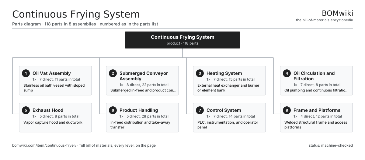
| # | Part | Qty | What it does |
|---|---|---|---|
| 1 | Oil Vat Assembly 7 parts | 1× | Stainless oil bath vessel with sloped sump |
| 2 | Submerged Conveyor Assembly 8 parts | 1× | Submerged in-feed and product conveyor system |
| 3 | Heating System 7 parts | 1× | External heat exchanger and burner or element bank |
| 4 | Oil Circulation and Filtration 7 parts | 1× | Oil pumping and continuous filtration loop |
| 5 | Exhaust Hood 5 parts | 1× | Vapor capture hood and ductwork |
| 6 | Product Handling 5 parts | 1× | In-feed distribution and take-away transfer |
| 7 | Control System 7 parts | 1× | PLC, instrumentation, and operator panel |
| 8 | Frame and Platforms 4 parts | 1× | Welded structural frame and access platforms |
3D model
No 3D model yet. Have a CAD file of this? Add a 3D model — STL renders right on this page; STEP, FreeCAD, and OpenSCAD sources are welcome too (openly licensed, like all 3D models on BOMwiki).
Build & assembly graph
expand / collapse · shared sub-assemblies converge · links to related products · est. labourTap an assembly to expand/collapse · tap a part to open it · use “Open page” for any node · drag to pan, scroll to zoom.
Bill of materials for Continuous Frying System
8 top-level lines · 62 rows shown · 118 parts total · indented to 3 levels| # | Item / sub-assembly | Part no. | Qty/assy | Ext. qty | Parts | Type |
|---|---|---|---|---|---|---|
| 1 | Oil Vat Assembly 7 parts | continuous-fryer-vat | 1× | 1 | 11 | assembly |
| 1.1 | Vat Tank | continuous-fryer-vat-tank | 1× | 1 | · | part |
| 1.2 | Sheet Metal Panel | sheet-panel | 4× | 4 | · | part |
| 1.3 | Vat Sump | continuous-fryer-vat-sump | 1× | 1 | · | part |
| 1.4 | Vat Insulation Jacket | continuous-fryer-vat-insulation | 1× | 1 | · | part |
| 1.5 | Vat Drain Valve | continuous-fryer-vat-drain-valve | 1× | 1 | · | part |
| 1.6 | Overflow Weir | continuous-fryer-vat-overflow-weir | 1× | 1 | · | part |
| 1.7 | Vat Cover | continuous-fryer-vat-cover | 2× | 2 | · | part |
| 2 | Submerged Conveyor Assembly 8 parts | continuous-fryer-conveyor | 1× | 1 | 22 | assembly |
| 2.1 | Conveyor Belt | continuous-fryer-conveyor-belt | 1× | 1 | · | part |
| 2.2 | Submerger Belt | continuous-fryer-conveyor-submerger-belt | 1× | 1 | · | part |
| 2.3 | Conveyor Drive Motor | continuous-fryer-conveyor-drive-motor | 1× | 1 | · | part |
| 2.4 | Conveyor Gearbox | continuous-fryer-conveyor-gearbox | 1× | 1 | · | part |
| 2.5 | Conveyor Sprocket | continuous-fryer-conveyor-sprocket | 4× | 4 | · | part |
| 2.6 | Conveyor Shaft | continuous-fryer-conveyor-shaft | 4× | 4 | · | part |
| 2.7 | Ball Bearing | ball-bearing | 8× | 8 | · | part |
| 2.8 | Belt Take-Up | continuous-fryer-conveyor-takeup | 2× | 2 | · | part |
| 3 | Heating System 7 parts | continuous-fryer-heating-system | 1× | 1 | 15 | assembly |
| 3.1 | Oil Heat Exchanger | continuous-fryer-heat-exchanger | 1× | 1 | · | part |
| 3.2 | Gas Burner | continuous-fryer-burner | 1× | 1 | · | part |
| 3.3 | Heating Element | heating-element | 6× | 6 | · | part |
| 3.4 | Combustion Air Fan | continuous-fryer-combustion-fan | 1× | 1 | · | part |
| 3.5 | Flue Stack | continuous-fryer-flue | 1× | 1 | · | part |
| 3.6 | Gas Train | continuous-fryer-gas-train | 1× | 1 | · | part |
| 3.7 | Temperature Probe | continuous-fryer-temp-probe | 4× | 4 | · | part |
| 4 | Oil Circulation and Filtration 7 parts | continuous-fryer-oil-circulation | 1× | 1 | 8 | assembly |
| 4.1 | Hot Oil Pump | continuous-fryer-oil-pump | 1× | 1 | · | part |
| 4.2 | Oil Filter | continuous-fryer-oil-filter | 1× | 1 | · | part |
| 4.3 | Filter Pre-Screen | continuous-fryer-filter-screen | 1× | 1 | · | part |
| 4.4 | Oil Circulation Piping | continuous-fryer-oil-piping | 1× | 1 | · | part |
| 4.5 | Makeup Oil Tank | continuous-fryer-makeup-tank | 1× | 1 | · | part |
| 4.6 | Makeup Oil Pump | continuous-fryer-makeup-pump | 1× | 1 | · | part |
| 4.7 | Pressure Sensor | pressure-sensor | 2× | 2 | · | part |
| 5 | Exhaust Hood 5 parts | continuous-fryer-exhaust-hood | 1× | 1 | 8 | assembly |
| 5.1 | Hood Canopy | continuous-fryer-hood-canopy | 1× | 1 | · | part |
| 5.2 | Hood Baffle Filter | continuous-fryer-hood-baffle-filter | 4× | 4 | · | part |
| 5.3 | Exhaust Fan | continuous-fryer-exhaust-fan | 1× | 1 | · | part |
| 5.4 | Hood Damper | continuous-fryer-hood-damper | 1× | 1 | · | part |
| 5.5 | Condensate Trough | continuous-fryer-condensate-trough | 1× | 1 | · | part |
| 6 | Product Handling 5 parts | continuous-fryer-product-handling | 1× | 1 | 28 | assembly |
| 6.1 | In-Feed Shaker | continuous-fryer-infeed-shaker | 1× | 1 | · | part |
| 6.2 | Discharge Conveyor | continuous-fryer-discharge-conveyor | 1× | 1 | · | part |
| 6.3 | De-Oiling Shaker | continuous-fryer-deoiling-shaker | 1× | 1 | · | part |
| 6.4 | Distribution Flights | continuous-fryer-distribution-flights | 1× | 1 | · | part |
| 6.5 | Servo Motor 4 parts | servo-motor | 1× | 1 | 24 | assembly |
| 6.5.1 | Stator Assembly 3 parts + deeper › | stator-assembly | 1× | 1 | 3 | assembly |
| 6.5.2 | Rotor Assembly 4 parts + deeper › | rotor-assembly | 1× | 1 | 19 | assembly |
| 6.5.3 | Encoder | encoder | 1× | 1 | · | part |
| 6.5.4 | Motor Housing | motor-housing | 1× | 1 | · | part |
| 7 | Control System 7 parts | continuous-fryer-control-system | 1× | 1 | 14 | assembly |
| 7.1 | PLC | continuous-fryer-plc | 1× | 1 | · | part |
| 7.2 | Operator HMI | continuous-fryer-hmi | 1× | 1 | · | part |
| 7.3 | Variable-Frequency Drive | continuous-fryer-vfd | 2× | 2 | · | part |
| 7.4 | Burner Management Controller | continuous-fryer-burner-controller | 1× | 1 | · | part |
| 7.5 | Relay | relay | 6× | 6 | · | part |
| 7.6 | Temperature Probe | continuous-fryer-temp-probe | 2× | 2 | · | part |
| 7.7 | Wire Bundle | wire-bundle | 1× | 1 | · | part |
| 8 | Frame and Platforms 4 parts | continuous-fryer-frame | 1× | 1 | 12 | assembly |
| 8.1 | Base Frame | continuous-fryer-base-frame | 1× | 1 | · | part |
| 8.2 | Access Platform | continuous-fryer-access-platform | 2× | 2 | · | part |
| 8.3 | Handrail Set | continuous-fryer-handrail | 1× | 1 | · | part |
| 8.4 | Leveling Foot | continuous-fryer-leveling-foot | 8× | 8 | · | part |
Related products
same domain, ranked by shared parts Membrane Filtration Skid
482 parts · shares 15 with this page
Membrane Filtration Skid
482 parts · shares 15 with this page
Sourcing: possible vendors
Prices, MOQ, and lead times are algorithmic estimates, not quotes, and not claims about these companies. Company mappings are curated by keyword; est. price band $1k–$500k. How estimates work| Vendor | HQ | Specialty | MOQ | Lead time |
|---|---|---|---|---|
| gea.com ↗ | Düsseldorf, DE | Process technology | 20 units | 12–20 wks |
| buhlergroup.com ↗ | Uzwil, CH | Food & materials processing | 20 units | 12–20 wks |
| tetrapak.com ↗ | Pully, CH | Food packaging & processing | 20 units | 12–20 wks |
| jbtc.com ↗ | Chicago, US | Food processing equipment | 20 units | 12–20 wks |
| alfalaval.com ↗ | Lund, SE | Heat transfer & separation | 20 units | 12–20 wks |
950-word article