Industrial Meat Mincer
ProductOverview
An industrial meat mincer reduces large volumes of meat to a uniform grind by forcing it through a rotating worm, past spinning knives, and through perforated plates. It is the workhorse of any plant that makes ground beef, sausage, burgers, pet food, or emulsion bases, and it handles hundreds to thousands of kilograms per hour. The principle is the same as a hand grinder, but everything is scaled up: the worm is a heavy hardened screw, the motor delivers tens of kilowatts, and the wetted parts are stainless steel built for daily wash-down.
The machine is built from a Feed System that holds and feeds the meat, a Grinding Head that does the cutting, a Drive Train that supplies torque, a Bone Separator that pulls out bone and sinew, a Mixer Section that blends lean and fat, a Frame and Housing that carries it all, and a Control Panel that runs the cycle. A Lubrication System system keeps the gearbox cool through long runs.
How it works
Meat is loaded into the Loading Hopper, where Hopper Paddle arms keep the cold load moving downward. The Feed Screw drags it through the Feed Throat and into the grinding worm. From there the worm compresses the meat against the knives and plates, building pressure as the flight pitch tightens. The grind size is set by the final plate: a coarse plate makes chili grind, a medium plate makes burger and sausage grind, and a fine plate makes an emulsion-ready paste. An operator changes plates and knives in minutes, which is why one machine can serve many products.
Grinding head
The Grinding Head is where the meat is actually cut. At its center is the Grinding Worm, a screw with a Worm Flight that tightens in pitch toward the outlet, a splined Worm Drive End that takes torque, and a Worm Tip that turns the first knife. Meat first meets the Kidney Plate, which pre-cuts it into manageable strands. It is then sheared between the rotating Knife Set and the stationary Plate Set. A two-stage head uses a Coarse Knife and coarse plate followed by a Fine Knife and fine plate, so the meat is reduced in two cuts for a cleaner grind and less smearing. The End Ring threads onto the Head Casting and clamps the stack, setting the contact pressure between each knife and plate. A worn Worm Liner in the bore is replaced rather than the whole casting.
Drive train
Grinding dense cold meat takes a lot of torque, so the Drive Train is sized generously. A three-phase Drive Motor, built around a Stator Assembly and a Rotor Assembly, drives the Gearbox through a flexible Drive Coupling. The coupling matters because a piece of bone reaching the worm produces a sudden shock, and the coupling absorbs that spike before it reaches the gear teeth. The gearbox uses two Helical Gear Pair stages inside a Gearbox Housing to trade motor speed for the slow, strong rotation the worm needs, and its Output Shaft couples directly to the worm. Heavy Ball Bearing sets carry the thrust the worm generates as it packs meat against the plate.
Materials and hygiene
Everything the meat touches is stainless steel, usually grade 304 or 316, because the machine is washed down with hot water and sanitizer after every shift. The Frame and Housing uses a welded Base Frame with smooth Sheet Metal Panel cladding, a sloped Drip Tray to route wash water to a drain, and Leveling Foot supports that let fluid drain underneath. The head strips down without tools so every surface can be cleaned and inspected. The Lubrication System system runs food-grade oil so any trace contact with product is safe.
Variants
Smaller bench units handle a few hundred kilograms an hour for butcher shops, while plant machines run continuously above two tonnes an hour. A grinder fitted with a Bone Separator becomes a deboner: its Separation Plate passes soft meat to the grind and sends hard bone out the Bone Chute, while a Sinew Screw pulls connective tissue clear. Machines with a Mixer Section blend lean and fat to a target ratio before grinding, which matters for sausage and burger work.
Use and maintenance
The wear parts are the knives and plates. Knife and plate faces must stay in flat contact, so they are reground or replaced when grinding turns to smearing or the output warms up. The Control Panel watches motor load and head pressure through its VFD and trips on a jam before the worm or gearbox is damaged, and the Emergency Stop cuts power at once. Daily care means checking oil at the Sight Glass, confirming the End Ring is torqued correctly, and full wash-down of the strip-down parts.
Industrial Meat Mincer parts and their functions
8 top-level parts · 114 parts in total · full bill of materials below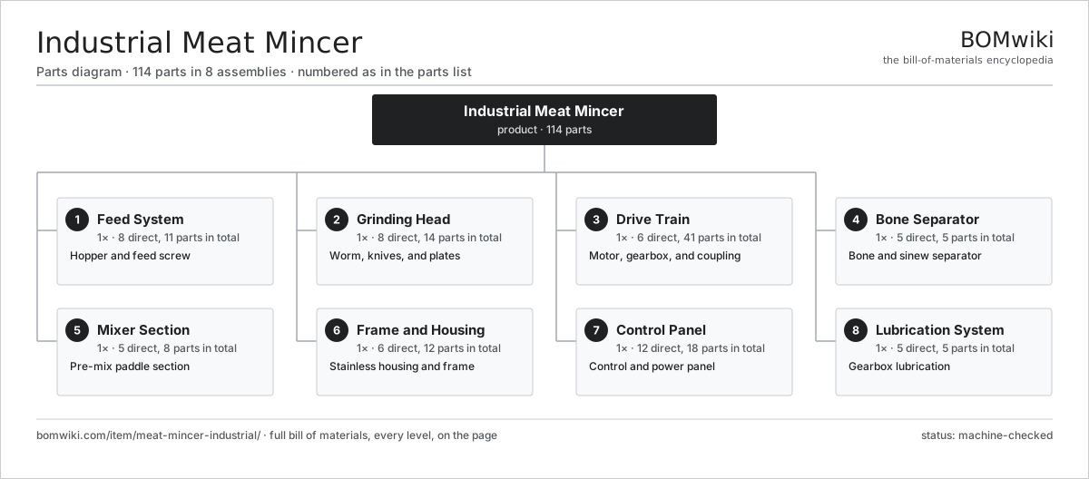
| # | Part | Qty | What it does |
|---|---|---|---|
| 1 | Feed System 8 parts | 1× | Hopper and feed screw |
| 2 | Grinding Head 8 parts | 1× | Worm, knives, and plates |
| 3 | Drive Train 6 parts | 1× | Motor, gearbox, and coupling |
| 4 | Bone Separator 5 parts | 1× | Bone and sinew separator |
| 5 | Mixer Section 5 parts | 1× | Pre-mix paddle section |
| 6 | Frame and Housing 6 parts | 1× | Stainless housing and frame |
| 7 | Control Panel 12 parts | 1× | Control and power panel |
| 8 | Lubrication System 5 parts | 1× | Gearbox lubrication |
3D model
No 3D model yet. Have a CAD file of this? Add a 3D model — STL renders right on this page; STEP, FreeCAD, and OpenSCAD sources are welcome too (openly licensed, like all 3D models on BOMwiki).
Build & assembly graph
expand / collapse · shared sub-assemblies converge · links to related products · est. labourTap an assembly to expand/collapse · tap a part to open it · use “Open page” for any node · drag to pan, scroll to zoom.
Bill of materials for Industrial Meat Mincer
8 top-level lines · 80 rows shown · 114 parts total · indented to 3 levels| # | Item / sub-assembly | Part no. | Qty/assy | Ext. qty | Parts | Type |
|---|---|---|---|---|---|---|
| 1 | Feed System 8 parts | meat-mincer-industrial-feed-system | 1× | 1 | 11 | assembly |
| 1.1 | Loading Hopper | meat-mincer-industrial-hopper | 1× | 1 | · | part |
| 1.2 | Feed Screw | meat-mincer-industrial-feed-screw | 1× | 1 | · | part |
| 1.3 | Feed Throat | meat-mincer-industrial-feed-throat | 1× | 1 | · | part |
| 1.4 | Feed Pan | meat-mincer-industrial-feed-pan | 1× | 1 | · | part |
| 1.5 | Hopper Paddle | meat-mincer-industrial-feed-paddle | 2× | 2 | · | part |
| 1.6 | Feed Bearing | meat-mincer-industrial-feed-bearing | 2× | 2 | · | part |
| 1.7 | Oil Seal | oil-seal | 2× | 2 | · | part |
| 1.8 | Fastener Set | fastener-set | 1× | 1 | · | part |
| 2 | Grinding Head 8 parts | meat-mincer-industrial-grinding-head | 1× | 1 | 14 | assembly |
| 2.1 | Head Casting | meat-mincer-industrial-head-casting | 1× | 1 | · | part |
| 2.2 | Grinding Worm 3 parts | meat-mincer-industrial-worm | 1× | 1 | 3 | assembly |
| 2.2.1 | Worm Flight | meat-mincer-industrial-worm-flight | 1× | 1 | · | part |
| 2.2.2 | Worm Drive End | meat-mincer-industrial-worm-drive-end | 1× | 1 | · | part |
| 2.2.3 | Worm Tip | meat-mincer-industrial-worm-tip | 1× | 1 | · | part |
| 2.3 | Knife Set 3 parts | meat-mincer-industrial-knife-set | 1× | 1 | 3 | assembly |
| 2.3.1 | Coarse Knife | meat-mincer-industrial-coarse-knife | 1× | 1 | · | part |
| 2.3.2 | Fine Knife | meat-mincer-industrial-fine-knife | 1× | 1 | · | part |
| 2.3.3 | Knife Hub | meat-mincer-industrial-knife-hub | 1× | 1 | · | part |
| 2.4 | Plate Set 3 parts | meat-mincer-industrial-plate-set | 1× | 1 | 3 | assembly |
| 2.4.1 | Coarse Plate | meat-mincer-industrial-coarse-plate | 1× | 1 | · | part |
| 2.4.2 | Medium Plate | meat-mincer-industrial-medium-plate | 1× | 1 | · | part |
| 2.4.3 | Fine Plate | meat-mincer-industrial-fine-plate | 1× | 1 | · | part |
| 2.5 | Kidney Plate | meat-mincer-industrial-kidney-plate | 1× | 1 | · | part |
| 2.6 | End Ring | meat-mincer-industrial-end-ring | 1× | 1 | · | part |
| 2.7 | Knife Shaft | meat-mincer-industrial-knife-shaft | 1× | 1 | · | part |
| 2.8 | Worm Liner | meat-mincer-industrial-worm-liner | 1× | 1 | · | part |
| 3 | Drive Train 6 parts | meat-mincer-industrial-drive-train | 1× | 1 | 41 | assembly |
| 3.1 | Drive Motor 4 parts | meat-mincer-industrial-motor | 1× | 1 | 25 | assembly |
| 3.1.1 | Stator Assembly 3 parts + deeper › | stator-assembly | 1× | 1 | 3 | assembly |
| 3.1.2 | Rotor Assembly 4 parts + deeper › | rotor-assembly | 1× | 1 | 19 | assembly |
| 3.1.3 | Motor Fan | meat-mincer-industrial-motor-fan | 1× | 1 | · | part |
| 3.1.4 | Ball Bearing | ball-bearing | 2× | 2 | · | part |
| 3.2 | Gearbox 4 parts | meat-mincer-industrial-gearbox | 1× | 1 | 9 | assembly |
| 3.2.1 | Gearbox Housing | gearbox-housing | 1× | 1 | · | part |
| 3.2.2 | Helical Gear Pair | gear-pair | 2× | 2 | · | part |
| 3.2.3 | Ball Bearing | ball-bearing | 4× | 4 | · | part |
| 3.2.4 | Oil Seal | oil-seal | 2× | 2 | · | part |
| 3.3 | Drive Coupling | meat-mincer-industrial-coupling | 1× | 1 | · | part |
| 3.4 | Output Shaft | meat-mincer-industrial-output-shaft | 1× | 1 | · | part |
| 3.5 | Ball Bearing | ball-bearing | 4× | 4 | · | part |
| 3.6 | O-Ring Set | oring-set | 1× | 1 | · | part |
| 4 | Bone Separator 5 parts | meat-mincer-industrial-separator | 1× | 1 | 5 | assembly |
| 4.1 | Separation Plate | meat-mincer-industrial-separator-plate | 1× | 1 | · | part |
| 4.2 | Bone Chute | meat-mincer-industrial-bone-chute | 1× | 1 | · | part |
| 4.3 | Sinew Screw | meat-mincer-industrial-sinew-screw | 1× | 1 | · | part |
| 4.4 | Pressure Ring | meat-mincer-industrial-pressure-ring | 1× | 1 | · | part |
| 4.5 | Oil Seal | oil-seal | 1× | 1 | · | part |
| 5 | Mixer Section 5 parts | meat-mincer-industrial-mixer | 1× | 1 | 8 | assembly |
| 5.1 | Mixing Trough | meat-mincer-industrial-mix-trough | 1× | 1 | · | part |
| 5.2 | Mixing Paddle | meat-mincer-industrial-mix-paddle | 2× | 2 | · | part |
| 5.3 | Paddle Shaft | meat-mincer-industrial-mix-shaft | 1× | 1 | · | part |
| 5.4 | Ball Bearing | ball-bearing | 2× | 2 | · | part |
| 5.5 | Oil Seal | oil-seal | 2× | 2 | · | part |
| 6 | Frame and Housing 6 parts | meat-mincer-industrial-frame | 1× | 1 | 12 | assembly |
| 6.1 | Base Frame | meat-mincer-industrial-frame-weldment | 1× | 1 | · | part |
| 6.2 | Sheet Metal Panel | sheet-panel | 4× | 4 | · | part |
| 6.3 | Leveling Foot | meat-mincer-industrial-leveling-foot | 4× | 4 | · | part |
| 6.4 | Drip Tray | meat-mincer-industrial-drip-tray | 1× | 1 | · | part |
| 6.5 | Access Door | meat-mincer-industrial-access-door | 1× | 1 | · | part |
| 6.6 | Fastener Set | fastener-set | 1× | 1 | · | part |
| 7 | Control Panel 12 parts | meat-mincer-industrial-control-panel | 1× | 1 | 18 | assembly |
| 7.1 | Control Enclosure | meat-mincer-industrial-enclosure | 1× | 1 | · | part |
| 7.2 | VFD | meat-mincer-industrial-vfd | 1× | 1 | · | part |
| 7.3 | Controller | meat-mincer-industrial-controller | 1× | 1 | · | part |
| 7.4 | Microcontroller | mcu | 1× | 1 | · | part |
| 7.5 | Bare PCB | pcb-bare | 1× | 1 | · | part |
| 7.6 | SMD Passive (R/C/L) | smd-passives | 1× | 1 | · | part |
| 7.7 | Relay | relay | 2× | 2 | · | part |
| 7.8 | LCD Panel | lcd-panel | 1× | 1 | · | part |
| 7.9 | Emergency Stop | meat-mincer-industrial-estop | 1× | 1 | · | part |
| 7.10 | Pressure Sensor | pressure-sensor | 1× | 1 | · | part |
| 7.11 | Connector | connector | 6× | 6 | · | part |
| 7.12 | Wire Bundle | wire-bundle | 1× | 1 | · | part |
| 8 | Lubrication System 5 parts | meat-mincer-industrial-lubrication | 1× | 1 | 5 | assembly |
| 8.1 | Oil Reservoir | meat-mincer-industrial-oil-reservoir | 1× | 1 | · | part |
| 8.2 | Oil Pump | meat-mincer-industrial-oil-pump | 1× | 1 | · | part |
| 8.3 | Oil Filter | meat-mincer-industrial-oil-filter | 1× | 1 | · | part |
| 8.4 | Sight Glass | meat-mincer-industrial-sight-glass | 1× | 1 | · | part |
| 8.5 | O-Ring Set | oring-set | 1× | 1 | · | part |
Related products
same domain, ranked by shared parts Edible Oil Refining Line
3,224 parts · shares 20 with this page
Egg Breaking and Separating Line
1,126 parts · shares 20 with this page
Edible Oil Refining Line
3,224 parts · shares 20 with this page
Egg Breaking and Separating Line
1,126 parts · shares 20 with this page
 Hydrostatic Sterilizer
9,247 parts · shares 20 with this page
Industrial Bowl Cutter
280 parts · shares 20 with this page
Hydrostatic Sterilizer
9,247 parts · shares 20 with this page
Industrial Bowl Cutter
280 parts · shares 20 with this page
 Industrial Coffee Grinder
788 parts · shares 20 with this page
Industrial Coffee Grinder
788 parts · shares 20 with this page
Sourcing: possible vendors
Prices, MOQ, and lead times are algorithmic estimates, not quotes, and not claims about these companies. Company mappings are curated by keyword; est. price band $1k–$500k. How estimates work| Vendor | HQ | Specialty | MOQ | Lead time |
|---|---|---|---|---|
| gea.com ↗ | Düsseldorf, DE | Process technology | 20 units | 12–20 wks |
| buhlergroup.com ↗ | Uzwil, CH | Food & materials processing | 20 units | 12–20 wks |
| tetrapak.com ↗ | Pully, CH | Food packaging & processing | 20 units | 12–20 wks |
| jbtc.com ↗ | Chicago, US | Food processing equipment | 20 units | 12–20 wks |
| alfalaval.com ↗ | Lund, SE | Heat transfer & separation | 20 units | 12–20 wks |
916-word article