Food Decanter Centrifuge
ProductOverview
A decanter centrifuge separates solids from a liquid continuously by spinning the mixture fast inside a horizontal bowl while a slightly slower internal screw scrapes the settled solids out one end. It runs without stopping, taking a slurry in at one point and discharging clarified liquid and dewatered cake at the same time. In food plants it presses olive oil from paste, recovers juice and clarifies it, dewaters starch and gluten, and concentrates fish and meat by-products.
Unlike a filter, the decanter uses no cloth or screen to do the primary separation. Centrifugal force does the work, throwing dense solids against the Bowl Shell while lighter liquid stays nearer the axis. This makes it well suited to slimy, fine, or fibrous solids that would blind a filter.
How it works
Slurry enters through the stationary Stationary Feed Pipe and arrives at the Feed Acceleration Zone in the center of the Scroll Conveyor. The feed zone accelerates the incoming material up to bowl speed and ejects it into the separation pool. Spinning at several thousand rpm, the Bowl Assembly generates a few thousand times gravity, so solids settle out against the inner wall of the Bowl Shell in seconds.
The Scroll Conveyor, a helical screw that fills the bowl, turns at a slightly different speed than the bowl. That small difference, the differential speed, is what conveys the settled solids. The Helical Flight flight ploughs the solids along the cylindrical section and up the Conical Beach Section beach, which rises out of the liquid pool. As the cake climbs the dry beach it drains, then drops out through the Solids Discharge Port. Clarified liquid, called centrate, flows the other way and overflows the adjustable Adjustable Weir Plate at the cylindrical end.
Bowl and scroll
The Bowl Shell is forged from duplex stainless steel because it must hold several thousand g without yielding. The Adjustable Weir Plate plates set the pool depth: a deeper pool gives clearer centrate but a wetter cake, a shallower pool the reverse, so operators tune them for the product. The Conical Beach Section beach angle controls how much the cake dewaters before it leaves.
The Scroll Conveyor takes the most wear because it is constantly dragging abrasive solids. The leading edge of the Helical Flight is faced with Flight Edge Wear Tile tungsten carbide tiles, and the Solids Discharge Port openings are lined with a Tungsten Carbide Wear Tile to survive the high-velocity solids stream. The Feed Acceleration Zone is similarly hardened.
Differential drive
The differential speed between bowl and scroll is set by the Differential Gearbox, a planetary or cycloidal unit whose Planet Carrier couples the two rotating members. On a modern machine the Backdrive Shaft of the gearbox is driven by a separate Backdrive Motor so the differential speed can be varied while running. This lets the control system hold scroll torque, measured by the Scroll Torque Sensor, constant even as the solids load changes, which keeps the cake dryness steady.
Main drive and frame
The Main Drive spins the whole rotating assembly. A belt-driven Main Drive Motor turns the bowl through Drive Belt V-belts and pulleys, and a Disc Brake brings the heavy bowl to a controlled stop. The entire rotor sits on the Frame & Casing, which rests on Vibration Isolation Mount isolators because any rotor imbalance at thousands of rpm would shake the building otherwise. The Collector Hood separates the Liquid (Centrate) Chute from the Solids Discharge Chute so the two streams never mix.
Lubrication and bearings
The bowl and scroll ride on heavy-duty Ball Bearing bearings that see continuous high speed and load. The Lubrication System circulates oil through them and through the Differential Gearbox, with an Oil Cooler to carry away frictional heat and an Oil Filter to keep wear particles out. Bearing condition is the single biggest factor in decanter reliability, so it is monitored continuously.
Control and monitoring
The Control System runs the machine and protects it. Vibration Sensor units watch for imbalance from uneven feed or bearing wear and will trip the machine before damage occurs. Two Variable Frequency Drive drives, one for the main motor and one for the backdrive, let the operator set bowl speed and differential independently from the Operator HMI Panel. The Feed Pump is interlocked so feed only starts once the bowl is at full speed.
Variants and use
Decanters are tuned to the product. A two-phase machine splits solids from one liquid, as in starch dewatering. A three-phase machine adds a second liquid outlet to split oil, water, and solids in a single pass, the standard for olive oil extraction. Longer bowls with a higher length-to-diameter ratio give clearer centrate for juice clarification, while shorter bowls maximize solids throughput for dewatering duties. The core principle, settle under high g and convey with a differential screw, holds across all of them.
Food Decanter Centrifuge parts and their functions
8 top-level parts · 509 parts in total · full bill of materials below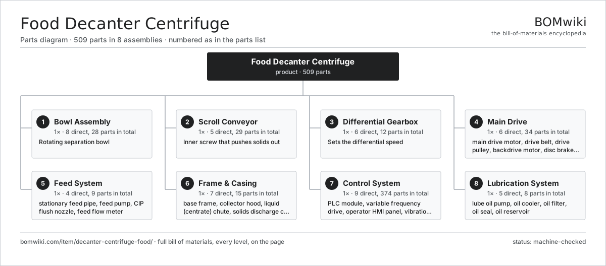
| # | Part | Qty | What it does |
|---|---|---|---|
| 1 | Bowl Assembly 8 parts | 1× | Rotating separation bowl |
| 2 | Scroll Conveyor 5 parts | 1× | Inner screw that pushes solids out |
| 3 | Differential Gearbox 6 parts | 1× | Sets the differential speed |
| 4 | Main Drive 6 parts | 1× | Belt-driven main motor plus backdrive motor and brake. |
| 5 | Feed System 4 parts | 1× | Pipe and pump that deliver slurry into the rotating feed zone. |
| 6 | Frame & Casing 7 parts | 1× | Vibration-isolated base and the splash-tight collector hood. |
| 7 | Control System 9 parts | 1× | PLC, VFDs and vibration monitoring. |
| 8 | Lubrication System 5 parts | 1× | Oil bath and circulation for the bearings and gearbox. |
3D model
No 3D model yet. Have a CAD file of this? Add a 3D model — STL renders right on this page; STEP, FreeCAD, and OpenSCAD sources are welcome too (openly licensed, like all 3D models on BOMwiki).
Build & assembly graph
expand / collapse · shared sub-assemblies converge · links to related products · est. labourTap an assembly to expand/collapse · tap a part to open it · use “Open page” for any node · drag to pan, scroll to zoom.
Bill of materials for Food Decanter Centrifuge
8 top-level lines · 79 rows shown · 509 parts total · indented to 3 levels| # | Item / sub-assembly | Part no. | Qty/assy | Ext. qty | Parts | Type |
|---|---|---|---|---|---|---|
| 1 | Bowl Assembly 8 parts | dcf-bowl-assembly | 1× | 1 | 28 | assembly |
| 1.1 | Bowl Shell | dcf-bowl-shell | 1× | 1 | · | part |
| 1.2 | Conical Beach Section | dcf-conical-end | 1× | 1 | · | part |
| 1.3 | Cylindrical Section | dcf-cylindrical-section | 1× | 1 | · | part |
| 1.4 | Solids Discharge Port 2 parts | dcf-solids-discharge-port | 8× | 8 | 2 | assembly |
| 1.4.1 | Discharge Bushing | dcf-discharge-bushing | 1× | 8 | · | part |
| 1.4.2 | Tungsten Carbide Wear Tile | dcf-tungsten-tile | 1× | 8 | · | part |
| 1.5 | Adjustable Weir Plate | dcf-weir-plate | 4× | 4 | · | part |
| 1.6 | Bowl Hub | dcf-bowl-hub | 2× | 2 | · | part |
| 1.7 | Ball Bearing | ball-bearing | 2× | 2 | · | part |
| 1.8 | Fastener Set | fastener-set | 1× | 1 | · | part |
| 2 | Scroll Conveyor 5 parts | dcf-scroll-conveyor | 1× | 1 | 29 | assembly |
| 2.1 | Scroll Body | dcf-scroll-body | 1× | 1 | · | part |
| 2.2 | Helical Flight | dcf-scroll-flight | 1× | 1 | · | part |
| 2.3 | Flight Edge Wear Tile | dcf-flight-tile | 24× | 24 | · | part |
| 2.4 | Feed Acceleration Zone | dcf-feed-zone | 1× | 1 | · | part |
| 2.5 | Ball Bearing | ball-bearing | 2× | 2 | · | part |
| 3 | Differential Gearbox 6 parts | dcf-gearbox | 1× | 1 | 12 | assembly |
| 3.1 | Gearbox Housing | gearbox-housing | 1× | 1 | · | part |
| 3.2 | Helical Gear Pair | gear-pair | 3× | 3 | · | part |
| 3.3 | Planet Carrier | dcf-planet-carrier | 1× | 1 | · | part |
| 3.4 | Ball Bearing | ball-bearing | 4× | 4 | · | part |
| 3.5 | Oil Seal | oil-seal | 2× | 2 | · | part |
| 3.6 | Backdrive Shaft | dcf-backdrive-shaft | 1× | 1 | · | part |
| 4 | Main Drive 6 parts | dcf-main-drive | 1× | 1 | 34 | assembly |
| 4.1 | Main Drive Motor 4 parts | dcf-main-motor | 1× | 1 | 25 | assembly |
| 4.1.1 | Stator Assembly 3 parts + deeper › | stator-assembly | 1× | 1 | 3 | assembly |
| 4.1.2 | Rotor Assembly 4 parts + deeper › | rotor-assembly | 1× | 1 | 19 | assembly |
| 4.1.3 | Ball Bearing | ball-bearing | 2× | 2 | · | part |
| 4.1.4 | Oil Seal | oil-seal | 1× | 1 | · | part |
| 4.2 | Drive Belt | drive-belt | 4× | 4 | · | part |
| 4.3 | Drive Pulley | dcf-belt-pulley | 2× | 2 | · | part |
| 4.4 | Backdrive Motor | dcf-backdrive-motor | 1× | 1 | · | part |
| 4.5 | Disc Brake | dcf-brake | 1× | 1 | · | part |
| 4.6 | Belt Guard | dcf-belt-guard | 1× | 1 | · | part |
| 5 | Feed System 4 parts | dcf-feed-system | 1× | 1 | 9 | assembly |
| 5.1 | Stationary Feed Pipe | dcf-feed-pipe | 1× | 1 | · | part |
| 5.2 | Feed Pump 4 parts | dcf-feed-pump | 1× | 1 | 5 | assembly |
| 5.2.1 | Feed Pump Casing | dcf-feed-pump-casing | 1× | 1 | · | part |
| 5.2.2 | Feed Impeller | dcf-feed-impeller | 1× | 1 | · | part |
| 5.2.3 | Ball Bearing | ball-bearing | 2× | 2 | · | part |
| 5.2.4 | Oil Seal | oil-seal | 1× | 1 | · | part |
| 5.3 | CIP Flush Nozzle | dcf-flush-nozzle | 2× | 2 | · | part |
| 5.4 | Feed Flow Meter | dcf-flow-meter | 1× | 1 | · | part |
| 6 | Frame & Casing 7 parts | dcf-frame-casing | 1× | 1 | 15 | assembly |
| 6.1 | Base Frame | dcf-base-frame | 1× | 1 | · | part |
| 6.2 | Collector Hood | dcf-collector-hood | 1× | 1 | · | part |
| 6.3 | Liquid (Centrate) Chute | dcf-liquid-chute | 1× | 1 | · | part |
| 6.4 | Solids Discharge Chute | dcf-solids-chute | 1× | 1 | · | part |
| 6.5 | Vibration Isolation Mount | dcf-vibration-mount | 4× | 4 | · | part |
| 6.6 | Sheet Metal Panel | sheet-panel | 6× | 6 | · | part |
| 6.7 | Fastener Set | fastener-set | 1× | 1 | · | part |
| 7 | Control System 9 parts | dcf-control-system | 1× | 1 | 374 | assembly |
| 7.1 | PLC Module 4 parts | dcf-plc | 1× | 1 | 124 | assembly |
| 7.1.1 | Bare PCB | pcb-bare | 1× | 1 | · | part |
| 7.1.2 | Microcontroller | mcu | 1× | 1 | · | part |
| 7.1.3 | SMD Passive (R/C/L) | smd-passives | 120× | 120 | · | part |
| 7.1.4 | I/O Card | dcf-io-card | 2× | 2 | · | part |
| 7.2 | Variable Frequency Drive 4 parts | dcf-vfd | 2× | 2 | 108 | assembly |
| 7.2.1 | Bare PCB | pcb-bare | 1× | 2 | · | part |
| 7.2.2 | Microcontroller | mcu | 1× | 2 | · | part |
| 7.2.3 | IGBT Power Module | dcf-igbt-module | 6× | 12 | · | part |
| 7.2.4 | SMD Passive (R/C/L) | smd-passives | 100× | 200 | · | part |
| 7.3 | Operator HMI Panel 3 parts | dcf-hmi | 1× | 1 | 3 | assembly |
| 7.3.1 | LCD Panel | lcd-panel | 1× | 1 | · | part |
| 7.3.2 | Touch Glass | dcf-touch-glass | 1× | 1 | · | part |
| 7.3.3 | Bare PCB | pcb-bare | 1× | 1 | · | part |
| 7.4 | Vibration Sensor | dcf-vibration-sensor | 2× | 2 | · | part |
| 7.5 | Scroll Torque Sensor | dcf-torque-sensor | 1× | 1 | · | part |
| 7.6 | Power Supply | power-supply | 1× | 1 | · | part |
| 7.7 | Relay | relay | 6× | 6 | · | part |
| 7.8 | Wire Bundle | wire-bundle | 1× | 1 | · | part |
| 7.9 | Connector | connector | 20× | 20 | · | part |
| 8 | Lubrication System 5 parts | dcf-lube-system | 1× | 1 | 8 | assembly |
| 8.1 | Lube Oil Pump | dcf-oil-pump | 1× | 1 | · | part |
| 8.2 | Oil Cooler | dcf-oil-cooler | 1× | 1 | · | part |
| 8.3 | Oil Filter | dcf-oil-filter | 1× | 1 | · | part |
| 8.4 | Oil Seal | oil-seal | 4× | 4 | · | part |
| 8.5 | Oil Reservoir | dcf-oil-reservoir | 1× | 1 | · | part |
Related products
same domain, ranked by shared parts Can Seaming Machine
658 parts · shares 20 with this page
Dough Sheeting Line
456 parts · shares 20 with this page
Can Seaming Machine
658 parts · shares 20 with this page
Dough Sheeting Line
456 parts · shares 20 with this page
 Edible Oil Refining Line
3,224 parts · shares 20 with this page
Egg Breaking and Separating Line
1,126 parts · shares 20 with this page
Edible Oil Refining Line
3,224 parts · shares 20 with this page
Egg Breaking and Separating Line
1,126 parts · shares 20 with this page
 Flour Milling Plant
2,774 parts · shares 20 with this page
Flour Milling Plant
2,774 parts · shares 20 with this page
Sourcing: possible vendors
Prices, MOQ, and lead times are algorithmic estimates, not quotes, and not claims about these companies. Company mappings are curated by keyword; est. price band $1k–$500k. How estimates work| Vendor | HQ | Specialty | MOQ | Lead time |
|---|---|---|---|---|
| gea.com ↗ | Düsseldorf, DE | Process technology | 20 units | 12–20 wks |
| buhlergroup.com ↗ | Uzwil, CH | Food & materials processing | 20 units | 12–20 wks |
| tetrapak.com ↗ | Pully, CH | Food packaging & processing | 20 units | 12–20 wks |
| jbtc.com ↗ | Chicago, US | Food processing equipment | 20 units | 12–20 wks |
| alfalaval.com ↗ | Lund, SE | Heat transfer & separation | 20 units | 12–20 wks |
837-word article