Forced-Circulation Evaporator
ProductOverview
A forced-circulation evaporator concentrates liquid foods by boiling off water under vacuum while a pump keeps the product moving fast through the heating tubes. The forced flow is the defining feature. In a natural-circulation or falling-film unit the product moves on its own, but viscous, fouling, or crystallizing liquids do not move fast enough that way and they scorch on the tube wall. The Forced-Circulation Pump solves this by pushing product through the Calandria (Tube Bundle) at 2 to 4 m/s, far faster than gravity alone would carry it.
Because the product flow is forced, this evaporator handles materials that defeat other designs: tomato paste at 30 percent solids, glucose and sugar syrups that crystallize, fruit purees with pulp, and gelatin or starch slurries. It is the workhorse of high-concentration food and process duty.
The unit runs under vacuum so the product boils at 40 to 70 deg C rather than 100 deg C. Lower boiling temperature protects flavor, color, and heat-sensitive vitamins, and it lets low-pressure steam do the heating.
How it works
Feed enters the Product Piping and joins the recirculating stream. The Forced-Circulation Pump drives this combined stream up through the Product Tube Bundle inside the Calandria (Tube Bundle). Steam condenses on the outside of the Heat-Transfer Tube tubes and transfers its latent heat into the product.
Here is the key trick: the product inside the tubes is kept under enough static pressure that it does not boil while it is in the heating zone. It only superheats. The hot, pressurized stream then shoots into the Separator Vessel, where the pressure suddenly drops to the vessel vacuum. The superheated liquid flashes, meaning a fraction of it boils instantly into vapor.
The Tangential Inlet Elbow spins the incoming flow so liquid is thrown to the wall and vapor rises up the center. A Demister Pad near the top catches entrained droplets so they do not carry over into the vapor line. Concentrated liquid collects in the bottom of the vessel, where most of it is drawn back into the circulation loop for another pass, and a controlled bleed of finished concentrate is withdrawn.
Vapor and vacuum system
The vapor leaving the separator still carries large latent heat. The Vapor & Vacuum System recovers and disposes of it. A Thermocompressor, which is a steam-driven jet ejector, recompresses part of the vapor and feeds it back to the steam side of the Calandria (Tube Bundle), cutting fresh steam use. The rest of the vapor goes to the Surface Condenser.
The vacuum itself is held by a Liquid-Ring Vacuum Pump of the liquid-ring type. Its Liquid-Ring Rotor spins eccentrically inside a partly water-filled Vacuum Pump Body, forming moving liquid pockets that pull non-condensable gases out of the system. Vacuum level sets the boiling temperature directly, so the control system trims the vacuum pump to hold the target.
Condenser and condensate
The Surface Condenser is a surface or direct-contact unit that turns spent vapor back into water using cooling water through the Condenser Tube Bundle. The recovered condensate, together with the steam condensate from the heating side, is pumped away by the Condensate Pump and a Steam Trap. In a multiple-effect arrangement, the vapor from one effect becomes the heating steam for the next, which is what raises steam economy from roughly 0.9 up toward 6 kg of water removed per kg of fresh steam.
Materials and hygiene
Every product-contact surface is stainless steel 304 or 316L with a polished, crevice-free finish so the unit can be cleaned in place. The Heat-Transfer Tube tubes are expanded into the Tube Sheet plates with a hygienic joint that leaves no pockets for product to lodge. The Mechanical Seal on the circulation pump is a double seal with a clean flush so the bearing oil never reaches the product.
The Clean-in-Place System runs automated caustic and acid wash cycles through Rotary Spray Ball heads and the full recirculation loop. Because the product side fouls, especially with milk proteins and sugars, regular CIP keeps the Product Tube Bundle heat transfer from degrading between production runs.
Instrumentation and control
The Control System coordinates the whole process. An Inline Density Meter of the Coriolis type measures concentration in real time and trims the concentrate bleed valve to hold the target total solids. A Level Probe keeps the separator pool steady, Pressure Sensor units watch the vacuum, and RTD Temperature Sensor RTDs track boiling temperature so the steam valve can hold it within a degree. The operator runs everything from the Operator HMI Panel, driven by the PLC Module.
Variants and use
Single-effect units suit small or batch food plants. Two to five effects in series are standard for large continuous duty such as tomato paste and dairy, trading capital cost for steam economy. Mechanical vapor recompression replaces the Thermocompressor and condenser with an electric vapor blower where electricity is cheaper than steam. A finishing effect with extra residence time is added when the product crystallizes, as in sugar and glucose lines. Whatever the configuration, the Forced-Circulation Pump and the flash-in-the-separator principle stay the same, which is what lets this machine push food up to 70 percent solids without burning it.
Forced-Circulation Evaporator parts and their functions
9 top-level parts · 414 parts in total · full bill of materials below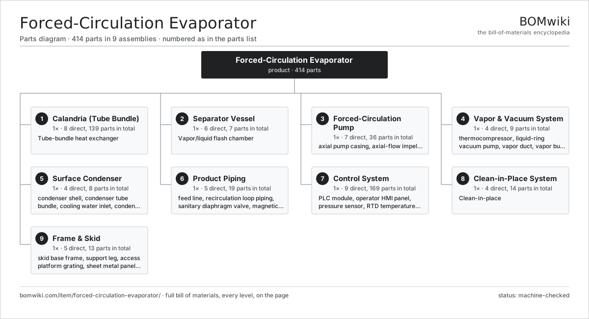
| # | Part | Qty | What it does |
|---|---|---|---|
| 1 | Calandria (Tube Bundle) 8 parts | 1× | Tube-bundle heat exchanger |
| 2 | Separator Vessel 6 parts | 1× | Vapor/liquid flash chamber |
| 3 | Forced-Circulation Pump 7 parts | 1× | High-flow axial pump that drives product through the tubes faster than it would boil. |
| 4 | Vapor & Vacuum System 4 parts | 1× | Generates and holds the boiling vacuum. |
| 5 | Surface Condenser 4 parts | 1× | Condenses spent vapor with cooling water. |
| 6 | Product Piping 5 parts | 1× | Sanitary feed, recirculation and product-out lines. |
| 7 | Control System 9 parts | 1× | PLC, instrumentation and operator interface. |
| 8 | Clean-in-Place System 4 parts | 1× | Clean-in-place |
| 9 | Frame & Skid 5 parts | 1× | Structural support and platform. |
3D model
No 3D model yet. Have a CAD file of this? Add a 3D model — STL renders right on this page; STEP, FreeCAD, and OpenSCAD sources are welcome too (openly licensed, like all 3D models on BOMwiki).
Build & assembly graph
expand / collapse · shared sub-assemblies converge · links to related products · est. labourTap an assembly to expand/collapse · tap a part to open it · use “Open page” for any node · drag to pan, scroll to zoom.
Bill of materials for Forced-Circulation Evaporator
9 top-level lines · 89 rows shown · 414 parts total · indented to 3 levels| # | Item / sub-assembly | Part no. | Qty/assy | Ext. qty | Parts | Type |
|---|---|---|---|---|---|---|
| 1 | Calandria (Tube Bundle) 8 parts | fce-calandria | 1× | 1 | 139 | assembly |
| 1.1 | Heater Shell | fce-shell | 1× | 1 | · | part |
| 1.2 | Product Tube Bundle 2 parts | fce-tube-bundle | 1× | 1 | 128 | assembly |
| 1.2.1 | Heat-Transfer Tube | fce-heat-tube | 120× | 120 | · | part |
| 1.2.2 | Tube Spacer Grid | fce-tube-spacer | 8× | 8 | · | part |
| 1.3 | Tube Sheet | fce-tube-sheet | 2× | 2 | · | part |
| 1.4 | Steam Inlet Nozzle | fce-steam-inlet-nozzle | 1× | 1 | · | part |
| 1.5 | Steam Trap | fce-condensate-trap | 1× | 1 | · | part |
| 1.6 | Shell-Side Baffle Set | fce-baffle-set | 1× | 1 | · | part |
| 1.7 | O-Ring Set | oring-set | 4× | 4 | · | part |
| 1.8 | Fastener Set | fastener-set | 1× | 1 | · | part |
| 2 | Separator Vessel 6 parts | fce-separator-vessel | 1× | 1 | 7 | assembly |
| 2.1 | Flash Chamber Body | fce-flash-chamber | 1× | 1 | · | part |
| 2.2 | Tangential Inlet Elbow | fce-tangential-inlet | 1× | 1 | · | part |
| 2.3 | Demister Pad | fce-demister-pad | 1× | 1 | · | part |
| 2.4 | Sight Glass | fce-sight-glass | 2× | 2 | · | part |
| 2.5 | Level Probe | fce-level-probe | 1× | 1 | · | part |
| 2.6 | Vacuum Connection Nozzle | fce-vacuum-nozzle | 1× | 1 | · | part |
| 3 | Forced-Circulation Pump 7 parts | fce-circulation-pump | 1× | 1 | 36 | assembly |
| 3.1 | Axial Pump Casing | fce-pump-casing | 1× | 1 | · | part |
| 3.2 | Axial-Flow Impeller | fce-axial-impeller | 1× | 1 | · | part |
| 3.3 | Pump Shaft | fce-pump-shaft | 1× | 1 | · | part |
| 3.4 | Mechanical Seal 3 parts | fce-mechanical-seal | 1× | 1 | 5 | assembly |
| 3.4.1 | Seal Face (SiC) | fce-seal-face | 2× | 2 | · | part |
| 3.4.2 | Seal Spring | fce-seal-spring | 1× | 1 | · | part |
| 3.4.3 | O-Ring Set | oring-set | 2× | 2 | · | part |
| 3.5 | Servo Motor 4 parts | servo-motor | 1× | 1 | 24 | assembly |
| 3.5.1 | Stator Assembly 3 parts + deeper › | stator-assembly | 1× | 1 | 3 | assembly |
| 3.5.2 | Rotor Assembly 4 parts + deeper › | rotor-assembly | 1× | 1 | 19 | assembly |
| 3.5.3 | Encoder | encoder | 1× | 1 | · | part |
| 3.5.4 | Motor Housing | motor-housing | 1× | 1 | · | part |
| 3.6 | Ball Bearing | ball-bearing | 2× | 2 | · | part |
| 3.7 | Oil Seal | oil-seal | 2× | 2 | · | part |
| 4 | Vapor & Vacuum System 4 parts | fce-vapor-system | 1× | 1 | 9 | assembly |
| 4.1 | Thermocompressor | fce-thermocompressor | 1× | 1 | · | part |
| 4.2 | Liquid-Ring Vacuum Pump 4 parts | fce-vacuum-pump | 1× | 1 | 5 | assembly |
| 4.2.1 | Liquid-Ring Rotor | fce-vacuum-rotor | 1× | 1 | · | part |
| 4.2.2 | Vacuum Pump Body | fce-vacuum-body | 1× | 1 | · | part |
| 4.2.3 | Ball Bearing | ball-bearing | 2× | 2 | · | part |
| 4.2.4 | Oil Seal | oil-seal | 1× | 1 | · | part |
| 4.3 | Vapor Duct | fce-vapor-duct | 1× | 1 | · | part |
| 4.4 | Vapor Butterfly Valve | fce-vapor-valve | 2× | 2 | · | part |
| 5 | Surface Condenser 4 parts | fce-condenser | 1× | 1 | 8 | assembly |
| 5.1 | Condenser Shell | fce-condenser-shell | 1× | 1 | · | part |
| 5.2 | Condenser Tube Bundle | fce-condenser-tubes | 1× | 1 | · | part |
| 5.3 | Cooling Water Inlet | fce-cooling-water-inlet | 1× | 1 | · | part |
| 5.4 | Condensate Pump 4 parts | fce-condensate-pump | 1× | 1 | 5 | assembly |
| 5.4.1 | Condensate Pump Casing | fce-cond-pump-casing | 1× | 1 | · | part |
| 5.4.2 | Condensate Impeller | fce-cond-impeller | 1× | 1 | · | part |
| 5.4.3 | Ball Bearing | ball-bearing | 2× | 2 | · | part |
| 5.4.4 | Oil Seal | oil-seal | 1× | 1 | · | part |
| 6 | Product Piping 5 parts | fce-product-piping | 1× | 1 | 19 | assembly |
| 6.1 | Feed Line | fce-feed-line | 1× | 1 | · | part |
| 6.2 | Recirculation Loop Piping | fce-recirc-loop | 1× | 1 | · | part |
| 6.3 | Sanitary Diaphragm Valve | fce-product-valve | 4× | 4 | · | part |
| 6.4 | Magnetic Flow Meter | fce-flow-meter | 1× | 1 | · | part |
| 6.5 | Tri-Clamp Fitting | fce-tri-clamp | 12× | 12 | · | part |
| 7 | Control System 9 parts | fce-control-system | 1× | 1 | 169 | assembly |
| 7.1 | PLC Module 4 parts | fce-plc | 1× | 1 | 125 | assembly |
| 7.1.1 | Bare PCB | pcb-bare | 1× | 1 | · | part |
| 7.1.2 | Microcontroller | mcu | 1× | 1 | · | part |
| 7.1.3 | SMD Passive (R/C/L) | smd-passives | 120× | 120 | · | part |
| 7.1.4 | I/O Card | fce-io-card | 3× | 3 | · | part |
| 7.2 | Operator HMI Panel 3 parts | fce-hmi | 1× | 1 | 3 | assembly |
| 7.2.1 | LCD Panel | lcd-panel | 1× | 1 | · | part |
| 7.2.2 | Touch Glass | fce-touch-glass | 1× | 1 | · | part |
| 7.2.3 | Bare PCB | pcb-bare | 1× | 1 | · | part |
| 7.3 | Pressure Sensor | pressure-sensor | 4× | 4 | · | part |
| 7.4 | RTD Temperature Sensor | fce-temp-sensor | 6× | 6 | · | part |
| 7.5 | Inline Density Meter | fce-density-meter | 1× | 1 | · | part |
| 7.6 | Power Supply | power-supply | 1× | 1 | · | part |
| 7.7 | Relay | relay | 8× | 8 | · | part |
| 7.8 | Wire Bundle | wire-bundle | 1× | 1 | · | part |
| 7.9 | Connector | connector | 20× | 20 | · | part |
| 8 | Clean-in-Place System 4 parts | fce-cip-system | 1× | 1 | 14 | assembly |
| 8.1 | CIP Supply Pump 4 parts | fce-cip-pump | 1× | 1 | 5 | assembly |
| 8.1.1 | CIP Pump Casing | fce-cip-pump-casing | 1× | 1 | · | part |
| 8.1.2 | CIP Impeller | fce-cip-impeller | 1× | 1 | · | part |
| 8.1.3 | Ball Bearing | ball-bearing | 2× | 2 | · | part |
| 8.1.4 | Oil Seal | oil-seal | 1× | 1 | · | part |
| 8.2 | Rotary Spray Ball | fce-spray-ball | 3× | 3 | · | part |
| 8.3 | CIP Changeover Valve | fce-cip-valve | 4× | 4 | · | part |
| 8.4 | CIP Solution Tank | fce-cip-tank | 2× | 2 | · | part |
| 9 | Frame & Skid 5 parts | fce-frame-skid | 1× | 1 | 13 | assembly |
| 9.1 | Skid Base Frame | fce-skid-base | 1× | 1 | · | part |
| 9.2 | Support Leg | fce-support-legs | 4× | 4 | · | part |
| 9.3 | Access Platform Grating | fce-platform-grating | 1× | 1 | · | part |
| 9.4 | Sheet Metal Panel | sheet-panel | 6× | 6 | · | part |
| 9.5 | Fastener Set | fastener-set | 1× | 1 | · | part |
Related products
same domain, ranked by shared parts Hydrostatic Sterilizer
9,247 parts · shares 22 with this page
Hydrostatic Sterilizer
9,247 parts · shares 22 with this page
 Industrial Coffee Grinder
788 parts · shares 22 with this page
Meat Emulsifier
454 parts · shares 22 with this page
Industrial Coffee Grinder
788 parts · shares 22 with this page
Meat Emulsifier
454 parts · shares 22 with this page
 Membrane Filtration Skid
482 parts · shares 22 with this page
Membrane Filtration Skid
482 parts · shares 22 with this page
Sourcing: possible vendors
Prices, MOQ, and lead times are algorithmic estimates, not quotes, and not claims about these companies. Company mappings are curated by keyword; est. price band $1k–$500k. How estimates work| Vendor | HQ | Specialty | MOQ | Lead time |
|---|---|---|---|---|
| gea.com ↗ | Düsseldorf, DE | Process technology | 20 units | 12–20 wks |
| buhlergroup.com ↗ | Uzwil, CH | Food & materials processing | 20 units | 12–20 wks |
| tetrapak.com ↗ | Pully, CH | Food packaging & processing | 20 units | 12–20 wks |
| jbtc.com ↗ | Chicago, US | Food processing equipment | 20 units | 12–20 wks |
| alfalaval.com ↗ | Lund, SE | Heat transfer & separation | 20 units | 12–20 wks |
896-word article