Drum Drying Machine
ProductOverview
A drum drying machine turns a pumpable food paste or slurry into dry flakes by spreading a very thin film on the outside of a hot rotating drum. The product is in contact with the heated surface for only a few seconds, but because the film is a fraction of a millimetre thick, that is long enough to boil off almost all of its water. A Doctor Blade Assembly then scrapes the dried sheet off, and it is broken into flakes. The method suits thick, heat-tolerant products such as mashed potato, starch, infant cereal, tomato paste, and yeast extract, where the speed and the large heated area give a high evaporation rate at modest cost.
This is the double-drum type, with two Drying Drum drums turning toward each other. The paste is fed into the gap between them, the Application System meters the film onto each drum, and the Drive System turns them slowly. Steam inside the drums supplies the heat through the Steam System, a Vapor Hood carries off the steam given off, and the Product Collection section flakes and mills the product. The whole machine is rigid and heavy because the scraping blades push hard against the drums and the drums must stay perfectly parallel.
The drums and how heat gets in
Each Drying Drum is a thick-walled Drum Shell of cast iron or chrome-plated steel, machined and polished on the outside so the film sits evenly and the doctor blade does not score it. Steam enters through a Rotary Steam Joint at one Drum Journal and condenses on the inside wall, giving up its latent heat to the drum and so to the film. As steam condenses it forms a water layer that would insulate the wall, so an internal Condensate Siphon continuously lifts that condensate off and sends it out through the rotary joint. The drum surface temperature, set by the steam pressure, is typically 120-150 C, hot enough to flash off the water but limited so the product does not scorch.
Steam and condensate
The Steam System is a closed heat loop. A Steam Reducing Valve reduces boiler steam to the working pressure, which is the main lever on drum temperature and drying rate. After the steam condenses inside the drum, the condensate passes a Steam Trap into a Condensate Receiver and is pumped back toward the boiler by the Condensate Pump, recovering its heat. Keeping condensate moving is as important as supplying steam: if it pools inside the drum, that part of the wall runs cool and the film there comes off damp.
Applying the film
Film thickness is the main capacity control, and it is set by the Application System. In a double-drum machine the slurry sits in the Feed Trough formed in the nip between the two drums, kept uniform by an Trough Agitator and topped up by the Slurry Feed Pump. As the drums rotate they pick up a film whose thickness is governed by the gap between them, which the Nip Adjuster sets, and trimmed by Spreader Roll rolls. A thinner film dries to a lower moisture and a crisper flake but cuts throughput; a thicker film raises output but risks coming off damp. The position around the drum where the film fully dries must fall just before the Doctor Blade Assembly, so applicator, speed, and steam pressure are tuned together.
Scraping and drive
The dried sheet is brittle and clings lightly to the drum, so a spring-loaded Scraper Blade held in the Blade Holder peels it off cleanly across the full width. Blade Spring loading keeps even contact, and a slow Blade Oscillator shifts the blade side to side so it wears evenly and does not cut a groove in the drum. Because residence time equals one rotation, the Drive System must turn the drums slowly and steadily: a variable-speed Drive Motor feeds a worm Gear Reducer that drives the Bull Gear on each drum, holding rotation rock-steady against the scraping force.
Vapor handling and product collection
As the film dries, it releases a large amount of steam right above the drums. The Vapor Hood captures this, and the Exhaust Fan pulls it through the Vapor Duct to a Vapor Condenser that turns it back to water, both keeping the room clear and recovering some heat. The scraped sheet drops onto the Collection Conveyor, passes through a Flake Breaker that snaps it into uniform flakes, and may go through a Sizing Mill and Sizing Sifter if a finer, graded powder is wanted.
Frame and control
All of this is carried on the Machine Frame, a heavy welded base with Bearing Pedestal supports that hold the two drums precisely parallel under the scraping and drive loads, plus stainless Drip Tray catchment for hygiene. The Control System coordinates the three variables that fix the final dryness, steam pressure, drum speed, and feed rate, through a PLC and a Variable-Frequency Drive drive set, while reading the Temperature Sensor surface temperatures and enforcing the steam and rotating-drum safety interlocks. An HMI stores a recipe per product so the operator can switch from one paste to another and return to known settings.
Drum Drying Machine parts and their functions
9 top-level parts · 634 parts in total · full bill of materials below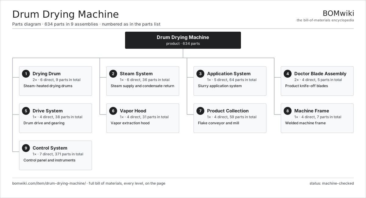
| # | Part | Qty | What it does |
|---|---|---|---|
| 1 | Drying Drum 6 parts | 2× | Steam-heated drying drums |
| 2 | Steam System 6 parts | 1× | Steam supply and condensate return |
| 3 | Application System 5 parts | 1× | Slurry application system |
| 4 | Doctor Blade Assembly 4 parts | 2× | Product knife-off blades |
| 5 | Drive System 4 parts | 1× | Drum drive and gearing |
| 6 | Vapor Hood 4 parts | 1× | Vapor extraction hood |
| 7 | Product Collection 4 parts | 1× | Flake conveyor and mill |
| 8 | Machine Frame 4 parts | 1× | Welded machine frame |
| 9 | Control System 7 parts | 1× | Control panel and instruments |
3D model
No 3D model yet. Have a CAD file of this? Add a 3D model — STL renders right on this page; STEP, FreeCAD, and OpenSCAD sources are welcome too (openly licensed, like all 3D models on BOMwiki).
Build & assembly graph
expand / collapse · shared sub-assemblies converge · links to related products · est. labourTap an assembly to expand/collapse · tap a part to open it · use “Open page” for any node · drag to pan, scroll to zoom.
Bill of materials for Drum Drying Machine
9 top-level lines · 97 rows shown · 634 parts total · indented to 3 levels| # | Item / sub-assembly | Part no. | Qty/assy | Ext. qty | Parts | Type |
|---|---|---|---|---|---|---|
| 1 | Drying Drum 6 parts | ddm-drum-assembly | 2× | 2 | 9 | assembly |
| 1.1 | Drum Shell | ddm-drum-shell | 1× | 2 | · | part |
| 1.2 | Drum Journal | ddm-drum-journal | 2× | 4 | · | part |
| 1.3 | Rotary Steam Joint | ddm-rotary-joint | 1× | 2 | · | part |
| 1.4 | Condensate Siphon | ddm-condensate-scoop | 1× | 2 | · | part |
| 1.5 | Ball Bearing | ball-bearing | 2× | 4 | · | part |
| 1.6 | Oil Seal | oil-seal | 2× | 4 | · | part |
| 2 | Steam System 6 parts | ddm-steam-system | 1× | 1 | 36 | assembly |
| 2.1 | Steam Reducing Valve | ddm-steam-valve | 1× | 1 | · | part |
| 2.2 | Steam Trap | ddm-steam-trap | 2× | 2 | · | part |
| 2.3 | Condensate Receiver | ddm-condensate-tank | 1× | 1 | · | part |
| 2.4 | Condensate Pump 4 parts | ddm-condensate-pump | 1× | 1 | 29 | assembly |
| 2.4.1 | Pump Impeller | ddm-pump-impeller | 1× | 1 | · | part |
| 2.4.2 | Servo Motor 4 parts + deeper › | servo-motor | 1× | 1 | 24 | assembly |
| 2.4.3 | Oil Seal | oil-seal | 2× | 2 | · | part |
| 2.4.4 | Ball Bearing | ball-bearing | 2× | 2 | · | part |
| 2.5 | Steam Piping | ddm-steam-piping | 1× | 1 | · | part |
| 2.6 | Pressure Sensor | pressure-sensor | 2× | 2 | · | part |
| 3 | Application System 5 parts | ddm-applicator | 1× | 1 | 64 | assembly |
| 3.1 | Feed Trough | ddm-feed-trough | 1× | 1 | · | part |
| 3.2 | Spreader Roll | ddm-spreader-roll | 2× | 2 | · | part |
| 3.3 | Slurry Feed Pump 5 parts | ddm-feed-pump | 1× | 1 | 30 | assembly |
| 3.3.1 | Pump Impeller | ddm-pump-impeller | 1× | 1 | · | part |
| 3.3.2 | Servo Motor 4 parts + deeper › | servo-motor | 1× | 1 | 24 | assembly |
| 3.3.3 | Oil Seal | oil-seal | 2× | 2 | · | part |
| 3.3.4 | Ball Bearing | ball-bearing | 2× | 2 | · | part |
| 3.3.5 | O-Ring Set | oring-set | 1× | 1 | · | part |
| 3.4 | Nip Adjuster 3 parts | ddm-nip-adjuster | 1× | 1 | 30 | assembly |
| 3.4.1 | Ball Screw | ball-screw | 2× | 2 | · | part |
| 3.4.2 | Servo Motor 4 parts + deeper › | servo-motor | 1× | 1 | 24 | assembly |
| 3.4.3 | Ball Bearing | ball-bearing | 4× | 4 | · | part |
| 3.5 | Trough Agitator | ddm-agitator | 1× | 1 | · | part |
| 4 | Doctor Blade Assembly 4 parts | ddm-doctor-blade | 2× | 2 | 5 | assembly |
| 4.1 | Scraper Blade | ddm-blade | 1× | 2 | · | part |
| 4.2 | Blade Holder | ddm-blade-holder | 1× | 2 | · | part |
| 4.3 | Blade Spring | ddm-blade-spring | 2× | 4 | · | part |
| 4.4 | Blade Oscillator | ddm-blade-oscillator | 1× | 2 | · | part |
| 5 | Drive System 4 parts | ddm-drive-system | 1× | 1 | 38 | assembly |
| 5.1 | Drive Motor 4 parts | ddm-drive-motor | 1× | 1 | 25 | assembly |
| 5.1.1 | Stator Assembly 3 parts + deeper › | stator-assembly | 1× | 1 | 3 | assembly |
| 5.1.2 | Rotor Assembly 4 parts + deeper › | rotor-assembly | 1× | 1 | 19 | assembly |
| 5.1.3 | Motor Housing | motor-housing | 1× | 1 | · | part |
| 5.1.4 | Ball Bearing | ball-bearing | 2× | 2 | · | part |
| 5.2 | Gear Reducer 5 parts | ddm-gear-reducer | 1× | 1 | 10 | assembly |
| 5.2.1 | Helical Gear Pair | gear-pair | 2× | 2 | · | part |
| 5.2.2 | Gearbox Housing | gearbox-housing | 1× | 1 | · | part |
| 5.2.3 | Ball Bearing | ball-bearing | 4× | 4 | · | part |
| 5.2.4 | Oil Seal | oil-seal | 2× | 2 | · | part |
| 5.2.5 | Gear Oil | gear-oil | 1× | 1 | · | part |
| 5.3 | Bull Gear | ddm-bull-gear | 2× | 2 | · | part |
| 5.4 | Drive Coupling | ddm-drive-coupling | 1× | 1 | · | part |
| 6 | Vapor Hood 4 parts | ddm-vapor-hood | 1× | 1 | 31 | assembly |
| 6.1 | Hood Shell | ddm-hood-shell | 1× | 1 | · | part |
| 6.2 | Exhaust Fan 4 parts | ddm-exhaust-fan | 1× | 1 | 28 | assembly |
| 6.2.1 | Fan Impeller | ddm-fan-impeller | 1× | 1 | · | part |
| 6.2.2 | Servo Motor 4 parts + deeper › | servo-motor | 1× | 1 | 24 | assembly |
| 6.2.3 | Ball Bearing | ball-bearing | 2× | 2 | · | part |
| 6.2.4 | Motor Housing | motor-housing | 1× | 1 | · | part |
| 6.3 | Vapor Duct | ddm-vapor-duct | 1× | 1 | · | part |
| 6.4 | Vapor Condenser | ddm-vapor-condenser | 1× | 1 | · | part |
| 7 | Product Collection 4 parts | ddm-product-collection | 1× | 1 | 59 | assembly |
| 7.1 | Collection Conveyor 3 parts | ddm-collection-conveyor | 1× | 1 | 29 | assembly |
| 7.1.1 | Drive Belt | drive-belt | 1× | 1 | · | part |
| 7.1.2 | Servo Motor 4 parts + deeper › | servo-motor | 1× | 1 | 24 | assembly |
| 7.1.3 | Ball Bearing | ball-bearing | 4× | 4 | · | part |
| 7.2 | Flake Breaker | ddm-flaker | 1× | 1 | · | part |
| 7.3 | Sizing Mill 4 parts | ddm-mill | 1× | 1 | 28 | assembly |
| 7.3.1 | Mill Rotor | ddm-mill-rotor | 1× | 1 | · | part |
| 7.3.2 | Servo Motor 4 parts + deeper › | servo-motor | 1× | 1 | 24 | assembly |
| 7.3.3 | Ball Bearing | ball-bearing | 2× | 2 | · | part |
| 7.3.4 | Mill Screen | ddm-mill-screen | 1× | 1 | · | part |
| 7.4 | Sizing Sifter | ddm-sifter | 1× | 1 | · | part |
| 8 | Machine Frame 4 parts | ddm-frame | 1× | 1 | 7 | assembly |
| 8.1 | Base Frame | ddm-base-frame | 1× | 1 | · | part |
| 8.2 | Bearing Pedestal | ddm-bearing-pedestal | 4× | 4 | · | part |
| 8.3 | Drip Tray | ddm-drip-tray | 1× | 1 | · | part |
| 8.4 | Fastener Set | fastener-set | 1× | 1 | · | part |
| 9 | Control System 7 parts | ddm-control-system | 1× | 1 | 371 | assembly |
| 9.1 | PLC Controller 4 parts | ddm-plc | 1× | 1 | 167 | assembly |
| 9.1.1 | Bare PCB | pcb-bare | 1× | 1 | · | part |
| 9.1.2 | Microcontroller | mcu | 2× | 2 | · | part |
| 9.1.3 | I/O Module | ddm-io-module | 4× | 4 | · | part |
| 9.1.4 | SMD Passive (R/C/L) | smd-passives | 160× | 160 | · | part |
| 9.2 | Operator HMI 4 parts | ddm-hmi | 1× | 1 | 4 | assembly |
| 9.2.1 | LCD Panel | lcd-panel | 1× | 1 | · | part |
| 9.2.2 | Touch Digitizer | touch-digitizer | 1× | 1 | · | part |
| 9.2.3 | Bare PCB | pcb-bare | 1× | 1 | · | part |
| 9.2.4 | Microcontroller | mcu | 1× | 1 | · | part |
| 9.3 | Variable-Frequency Drive 4 parts | ddm-vfd | 2× | 2 | 91 | assembly |
| 9.3.1 | Bare PCB | pcb-bare | 1× | 2 | · | part |
| 9.3.2 | IGBT Power Module | igbt-module | 1× | 2 | · | part |
| 9.3.3 | DC-Link Capacitor | dc-link-cap | 2× | 4 | · | part |
| 9.3.4 | Gate Driver Board 3 parts + deeper › | gate-driver-board | 1× | 2 | 87 | assembly |
| 9.4 | Control Cabinet | ddm-control-cabinet | 1× | 1 | · | part |
| 9.5 | Power Supply | power-supply | 1× | 1 | · | part |
| 9.6 | Temperature Sensor | temperature-sensor | 4× | 4 | · | part |
| 9.7 | Relay | relay | 12× | 12 | · | part |
Related products
same domain, ranked by shared parts Vacuum Belt Dryer
951 parts · shares 28 with this page
Vacuum Belt Dryer
951 parts · shares 28 with this page
 Industrial Freeze Dryer
816 parts · shares 26 with this page
Industrial Freeze Dryer
816 parts · shares 26 with this page
 Fluid Bed Dryer
550 parts · shares 25 with this page
Fluid Bed Dryer
550 parts · shares 25 with this page
 Food Extruder
860 parts · shares 21 with this page
Fruit Grading Line
3,765 parts · shares 23 with this page
Food Extruder
860 parts · shares 21 with this page
Fruit Grading Line
3,765 parts · shares 23 with this page
Sourcing: possible vendors
Prices, MOQ, and lead times are algorithmic estimates, not quotes, and not claims about these companies. Company mappings are curated by keyword; est. price band $1k–$500k. How estimates work| Vendor | HQ | Specialty | MOQ | Lead time |
|---|---|---|---|---|
| gea.com ↗ | Düsseldorf, DE | Process technology | 20 units | 12–20 wks |
| buhlergroup.com ↗ | Uzwil, CH | Food & materials processing | 20 units | 12–20 wks |
| tetrapak.com ↗ | Pully, CH | Food packaging & processing | 20 units | 12–20 wks |
| jbtc.com ↗ | Chicago, US | Food processing equipment | 20 units | 12–20 wks |
| alfalaval.com ↗ | Lund, SE | Heat transfer & separation | 20 units | 12–20 wks |
900-word article