Paddle Mixer
ProductOverview
A paddle mixer blends food ingredients by lifting and folding them with pitched paddles mounted on one or two rotating shafts. The twin-shaft version is the most common in industrial food plants. Two counter-rotating rotors sit in a W-shaped trough and throw material into a brief fluidized zone above the shafts, where particles of different size and density are suspended together for a moment and intermix freely. Because the action is gentle and fast, paddle mixers suit fragile ingredients such as ready-to-eat cereal, granola clusters, frozen vegetables, seasoned snacks, and pet food kibble, where a ribbon or high-shear mixer would crush or break the product.
The defining advantage is speed combined with low shear. A full batch reaches a coefficient of variation below 3 percent in 30 seconds to 4 minutes, far faster than a ribbon blender, because the fluidized zone exposes the entire batch to mixing at once rather than relying on slow conveying flows. The two parts that set the behavior are the Twin Trough and the pair of Paddle Rotor shafts.
Twin trough
The Twin Trough is a W-shaped vessel, effectively two overlapping U-troughs side by side, one for each rotor. The overlap is where the two fluidized zones meet and material crosses from one rotor to the other. The W-Trough Shell and the Trough End Plate pair are 316L stainless steel finished to 0.4 to 0.8 micron Ra. A Replaceable Wear Liner protects the high-wear lower wall and can be replaced without rebuilding the trough. For temperature-sensitive recipes an optional Thermal Jacket with its Jacket Fitting connections circulates steam or chilled water.
Paddle rotors
Each Paddle Rotor carries a row of pitched Pitched Paddle Blade elements held off the Rotor Shaft by Paddle Mounting Arm supports. The paddle pitch angle controls how aggressively material is thrown up and conveyed along the shaft. Paddles near the ends are often angled to draw material inward, keeping the batch from packing against the end plates. The two shafts turn in opposite directions so material rises in the center overlap and falls at the outer walls, creating the figure-eight circulation that gives the machine its fast, uniform result.
Drive and synchronization
The Drive Unit turns both shafts from a single TEFC Motor (10-50 hp) of 10 to 50 hp through a Helical Gearbox reducer. A pair of Synchronizing Gear gears ties the two rotors together so the paddles mesh without colliding, since the swept circles of the two rotors overlap. A Flexible Coupling joins the reducer to the drive shaft and a Variable Frequency Drive sets the rotor speed in the 40 to 120 rpm band. Speed is chosen to put the batch into the fluidized state without throwing product hard enough to damage it.
Bearings and seals
Each shaft end runs in a Shaft Bearing Station with an outboard pillow block and a Air-Purged Shaft Seal. Many food units use an air-purged seal that keeps a slight outward flow of clean air at the shaft penetration, blocking product migration into the bearing and preventing contamination of the batch. The bearings sit outside the product zone for clean inspection and lubrication.
Liquid addition and discharge
A strength of the paddle mixer is its ability to add liquids during mixing. The Liquid Addition System feeds atomizing Atomizing Spray Nozzle heads on a Spray Bar Manifold manifold positioned to spray into the fluidized zone, so droplets coat the suspended particles evenly rather than soaking one spot. A Liquid Metering Pump with a Liquid Flow Meter meters fats, oils, flavors, brines, or coatings up to roughly 30 percent of batch weight. The Solenoid Valve pair switches the spray on and off in step with the mix cycle.
When mixing finishes, the Bomb-Bay Discharge opens. The bomb-bay design uses two full-length Drop Door Panel panels on Door Pivot Shaft pivots, driven open by Pneumatic Cylinder units, so the entire batch drops out in seconds with no residue and no need to keep mixing during discharge. A Door Edge Seal keeps the doors leak-tight while closed.
Cover and controls
The Top Cover seals the top, carrying Feed Port openings, a Vent Port, an Inspection Hatch, and a Cover Interlock Switch interlock. The Control Panel runs the cycle from a PLC Module and HMI Touchscreen, with a motor DC Contactor pair and an E-Stop Button in the safety chain. Recipe storage lets an operator recall the mix time, rotor speed, and liquid dose for each product.
Materials, sanitation, and use
Like other sanitary mixers, the paddle mixer is built from 304 or 316L stainless steel with polished, crevice-free welds in the product zone. The bomb-bay discharge and the smooth W-trough make it straightforward to empty and clean between batches, which matters in plants that run frequent allergen or flavor changeovers. Compared with a ribbon blender, the paddle mixer trades a slightly higher capital cost for much shorter cycle times and gentler handling, so it is chosen wherever throughput and product integrity both matter, such as coating snacks with seasoning or blending delicate cereal mixes.
Paddle Mixer parts and their functions
9 top-level parts · 388 parts in total · full bill of materials below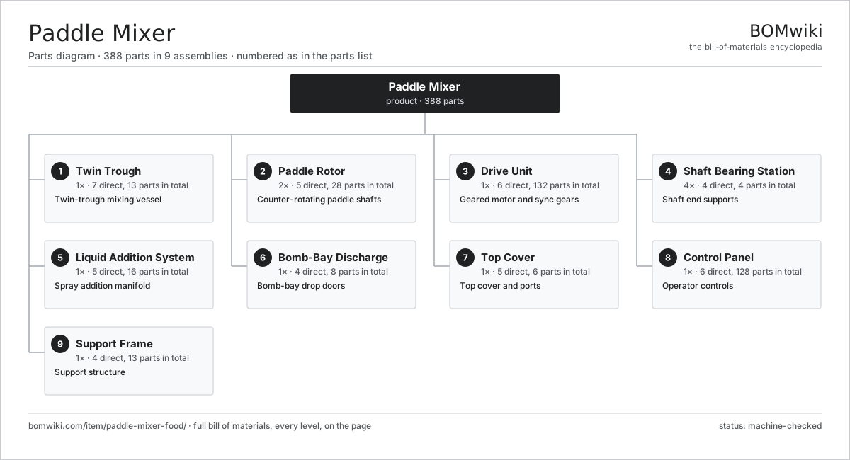
| # | Part | Qty | What it does |
|---|---|---|---|
| 1 | Twin Trough 7 parts | 1× | Twin-trough mixing vessel |
| 2 | Paddle Rotor 5 parts | 2× | Counter-rotating paddle shafts |
| 3 | Drive Unit 6 parts | 1× | Geared motor and sync gears |
| 4 | Shaft Bearing Station 4 parts | 4× | Shaft end supports |
| 5 | Liquid Addition System 5 parts | 1× | Spray addition manifold |
| 6 | Bomb-Bay Discharge 4 parts | 1× | Bomb-bay drop doors |
| 7 | Top Cover 5 parts | 1× | Top cover and ports |
| 8 | Control Panel 6 parts | 1× | Operator controls |
| 9 | Support Frame 4 parts | 1× | Support structure |
3D model
No 3D model yet. Have a CAD file of this? Add a 3D model — STL renders right on this page; STEP, FreeCAD, and OpenSCAD sources are welcome too (openly licensed, like all 3D models on BOMwiki).
Build & assembly graph
expand / collapse · shared sub-assemblies converge · links to related products · est. labourTap an assembly to expand/collapse · tap a part to open it · use “Open page” for any node · drag to pan, scroll to zoom.
Bill of materials for Paddle Mixer
9 top-level lines · 78 rows shown · 388 parts total · indented to 3 levels| # | Item / sub-assembly | Part no. | Qty/assy | Ext. qty | Parts | Type |
|---|---|---|---|---|---|---|
| 1 | Twin Trough 7 parts | paddle-mixer-food-trough | 1× | 1 | 13 | assembly |
| 1.1 | W-Trough Shell | paddle-mixer-food-trough-shell | 1× | 1 | · | part |
| 1.2 | Trough End Plate | paddle-mixer-food-end-plate | 2× | 2 | · | part |
| 1.3 | Thermal Jacket | paddle-mixer-food-jacket | 1× | 1 | · | part |
| 1.4 | Jacket Fitting | paddle-mixer-food-jacket-fitting | 4× | 4 | · | part |
| 1.5 | Replaceable Wear Liner | paddle-mixer-food-wear-liner | 2× | 2 | · | part |
| 1.6 | O-Ring Set | oring-set | 2× | 2 | · | part |
| 1.7 | Fastener Set | fastener-set | 1× | 1 | · | part |
| 2 | Paddle Rotor 5 parts | paddle-mixer-food-rotor | 2× | 2 | 28 | assembly |
| 2.1 | Rotor Shaft | paddle-mixer-food-rotor-shaft | 1× | 2 | · | part |
| 2.2 | Paddle Mounting Arm | paddle-mixer-food-paddle-arm | 12× | 24 | · | part |
| 2.3 | Pitched Paddle Blade | paddle-mixer-food-paddle-blade | 12× | 24 | · | part |
| 2.4 | Shaft Key | paddle-mixer-food-shaft-key | 2× | 4 | · | part |
| 2.5 | Fastener Set | fastener-set | 1× | 2 | · | part |
| 3 | Drive Unit 6 parts | paddle-mixer-food-drive | 1× | 1 | 132 | assembly |
| 3.1 | TEFC Motor (10-50 hp) 5 parts | paddle-mixer-food-motor | 1× | 1 | 26 | assembly |
| 3.1.1 | Stator Assembly 3 parts + deeper › | stator-assembly | 1× | 1 | 3 | assembly |
| 3.1.2 | Rotor Assembly 4 parts + deeper › | rotor-assembly | 1× | 1 | 19 | assembly |
| 3.1.3 | Motor Housing | motor-housing | 1× | 1 | · | part |
| 3.1.4 | Ball Bearing | ball-bearing | 2× | 2 | · | part |
| 3.1.5 | Motor Cooling Fan | paddle-mixer-food-cooling-fan | 1× | 1 | · | part |
| 3.2 | Helical Gearbox 4 parts | gearbox | 1× | 1 | 9 | assembly |
| 3.2.1 | Helical Gear Pair | gear-pair | 2× | 2 | · | part |
| 3.2.2 | Gearbox Housing | gearbox-housing | 1× | 1 | · | part |
| 3.2.3 | Ball Bearing | ball-bearing | 4× | 4 | · | part |
| 3.2.4 | Oil Seal | oil-seal | 2× | 2 | · | part |
| 3.3 | Synchronizing Gear | paddle-mixer-food-sync-gear | 2× | 2 | · | part |
| 3.4 | Flexible Coupling | paddle-mixer-food-coupling | 1× | 1 | · | part |
| 3.5 | Drive Guard | paddle-mixer-food-guard | 1× | 1 | · | part |
| 3.6 | Variable Frequency Drive 4 parts | paddle-mixer-food-vfd | 1× | 1 | 93 | assembly |
| 3.6.1 | Bare PCB | pcb-bare | 1× | 1 | · | part |
| 3.6.2 | IGBT Power Module | igbt-module | 1× | 1 | · | part |
| 3.6.3 | Power Supply | power-supply | 1× | 1 | · | part |
| 3.6.4 | SMD Passive (R/C/L) | smd-passives | 90× | 90 | · | part |
| 4 | Shaft Bearing Station 4 parts | paddle-mixer-food-bearing-station | 4× | 4 | 4 | assembly |
| 4.1 | Pillow Block Housing | paddle-mixer-food-pillow-block | 1× | 4 | · | part |
| 4.2 | Ball Bearing | ball-bearing | 1× | 4 | · | part |
| 4.3 | Air-Purged Shaft Seal | paddle-mixer-food-shaft-seal | 1× | 4 | · | part |
| 4.4 | Oil Seal | oil-seal | 1× | 4 | · | part |
| 5 | Liquid Addition System 5 parts | paddle-mixer-food-liquid-system | 1× | 1 | 16 | assembly |
| 5.1 | Spray Bar Manifold | paddle-mixer-food-spray-bar | 2× | 2 | · | part |
| 5.2 | Atomizing Spray Nozzle | paddle-mixer-food-spray-nozzle | 8× | 8 | · | part |
| 5.3 | Liquid Metering Pump 3 parts | paddle-mixer-food-liquid-pump | 1× | 1 | 3 | assembly |
| 5.3.1 | Pump Head | paddle-mixer-food-pump-head | 1× | 1 | · | part |
| 5.3.2 | Pump Motor | paddle-mixer-food-pump-motor | 1× | 1 | · | part |
| 5.3.3 | O-Ring Set | oring-set | 1× | 1 | · | part |
| 5.4 | Liquid Flow Meter | paddle-mixer-food-flow-meter | 1× | 1 | · | part |
| 5.5 | Solenoid Valve | paddle-mixer-food-solenoid-valve | 2× | 2 | · | part |
| 6 | Bomb-Bay Discharge 4 parts | paddle-mixer-food-discharge | 1× | 1 | 8 | assembly |
| 6.1 | Drop Door Panel | paddle-mixer-food-drop-door | 2× | 2 | · | part |
| 6.2 | Door Pivot Shaft | paddle-mixer-food-door-shaft | 2× | 2 | · | part |
| 6.3 | Pneumatic Cylinder | pneumatic-cylinder | 2× | 2 | · | part |
| 6.4 | Door Edge Seal | paddle-mixer-food-door-seal | 2× | 2 | · | part |
| 7 | Top Cover 5 parts | paddle-mixer-food-cover | 1× | 1 | 6 | assembly |
| 7.1 | Cover Panel | paddle-mixer-food-cover-panel | 1× | 1 | · | part |
| 7.2 | Feed Port | paddle-mixer-food-feed-port | 2× | 2 | · | part |
| 7.3 | Vent Port | paddle-mixer-food-vent-port | 1× | 1 | · | part |
| 7.4 | Inspection Hatch | paddle-mixer-food-inspection-hatch | 1× | 1 | · | part |
| 7.5 | Cover Interlock Switch | paddle-mixer-food-cover-switch | 1× | 1 | · | part |
| 8 | Control Panel 6 parts | paddle-mixer-food-control-panel | 1× | 1 | 128 | assembly |
| 8.1 | NEMA 4X Enclosure | paddle-mixer-food-enclosure | 1× | 1 | · | part |
| 8.2 | PLC Module 4 parts | paddle-mixer-food-plc | 1× | 1 | 120 | assembly |
| 8.2.1 | Bare PCB | pcb-bare | 1× | 1 | · | part |
| 8.2.2 | Microcontroller | mcu | 1× | 1 | · | part |
| 8.2.3 | Relay | relay | 8× | 8 | · | part |
| 8.2.4 | SMD Passive (R/C/L) | smd-passives | 110× | 110 | · | part |
| 8.3 | HMI Touchscreen 3 parts | paddle-mixer-food-hmi | 1× | 1 | 3 | assembly |
| 8.3.1 | LCD Panel | lcd-panel | 1× | 1 | · | part |
| 8.3.2 | Bare PCB | pcb-bare | 1× | 1 | · | part |
| 8.3.3 | Microcontroller | mcu | 1× | 1 | · | part |
| 8.4 | DC Contactor | contactor | 2× | 2 | · | part |
| 8.5 | E-Stop Button | paddle-mixer-food-estop | 1× | 1 | · | part |
| 8.6 | Wire Bundle | wire-bundle | 1× | 1 | · | part |
| 9 | Support Frame 4 parts | paddle-mixer-food-frame | 1× | 1 | 13 | assembly |
| 9.1 | Support Leg | paddle-mixer-food-leg | 4× | 4 | · | part |
| 9.2 | Cross Brace | paddle-mixer-food-cross-brace | 4× | 4 | · | part |
| 9.3 | Leveling Foot | paddle-mixer-food-foot | 4× | 4 | · | part |
| 9.4 | Fastener Set | fastener-set | 1× | 1 | · | part |
Related products
same domain, ranked by shared parts Continuous Cooker
789 parts · shares 22 with this page
Continuous Cooker
789 parts · shares 22 with this page
 Food Extruder
860 parts · shares 21 with this page
Spray Drying Tower
1,040 parts · shares 20 with this page
Food Extruder
860 parts · shares 21 with this page
Spray Drying Tower
1,040 parts · shares 20 with this page
 Fluid Bed Dryer
550 parts · shares 17 with this page
Candy Depositing Line
223 parts · shares 12 with this page
Fluid Bed Dryer
550 parts · shares 17 with this page
Candy Depositing Line
223 parts · shares 12 with this page
Sourcing: possible vendors
Prices, MOQ, and lead times are algorithmic estimates, not quotes, and not claims about these companies. Company mappings are curated by keyword; est. price band $1k–$500k. How estimates work| Vendor | HQ | Specialty | MOQ | Lead time |
|---|---|---|---|---|
| gea.com ↗ | Düsseldorf, DE | Process technology | 20 units | 12–20 wks |
| buhlergroup.com ↗ | Uzwil, CH | Food & materials processing | 20 units | 12–20 wks |
| tetrapak.com ↗ | Pully, CH | Food packaging & processing | 20 units | 12–20 wks |
| jbtc.com ↗ | Chicago, US | Food processing equipment | 20 units | 12–20 wks |
| alfalaval.com ↗ | Lund, SE | Heat transfer & separation | 20 units | 12–20 wks |
939-word article