Industrial Freeze Dryer
ProductOverview
An industrial freeze dryer, also called a lyophilizer, removes water from food by sublimation: the food is frozen solid, then the surrounding pressure is lowered so far that the ice turns straight to vapor without ever becoming liquid. Because the product stays frozen and is never heated above a gentle temperature, its structure, colour, flavour, and nutrients are preserved far better than with hot-air or drum drying. The dry product is light and porous, so it rehydrates quickly, which is why freeze drying is used for instant coffee, fruit pieces, ready-meal vegetables, herbs, and high-value ingredients.
The machine is a set of cold and vacuum systems working together. Frozen trays sit on the Shelf Stack inside the Drying Chamber, the Vacuum System pumps the chamber down, the Heat Transfer Loop supplies just enough heat to sublime the ice, and the Ice Condenser captures the vapor by freezing it back to ice on a very cold surface. A Refrigeration System plant provides the cold for both the shelves and the condenser, and a Control System runs the long cycle automatically.
The drying cycle
A freeze-drying run has three stages. First the product is frozen on the shelves, often in the machine itself, until all its water is solid ice. Then comes primary drying: the chamber is evacuated and the shelves are gently warmed so the ice sublimes, vapor leaving the product and travelling to the condenser. Most of the water leaves here, slowly, because each gram of ice needs a large amount of heat to sublime and the vapor must flow through the deep vacuum. Finally, secondary drying raises the shelf temperature a little more to drive off the last bound water that did not freeze, bringing the product down to one to three percent moisture. The whole cycle commonly runs a day or two, which is why throughput per machine is modest and the product is high-value.
Shelves and heat transfer
The Shelf Stack does double duty. Each hollow Process Shelf carries Product Tray trays and circulates a silicone heat transfer fluid fed by the Shelf Manifold. At the start the Heat Transfer Loop runs that fluid cold, through the Fluid Cooler linked to the refrigeration plant, to freeze the product. During drying the Fluid Heater warms the same fluid so the shelves deliver the heat of sublimation. The control here is delicate: too much heat and the product warms past the point where the frozen structure collapses or melts back, ruining it; too little and the run takes even longer. Product probes among the Temperature Sensor sensors watch the coldest spots so the recipe can push heat as hard as is safe. In pharmaceutical use the Shelf Ram also compresses the stack to seat vial stoppers before the vacuum is broken.
Vacuum and the ice condenser
Sublimation only happens at low pressure, so the Vacuum System is central. A Roughing Pump pulls the chamber from atmosphere down toward its base pressure, and a Roots Booster Roots blower then holds the deep vacuum and handles the large volume of low-pressure vapor coming off the product. A Vacuum Gauge reading is one of the two key process variables. The vapor itself is not pumped away as gas; instead it travels to the Ice Condenser, whose Condenser Coil is held tens of degrees colder than the shelves, around -60 to -80 C. The vapor freezes onto it as ice, which both keeps the chamber pressure low and protects the vacuum pumps from the huge water load. The condenser must stay colder than the product, or the vapor would not flow toward it, so its temperature drives the whole process.
Refrigeration
The Refrigeration System plant supplies all the cold. Reaching condenser temperatures below -60 C usually needs a cascade or two-stage arrangement, with Refrigeration Compressor compressors, a Refrigerant Condenser to reject heat, Expansion Valve devices to produce the cold, and a Refrigerant Receiver to hold the charge. The same plant, through the Fluid Cooler, also pre-freezes the shelves at the start of the cycle, so the refrigeration capacity is sized for the larger of the freezing and condensing duties.
Cleaning, control, and structure
Between batches the Clean & Defrost System defrosts the condenser, melting the accumulated ice out through the Defrost Drain, and washes the chamber and shelves through CIP Nozzle sprays so the next product starts clean. The Control System PLC runs the freeze, primary, and secondary drying steps from a stored recipe, holding shelf temperature and chamber pressure on profile, watching the product probes to decide when drying is complete, and logging the full batch record that food and pharma quality systems require. All of the vessels, refrigeration, and pumps are carried on the Frame & Structure skid, which keeps the heavy vacuum chamber and condenser aligned and supports the insulated piping that ties the cold and vacuum systems together.
Industrial Freeze Dryer parts and their functions
9 top-level parts · 816 parts in total · full bill of materials below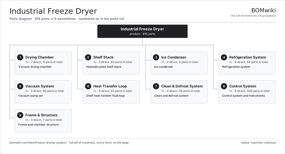
| # | Part | Qty | What it does |
|---|---|---|---|
| 1 | Drying Chamber 7 parts | 1× | Vacuum drying chamber |
| 2 | Shelf Stack 5 parts | 1× | Heated/cooled shelf stack |
| 3 | Ice Condenser 4 parts | 1× | Ice condenser |
| 4 | Refrigeration System 6 parts | 1× | Refrigeration system |
| 5 | Vacuum System 5 parts | 1× | Vacuum pump set |
| 6 | Heat Transfer Loop 5 parts | 1× | Shelf heat transfer fluid loop |
| 7 | Clean & Defrost System 4 parts | 1× | Clean and defrost system |
| 8 | Control System 6 parts | 1× | Control system and instruments |
| 9 | Frame & Structure 4 parts | 1× | Frame and chamber structure |
3D model
No 3D model yet. Have a CAD file of this? Add a 3D model — STL renders right on this page; STEP, FreeCAD, and OpenSCAD sources are welcome too (openly licensed, like all 3D models on BOMwiki).
Build & assembly graph
expand / collapse · shared sub-assemblies converge · links to related products · est. labourTap an assembly to expand/collapse · tap a part to open it · use “Open page” for any node · drag to pan, scroll to zoom.
Bill of materials for Industrial Freeze Dryer
9 top-level lines · 90 rows shown · 816 parts total · indented to 3 levels| # | Item / sub-assembly | Part no. | Qty/assy | Ext. qty | Parts | Type |
|---|---|---|---|---|---|---|
| 1 | Drying Chamber 7 parts | fds-drying-chamber | 1× | 1 | 11 | assembly |
| 1.1 | Chamber Shell | fds-chamber-shell | 1× | 1 | · | part |
| 1.2 | Chamber Door | fds-chamber-door | 1× | 1 | · | part |
| 1.3 | Door Seal | fds-door-seal | 1× | 1 | · | part |
| 1.4 | Insulation Jacket | fds-chamber-insulation | 1× | 1 | · | part |
| 1.5 | Sight Port | fds-sight-port | 2× | 2 | · | part |
| 1.6 | Vacuum Port | fds-vacuum-port | 4× | 4 | · | part |
| 1.7 | Fastener Set | fastener-set | 1× | 1 | · | part |
| 2 | Shelf Stack 5 parts | fds-shelf-stack | 1× | 1 | 80 | assembly |
| 2.1 | Process Shelf | fds-shelf | 12× | 12 | · | part |
| 2.2 | Shelf Manifold | fds-shelf-manifold | 1× | 1 | · | part |
| 2.3 | Shelf Ram 3 parts | fds-shelf-ram | 1× | 1 | 31 | assembly |
| 2.3.1 | Hydraulic Cylinder | fds-hydraulic-cylinder | 1× | 1 | · | part |
| 2.3.2 | Hydraulic Pump 3 parts + deeper › | fds-hydraulic-pump | 1× | 1 | 28 | assembly |
| 2.3.3 | O-Ring Set | oring-set | 2× | 2 | · | part |
| 2.4 | Product Tray | fds-product-tray | 24× | 24 | · | part |
| 2.5 | Temperature Sensor | temperature-sensor | 12× | 12 | · | part |
| 3 | Ice Condenser 4 parts | fds-condenser | 1× | 1 | 4 | assembly |
| 3.1 | Condenser Coil | fds-condenser-coil | 1× | 1 | · | part |
| 3.2 | Condenser Shell | fds-condenser-shell | 1× | 1 | · | part |
| 3.3 | Isolation Valve | fds-isolation-valve | 1× | 1 | · | part |
| 3.4 | Defrost Drain | fds-defrost-drain | 1× | 1 | · | part |
| 4 | Refrigeration System 6 parts | fds-refrigeration | 1× | 1 | 69 | assembly |
| 4.1 | Refrigeration Compressor 5 parts | fds-compressor | 2× | 2 | 30 | assembly |
| 4.1.1 | Compressor Block | fds-compressor-block | 1× | 2 | · | part |
| 4.1.2 | Servo Motor 4 parts + deeper › | servo-motor | 1× | 2 | 24 | assembly |
| 4.1.3 | Ball Bearing | ball-bearing | 2× | 4 | · | part |
| 4.1.4 | Oil Seal | oil-seal | 2× | 4 | · | part |
| 4.1.5 | O-Ring Set | oring-set | 1× | 2 | · | part |
| 4.2 | Refrigerant Condenser | fds-refrig-condenser | 1× | 1 | · | part |
| 4.3 | Expansion Valve | fds-expansion-valve | 2× | 2 | · | part |
| 4.4 | Refrigerant Receiver | fds-refrig-receiver | 1× | 1 | · | part |
| 4.5 | Refrigerant Piping | fds-refrig-piping | 1× | 1 | · | part |
| 4.6 | Pressure Sensor | pressure-sensor | 4× | 4 | · | part |
| 5 | Vacuum System 5 parts | fds-vacuum-system | 1× | 1 | 66 | assembly |
| 5.1 | Roughing Pump 4 parts | fds-rough-pump | 1× | 1 | 29 | assembly |
| 5.1.1 | Pump Rotor | fds-pump-rotor | 1× | 1 | · | part |
| 5.1.2 | Servo Motor 4 parts + deeper › | servo-motor | 1× | 1 | 24 | assembly |
| 5.1.3 | Oil Seal | oil-seal | 2× | 2 | · | part |
| 5.1.4 | Ball Bearing | ball-bearing | 2× | 2 | · | part |
| 5.2 | Roots Booster 4 parts | fds-booster-pump | 1× | 1 | 31 | assembly |
| 5.2.1 | Helical Gear Pair | gear-pair | 1× | 1 | · | part |
| 5.2.2 | Servo Motor 4 parts + deeper › | servo-motor | 1× | 1 | 24 | assembly |
| 5.2.3 | Ball Bearing | ball-bearing | 4× | 4 | · | part |
| 5.2.4 | Oil Seal | oil-seal | 2× | 2 | · | part |
| 5.3 | Vacuum Valve | fds-vacuum-valve | 3× | 3 | · | part |
| 5.4 | Vacuum Gauge | fds-vacuum-gauge | 2× | 2 | · | part |
| 5.5 | Cold Trap | fds-cold-trap | 1× | 1 | · | part |
| 6 | Heat Transfer Loop 5 parts | fds-heating-system | 1× | 1 | 33 | assembly |
| 6.1 | Fluid Pump 4 parts | fds-htf-pump | 1× | 1 | 29 | assembly |
| 6.1.1 | Servo Motor 4 parts + deeper › | servo-motor | 1× | 1 | 24 | assembly |
| 6.1.2 | Oil Seal | oil-seal | 2× | 2 | · | part |
| 6.1.3 | Ball Bearing | ball-bearing | 2× | 2 | · | part |
| 6.1.4 | O-Ring Set | oring-set | 1× | 1 | · | part |
| 6.2 | Fluid Heater | fds-htf-heater | 1× | 1 | · | part |
| 6.3 | Fluid Cooler | fds-htf-cooler | 1× | 1 | · | part |
| 6.4 | Expansion Tank | fds-htf-tank | 1× | 1 | · | part |
| 6.5 | Fluid Piping | fds-htf-piping | 1× | 1 | · | part |
| 7 | Clean & Defrost System 4 parts | fds-cip-system | 1× | 1 | 38 | assembly |
| 7.1 | CIP Nozzle | fds-cip-nozzle | 8× | 8 | · | part |
| 7.2 | CIP Pump 3 parts | fds-cip-pump | 1× | 1 | 28 | assembly |
| 7.2.1 | Servo Motor 4 parts + deeper › | servo-motor | 1× | 1 | 24 | assembly |
| 7.2.2 | Oil Seal | oil-seal | 2× | 2 | · | part |
| 7.2.3 | Ball Bearing | ball-bearing | 2× | 2 | · | part |
| 7.3 | Defrost Heater | fds-defrost-heater | 1× | 1 | · | part |
| 7.4 | CIP Tank | fds-cip-tank | 1× | 1 | · | part |
| 8 | Control System 6 parts | fds-control-system | 1× | 1 | 508 | assembly |
| 8.1 | PLC Controller 4 parts | fds-plc | 1× | 1 | 209 | assembly |
| 8.1.1 | Bare PCB | pcb-bare | 1× | 1 | · | part |
| 8.1.2 | Microcontroller | mcu | 2× | 2 | · | part |
| 8.1.3 | I/O Module | fds-io-module | 6× | 6 | · | part |
| 8.1.4 | SMD Passive (R/C/L) | smd-passives | 200× | 200 | · | part |
| 8.2 | Operator HMI 4 parts | fds-hmi | 1× | 1 | 4 | assembly |
| 8.2.1 | LCD Panel | lcd-panel | 1× | 1 | · | part |
| 8.2.2 | Touch Digitizer | touch-digitizer | 1× | 1 | · | part |
| 8.2.3 | Bare PCB | pcb-bare | 1× | 1 | · | part |
| 8.2.4 | Microcontroller | mcu | 1× | 1 | · | part |
| 8.3 | Control Cabinet | fds-control-cabinet | 1× | 1 | · | part |
| 8.4 | Power Supply | power-supply | 1× | 1 | · | part |
| 8.5 | Variable-Frequency Drive 4 parts | fds-vfd | 3× | 3 | 91 | assembly |
| 8.5.1 | Bare PCB | pcb-bare | 1× | 3 | · | part |
| 8.5.2 | IGBT Power Module | igbt-module | 1× | 3 | · | part |
| 8.5.3 | DC-Link Capacitor | dc-link-cap | 2× | 6 | · | part |
| 8.5.4 | Gate Driver Board 3 parts + deeper › | gate-driver-board | 1× | 3 | 87 | assembly |
| 8.6 | Relay | relay | 20× | 20 | · | part |
| 9 | Frame & Structure 4 parts | fds-frame | 1× | 1 | 7 | assembly |
| 9.1 | Skid Frame | fds-skid-frame | 1× | 1 | · | part |
| 9.2 | Chamber Cradle | fds-chamber-support | 1× | 1 | · | part |
| 9.3 | Access Panel | fds-access-panel | 4× | 4 | · | part |
| 9.4 | Fastener Set | fastener-set | 1× | 1 | · | part |
Related products
same domain, ranked by shared parts Drum Drying Machine
634 parts · shares 26 with this page
Spray Drying Tower
1,040 parts · shares 26 with this page
Drum Drying Machine
634 parts · shares 26 with this page
Spray Drying Tower
1,040 parts · shares 26 with this page
 Vacuum Belt Dryer
951 parts · shares 26 with this page
Vacuum Belt Dryer
951 parts · shares 26 with this page
 Fluid Bed Dryer
550 parts · shares 24 with this page
Fruit Grading Line
3,765 parts · shares 21 with this page
Fluid Bed Dryer
550 parts · shares 24 with this page
Fruit Grading Line
3,765 parts · shares 21 with this page
 Grain Color Sorter
3,056 parts · shares 20 with this page
Grain Color Sorter
3,056 parts · shares 20 with this page
Sourcing: possible vendors
Prices, MOQ, and lead times are algorithmic estimates, not quotes, and not claims about these companies. Company mappings are curated by keyword; est. price band $1k–$500k. How estimates work| Vendor | HQ | Specialty | MOQ | Lead time |
|---|---|---|---|---|
| gea.com ↗ | Düsseldorf, DE | Process technology | 20 units | 12–20 wks |
| buhlergroup.com ↗ | Uzwil, CH | Food & materials processing | 20 units | 12–20 wks |
| tetrapak.com ↗ | Pully, CH | Food packaging & processing | 20 units | 12–20 wks |
| jbtc.com ↗ | Chicago, US | Food processing equipment | 20 units | 12–20 wks |
| alfalaval.com ↗ | Lund, SE | Heat transfer & separation | 20 units | 12–20 wks |
838-word article