Fluid Bed Dryer
ProductOverview
A fluid bed dryer dries loose granular food by blowing hot air up through it fast enough to lift the particles so they float and tumble in the stream. In that fluidized state the bed behaves like a gently boiling liquid: every granule is surrounded by moving hot air, so heat reaches it from all sides and the moisture it gives off is carried away at once. The result is fast, even drying at a relatively low air temperature, which suits granulated products such as instant drink powders, breakfast cereal pieces, spice granules, milk and whey powders, and pharmaceutical-style food granules.
The core of the machine is the Process Chamber sitting on the Air Distributor. Conditioned air from the Air Handling Unit unit is pushed up through the distributor by the Process Fan, fluidizes the bed, and leaves through the Exhaust Filter, which keeps the fine particles in. The Product Handling section loads and unloads the granules, an optional Top-Spray System lets the same machine granulate or coat, and the Control System runs the batch and the safety interlocks.
How fluidization works
Fluidization depends on getting the air speed right. Below a certain velocity the air just percolates through a static bed; above it the drag on the particles balances their weight and the bed lifts and starts to bubble and circulate. The job of the Air Distributor is to make this happen evenly across the whole bowl. Its Distributor Plate splits the inlet air into many fine jets, fed from a Inlet Plenum below that levels the pressure so no part of the bed gets more air than another. A Retention Mesh over the plate keeps the granules from falling through. If the distribution is uneven, part of the bed sits dead while another part blows a channel, and drying becomes patchy, so the plate pattern is matched to the product.
Conditioning the air
The Air Handling Unit unit decides how much drying the air can do. Incoming air first passes the Inlet Filter Bank so no outside dust reaches the food, then the Air Heater warms it to the set inlet temperature, usually a modest 40-120 C because the rapid air contact does the work rather than high heat. A Dehumidifier Coil coil is often fitted ahead of the heater to drop the air dew point, so the drying rate stays the same whether the day is dry or humid. Holding the inlet conditions steady is what makes one batch match the next.
Keeping the product in
Because fine particles are easily carried up by the air, the Exhaust Filter sits above the bed in the Expansion Chamber, where the air has slowed enough for most particles to fall back. The Filter Bag sleeves catch whatever dust is still entrained, and a Bag Shaker or Pulse Valve periodically knocks the collected fines back down into the bed so nothing is lost and the filter does not blind. This internal filtration is what lets the dryer run on fine powders without a separate dust collector.
Driving and moving the product
The Process Fan supplies the airflow for the whole loop and is sized for the pressure drop across the distributor, the bed, and the filters together. Running it induced-draft, drawing through the chamber, keeps the inside under slight negative pressure so dust stays contained. A Variable-Frequency Drive varies the Fan Motor speed to set fluidization precisely. Product comes in through the Feed Device and leaves through the Discharge Valve onto a Discharge Conveyor and a Sifter; on a batch machine the Bowl Lift simply lowers the whole bowl so it can be filled, emptied, or swapped.
Granulating and coating
With the Top-Spray System fitted, the dryer does more than dry. A Spray Nozzle on a Spray Lance sprays a binder solution onto the fluidized particles while they dry: the droplets land, stick particles together, and dry, building larger, free-flowing granules. Spray a coating liquid instead and the same action lays an even film on each particle, used for taste-masking, controlled release, or protecting a sensitive ingredient. The Spray Pump meters the liquid and the Atomizing Air Control sets the droplet size, so one machine can dry, granulate, or coat depending on the recipe.
Control and structure
The Control System PLC sets the inlet temperature and the fan speed and reads the bed and outlet temperatures, with the outlet condition the practical signal of dryness: while the bed is wet the outlet stays cool and humid, and as it dries the outlet temperature rises toward the inlet. The control ends the batch on a target outlet temperature or humidity and runs the explosion-safety interlocks that drying fine organic powder demands. Everything is carried on the Frame & Support, which stacks the chamber sections over the plenum and filter housing, supports the Process Ducting air loop, and provides the bowl lift and seals that let the machine be opened and washed between products with the Temperature Sensor probes and wash-in-place sprays built in.
Fluid Bed Dryer parts and their functions
9 top-level parts · 550 parts in total · full bill of materials below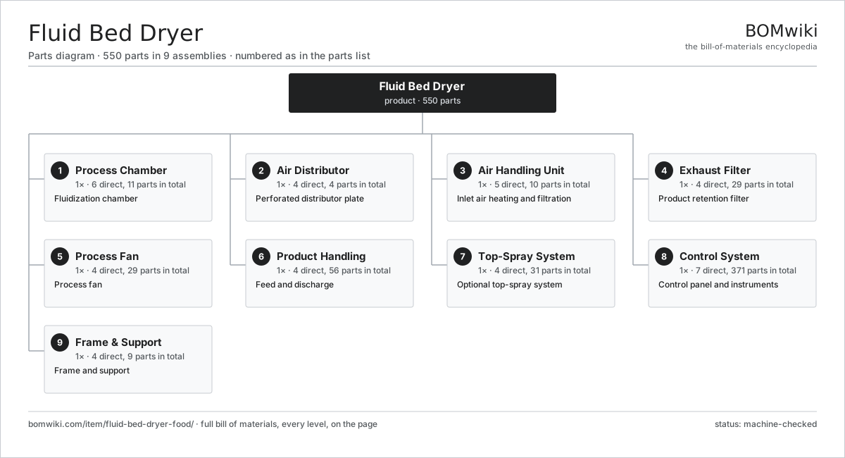
| # | Part | Qty | What it does |
|---|---|---|---|
| 1 | Process Chamber 6 parts | 1× | Fluidization chamber |
| 2 | Air Distributor 4 parts | 1× | Perforated distributor plate |
| 3 | Air Handling Unit 5 parts | 1× | Inlet air heating and filtration |
| 4 | Exhaust Filter 4 parts | 1× | Product retention filter |
| 5 | Process Fan 4 parts | 1× | Process fan |
| 6 | Product Handling 4 parts | 1× | Feed and discharge |
| 7 | Top-Spray System 4 parts | 1× | Optional top-spray system |
| 8 | Control System 7 parts | 1× | Control panel and instruments |
| 9 | Frame & Support 4 parts | 1× | Frame and support |
3D model
No 3D model yet. Have a CAD file of this? Add a 3D model — STL renders right on this page; STEP, FreeCAD, and OpenSCAD sources are welcome too (openly licensed, like all 3D models on BOMwiki).
Build & assembly graph
expand / collapse · shared sub-assemblies converge · links to related products · est. labourTap an assembly to expand/collapse · tap a part to open it · use “Open page” for any node · drag to pan, scroll to zoom.
Bill of materials for Fluid Bed Dryer
9 top-level lines · 82 rows shown · 550 parts total · indented to 3 levels| # | Item / sub-assembly | Part no. | Qty/assy | Ext. qty | Parts | Type |
|---|---|---|---|---|---|---|
| 1 | Process Chamber 6 parts | fbd-process-chamber | 1× | 1 | 11 | assembly |
| 1.1 | Product Container | fbd-product-container | 1× | 1 | · | part |
| 1.2 | Expansion Chamber | fbd-expansion-chamber | 1× | 1 | · | part |
| 1.3 | Chamber Seal | fbd-chamber-seal | 2× | 2 | · | part |
| 1.4 | Sight Glass | fbd-sight-glass | 2× | 2 | · | part |
| 1.5 | CIP Nozzle | fbd-cip-nozzle | 4× | 4 | · | part |
| 1.6 | Fastener Set | fastener-set | 1× | 1 | · | part |
| 2 | Air Distributor 4 parts | fbd-air-distributor | 1× | 1 | 4 | assembly |
| 2.1 | Distributor Plate | fbd-distributor-plate | 1× | 1 | · | part |
| 2.2 | Retention Mesh | fbd-distributor-mesh | 1× | 1 | · | part |
| 2.3 | Inlet Plenum | fbd-plenum | 1× | 1 | · | part |
| 2.4 | Distributor Gasket | fbd-distributor-gasket | 1× | 1 | · | part |
| 3 | Air Handling Unit 5 parts | fbd-air-handling | 1× | 1 | 10 | assembly |
| 3.1 | Inlet Filter Bank | fbd-inlet-filter | 1× | 1 | · | part |
| 3.2 | Air Heater 3 parts | fbd-air-heater | 1× | 1 | 4 | assembly |
| 3.2.1 | Heating Element | heating-element | 2× | 2 | · | part |
| 3.2.2 | Heater Coil | fbd-heater-coil | 1× | 1 | · | part |
| 3.2.3 | Temperature Sensor | temperature-sensor | 1× | 1 | · | part |
| 3.3 | Dehumidifier Coil | fbd-dehumidifier | 1× | 1 | · | part |
| 3.4 | Inlet Damper | fbd-inlet-damper | 1× | 1 | · | part |
| 3.5 | Temperature Sensor | temperature-sensor | 3× | 3 | · | part |
| 4 | Exhaust Filter 4 parts | fbd-exhaust-filter | 1× | 1 | 29 | assembly |
| 4.1 | Filter Bag | fbd-filter-bag | 12× | 12 | · | part |
| 4.2 | Bag Cage | fbd-filter-cage | 12× | 12 | · | part |
| 4.3 | Bag Shaker | fbd-shaker | 1× | 1 | · | part |
| 4.4 | Pulse Valve | fbd-pulse-valve | 4× | 4 | · | part |
| 5 | Process Fan 4 parts | fbd-fan-system | 1× | 1 | 29 | assembly |
| 5.1 | Fan Impeller | fbd-fan-impeller | 1× | 1 | · | part |
| 5.2 | Fan Motor 4 parts | fbd-fan-motor | 1× | 1 | 25 | assembly |
| 5.2.1 | Stator Assembly 3 parts + deeper › | stator-assembly | 1× | 1 | 3 | assembly |
| 5.2.2 | Rotor Assembly 4 parts + deeper › | rotor-assembly | 1× | 1 | 19 | assembly |
| 5.2.3 | Motor Housing | motor-housing | 1× | 1 | · | part |
| 5.2.4 | Ball Bearing | ball-bearing | 2× | 2 | · | part |
| 5.3 | Fan Housing | fbd-fan-housing | 1× | 1 | · | part |
| 5.4 | Ball Bearing | ball-bearing | 2× | 2 | · | part |
| 6 | Product Handling 4 parts | fbd-product-handling | 1× | 1 | 56 | assembly |
| 6.1 | Feed Device 3 parts | fbd-feed-device | 1× | 1 | 27 | assembly |
| 6.1.1 | Servo Motor 4 parts + deeper › | servo-motor | 1× | 1 | 24 | assembly |
| 6.1.2 | Ball Bearing | ball-bearing | 2× | 2 | · | part |
| 6.1.3 | Feed Screw | fbd-feed-screw | 1× | 1 | · | part |
| 6.2 | Discharge Valve | fbd-discharge-valve | 1× | 1 | · | part |
| 6.3 | Discharge Conveyor 3 parts | fbd-discharge-conveyor | 1× | 1 | 27 | assembly |
| 6.3.1 | Drive Belt | drive-belt | 1× | 1 | · | part |
| 6.3.2 | Servo Motor 4 parts + deeper › | servo-motor | 1× | 1 | 24 | assembly |
| 6.3.3 | Ball Bearing | ball-bearing | 2× | 2 | · | part |
| 6.4 | Sifter | fbd-sifter | 1× | 1 | · | part |
| 7 | Top-Spray System 4 parts | fbd-spray-system | 1× | 1 | 31 | assembly |
| 7.1 | Spray Nozzle | fbd-spray-nozzle | 2× | 2 | · | part |
| 7.2 | Spray Pump 3 parts | fbd-spray-pump | 1× | 1 | 27 | assembly |
| 7.2.1 | Servo Motor 4 parts + deeper › | servo-motor | 1× | 1 | 24 | assembly |
| 7.2.2 | Ball Bearing | ball-bearing | 2× | 2 | · | part |
| 7.2.3 | O-Ring Set | oring-set | 1× | 1 | · | part |
| 7.3 | Atomizing Air Control | fbd-atomizing-air | 1× | 1 | · | part |
| 7.4 | Spray Lance | fbd-spray-lance | 1× | 1 | · | part |
| 8 | Control System 7 parts | fbd-control-system | 1× | 1 | 371 | assembly |
| 8.1 | PLC Controller 4 parts | fbd-plc | 1× | 1 | 167 | assembly |
| 8.1.1 | Bare PCB | pcb-bare | 1× | 1 | · | part |
| 8.1.2 | Microcontroller | mcu | 2× | 2 | · | part |
| 8.1.3 | I/O Module | fbd-io-module | 4× | 4 | · | part |
| 8.1.4 | SMD Passive (R/C/L) | smd-passives | 160× | 160 | · | part |
| 8.2 | Operator HMI 4 parts | fbd-hmi | 1× | 1 | 4 | assembly |
| 8.2.1 | LCD Panel | lcd-panel | 1× | 1 | · | part |
| 8.2.2 | Touch Digitizer | touch-digitizer | 1× | 1 | · | part |
| 8.2.3 | Bare PCB | pcb-bare | 1× | 1 | · | part |
| 8.2.4 | Microcontroller | mcu | 1× | 1 | · | part |
| 8.3 | Variable-Frequency Drive 4 parts | fbd-vfd | 2× | 2 | 91 | assembly |
| 8.3.1 | Bare PCB | pcb-bare | 1× | 2 | · | part |
| 8.3.2 | IGBT Power Module | igbt-module | 1× | 2 | · | part |
| 8.3.3 | DC-Link Capacitor | dc-link-cap | 2× | 4 | · | part |
| 8.3.4 | Gate Driver Board 3 parts + deeper › | gate-driver-board | 1× | 2 | 87 | assembly |
| 8.4 | Control Cabinet | fbd-control-cabinet | 1× | 1 | · | part |
| 8.5 | Power Supply | power-supply | 1× | 1 | · | part |
| 8.6 | Pressure Sensor | pressure-sensor | 4× | 4 | · | part |
| 8.7 | Relay | relay | 12× | 12 | · | part |
| 9 | Frame & Support 4 parts | fbd-frame | 1× | 1 | 9 | assembly |
| 9.1 | Support Frame | fbd-support-frame | 1× | 1 | · | part |
| 9.2 | Bowl Lift 3 parts | fbd-bowl-lift | 1× | 1 | 6 | assembly |
| 9.2.1 | Pneumatic Cylinder | pneumatic-cylinder | 2× | 2 | · | part |
| 9.2.2 | Linear Guide Rail | linear-guide | 2× | 2 | · | part |
| 9.2.3 | Connector | connector | 2× | 2 | · | part |
| 9.3 | Process Ducting | fbd-ducting | 1× | 1 | · | part |
| 9.4 | Fastener Set | fastener-set | 1× | 1 | · | part |
Related products
same domain, ranked by shared parts Drum Drying Machine
634 parts · shares 25 with this page
Drum Drying Machine
634 parts · shares 25 with this page
 Vacuum Belt Dryer
951 parts · shares 25 with this page
Vacuum Belt Dryer
951 parts · shares 25 with this page
 Industrial Freeze Dryer
816 parts · shares 24 with this page
Scraped Cooking Kettle
334 parts · shares 18 with this page
Industrial Freeze Dryer
816 parts · shares 24 with this page
Scraped Cooking Kettle
334 parts · shares 18 with this page
 Paddle Mixer
388 parts · shares 17 with this page
Paddle Mixer
388 parts · shares 17 with this page
Sourcing: possible vendors
Prices, MOQ, and lead times are algorithmic estimates, not quotes, and not claims about these companies. Company mappings are curated by keyword; est. price band $1k–$500k. How estimates work| Vendor | HQ | Specialty | MOQ | Lead time |
|---|---|---|---|---|
| gea.com ↗ | Düsseldorf, DE | Process technology | 20 units | 12–20 wks |
| buhlergroup.com ↗ | Uzwil, CH | Food & materials processing | 20 units | 12–20 wks |
| tetrapak.com ↗ | Pully, CH | Food packaging & processing | 20 units | 12–20 wks |
| jbtc.com ↗ | Chicago, US | Food processing equipment | 20 units | 12–20 wks |
| alfalaval.com ↗ | Lund, SE | Heat transfer & separation | 20 units | 12–20 wks |
867-word article