Hydrostatic Sterilizer
ProductOverview
A hydrostatic sterilizer is a continuous retort that cooks sealed cans of food at sterilizing temperature without ever using a pressure door. Instead of locking cans inside a pressure vessel the way a batch retort does, it balances the steam pressure with two tall columns of water. Cans ride on carriers up one water column, through a central steam chamber held above 116 C, then down a second water column and into a cooling section. Because the water columns seal the steam by their own weight, cans enter and leave at atmospheric pressure through open ends while the steam dome stays pressurized. The machine runs without stopping, which is why high-volume canneries use it for products like peas, corn, pet food, soup, and evaporated milk where the line never pauses.
The whole machine is built around the Tower Structure, a steel frame tall enough to hold the Water Seal Legs and the Steam Dome at the right height. Cans move on the Carrier Conveyor, get cooled in the Cooling Section, and the whole sequence is timed by the Conveyor Drive System under the Control System.
How the water legs hold pressure
The principle that makes the machine work lives in the Water Seal Legs. Steam at 1 bar gauge needs roughly 10 metres of water to balance it, so each leg stands about 11 to 13 metres tall. The Infeed Water Leg carries cans up from the open infeed into the pressurized dome, and the Discharge Water Leg carries them back down to atmosphere. Water in the infeed leg is hot near the top and cooler at the bottom, so the can warms gradually as it climbs, which avoids the thermal shock that can buckle an end or strip a seam. The Water Leg Shell is welded stainless steel, lined with a Leg Splash Liner where the carriers rub, and fitted with a Water Level Probe at several heights so the control system knows the water column is at the correct level. An Overflow Weir sets the top level precisely, because a leg that is too short would let steam blow through and a leg that is too tall would flood the dome.
The steam dome
The Steam Dome is the sterilizing chamber. Saturated steam fills the Steam Dome Shell, a code-stamped pressure vessel, and a Steam Distributor Manifold spreads it evenly so there are no cold pockets where a can could be under-processed. Temperature is the single most important measurement here, so several Thermocouple Probe probes and a Pressure Sensor feed the controller, which trims a Steam Control Valve to hold the set point within a fraction of a degree. Condensate that forms as steam gives up its heat drains through a Condensate Steam Trap, and a Safety Relief Valve protects the shell against overpressure. The dome is wrapped in Dome Insulation Cladding to keep heat in and to keep the surface safe to touch. A can spends most of its dwell time crossing the dome, and the chain speed set by the drive decides how long that is.
Moving the cans
Cans never travel loose. They sit in the Can Carrier Bar pockets that span between two strands of Carrier Chain Strand. Each chain is built from a Conveyor Chain Link, a Chain Pin, and a Chain Roller repeated thousands of times into an endless loop that climbs the infeed leg, crosses the dome, descends the discharge leg, and threads the cooling section before returning. The chain wraps a Drive Sprocket at every turn and slides along a Chain Guide Rail on the straight runs. Because the loop is so long and stretches in service, a Chain Take-Up Unit keeps it tensioned. The carrier bars hold the cans firmly enough that they neither float in the water legs nor rattle in the steam, and the pitch between bars is matched to the can diameter so each carrier holds a full row.
Cooling and water handling
After sterilizing, a can is still near process temperature and must be brought down before it leaves, or the contents keep cooking and the label will not stick. The Cooling Section runs the cans through a Cooling Water Canal and under a Spray Header Pipe fitted with many a Cooling Spray Nozzle, driven by a Cooling Water Pump. Cooling water is chlorinated, because the seam is briefly its most vulnerable as the can contracts and the contents pull a partial vacuum, so any water drawn past the seam must be safe. The hot leg water itself is kept at temperature by the Water Heating & Recirculation, where a Recirculation Pump pushes water through a Steam Heat Exchanger that adds steam heat, and a Inline Strainer keeps debris out of the pumps and nozzles.
Drive, control, and can handling
Everything moves at one synchronized speed set by the Conveyor Drive System. A Drive Motor turns through a Gearbox Housing and a Helical Gear Pair onto the Drive Head Shaft, with a Variable Frequency Drive setting the chain speed and therefore the dwell time. The Control System is the part that makes the machine legal to operate, since a sterilizer is a critical control point. A PLC Control Cabinet runs the logic, the operator works through an HMI Terminal, and a Process Data Recorder keeps the temperature record that a food safety auditor will read. Filled cans enter through the Infeed & Discharge section, where an Infeed Star Wheel times each can into a carrier and an Discharge Star Wheel lifts each sterilized can back out to the Can Feed Conveyor. The cans that come off this machine are commercially sterile and shelf-stable for years, which is the whole point of running them through several minutes at well above the boiling point of water.
Hydrostatic Sterilizer parts and their functions
9 top-level parts · 9,247 parts in total · full bill of materials below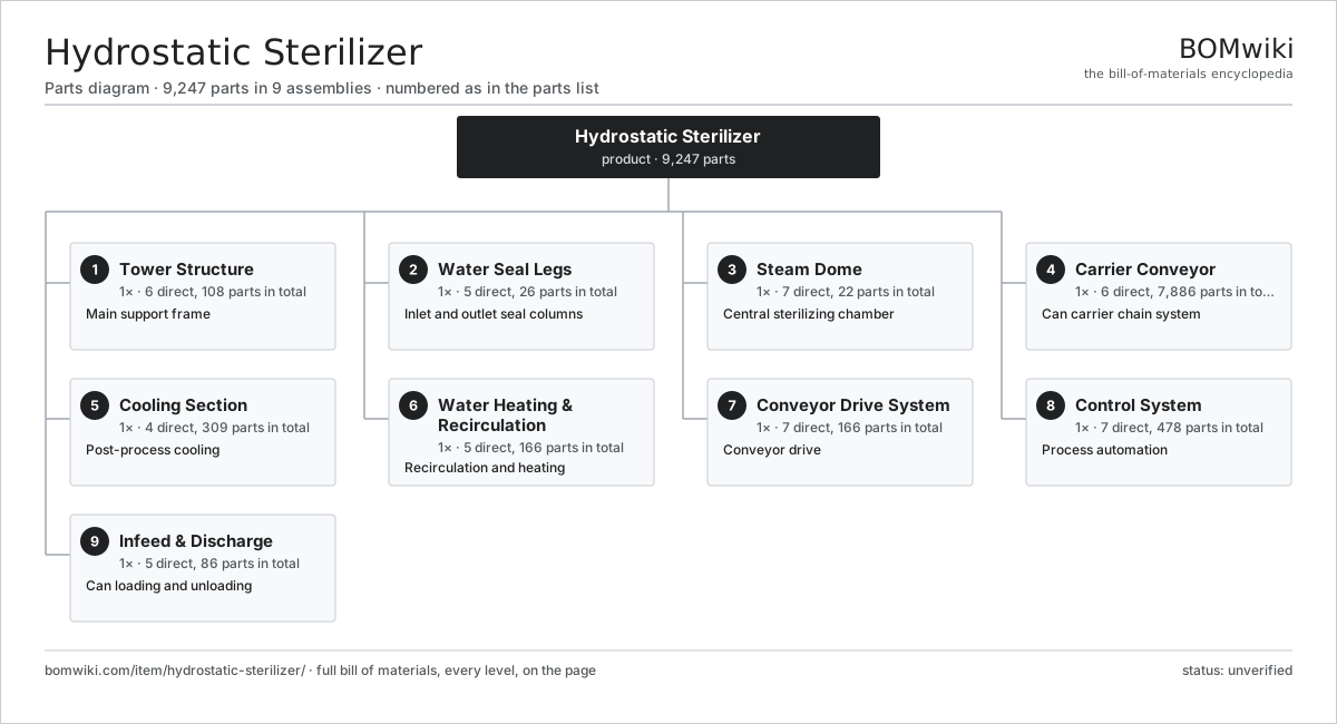
| # | Part | Qty | What it does |
|---|---|---|---|
| 1 | Tower Structure 6 parts | 1× | Main support frame |
| 2 | Water Seal Legs 5 parts | 1× | Inlet and outlet seal columns |
| 3 | Steam Dome 7 parts | 1× | Central sterilizing chamber |
| 4 | Carrier Conveyor 6 parts | 1× | Can carrier chain system |
| 5 | Cooling Section 4 parts | 1× | Post-process cooling |
| 6 | Water Heating & Recirculation 5 parts | 1× | Recirculation and heating |
| 7 | Conveyor Drive System 7 parts | 1× | Conveyor drive |
| 8 | Control System 7 parts | 1× | Process automation |
| 9 | Infeed & Discharge 5 parts | 1× | Can loading and unloading |
3D model
No 3D model yet. Have a CAD file of this? Add a 3D model — STL renders right on this page; STEP, FreeCAD, and OpenSCAD sources are welcome too (openly licensed, like all 3D models on BOMwiki).
Build & assembly graph
expand / collapse · shared sub-assemblies converge · links to related products · est. labourTap an assembly to expand/collapse · tap a part to open it · use “Open page” for any node · drag to pan, scroll to zoom.
Bill of materials for Hydrostatic Sterilizer
9 top-level lines · 132 rows shown · 9,247 parts total · indented to 3 levels| # | Item / sub-assembly | Part no. | Qty/assy | Ext. qty | Parts | Type |
|---|---|---|---|---|---|---|
| 1 | Tower Structure 6 parts | hydrostatic-sterilizer-tower-structure | 1× | 1 | 108 | assembly |
| 1.1 | Structural Steel Column | hydrostatic-sterilizer-column-steel | 8× | 8 | · | part |
| 1.2 | Cross Bracing Member | hydrostatic-sterilizer-cross-bracing | 24× | 24 | · | part |
| 1.3 | Access Platform 3 parts | hydrostatic-sterilizer-access-platform | 6× | 6 | 11 | assembly |
| 1.3.1 | Steel Grating Panel | hydrostatic-sterilizer-grating-panel | 4× | 24 | · | part |
| 1.3.2 | Handrail Section | hydrostatic-sterilizer-handrail | 6× | 36 | · | part |
| 1.3.3 | Fastener Set | fastener-set | 1× | 6 | · | part |
| 1.4 | Stair Tower | hydrostatic-sterilizer-stair-tower | 1× | 1 | · | part |
| 1.5 | Anchor Base Plate | hydrostatic-sterilizer-base-plate | 8× | 8 | · | part |
| 1.6 | Fastener Set | fastener-set | 1× | 1 | · | part |
| 2 | Water Seal Legs 5 parts | hydrostatic-sterilizer-water-legs | 1× | 1 | 26 | assembly |
| 2.1 | Infeed Water Leg 3 parts | hydrostatic-sterilizer-infeed-leg | 1× | 1 | 8 | assembly |
| 2.1.1 | Water Leg Shell | hydrostatic-sterilizer-leg-shell | 1× | 1 | · | part |
| 2.1.2 | Leg Flange | hydrostatic-sterilizer-leg-flange | 4× | 4 | · | part |
| 2.1.3 | Thermocouple Probe | hydrostatic-sterilizer-thermocouple | 3× | 3 | · | part |
| 2.2 | Discharge Water Leg 3 parts | hydrostatic-sterilizer-discharge-leg | 1× | 1 | 8 | assembly |
| 2.2.1 | Water Leg Shell | hydrostatic-sterilizer-leg-shell | 1× | 1 | · | part |
| 2.2.2 | Leg Flange | hydrostatic-sterilizer-leg-flange | 4× | 4 | · | part |
| 2.2.3 | Thermocouple Probe | hydrostatic-sterilizer-thermocouple | 3× | 3 | · | part |
| 2.3 | Leg Splash Liner | hydrostatic-sterilizer-leg-liner | 4× | 4 | · | part |
| 2.4 | Water Level Probe | hydrostatic-sterilizer-level-probe | 4× | 4 | · | part |
| 2.5 | Overflow Weir | hydrostatic-sterilizer-overflow-weir | 2× | 2 | · | part |
| 3 | Steam Dome 7 parts | hydrostatic-sterilizer-steam-dome | 1× | 1 | 22 | assembly |
| 3.1 | Steam Dome Shell | hydrostatic-sterilizer-dome-shell | 1× | 1 | · | part |
| 3.2 | Steam Distributor Manifold | hydrostatic-sterilizer-steam-distributor | 4× | 4 | · | part |
| 3.3 | Steam Control Valve 3 parts | hydrostatic-sterilizer-steam-valve | 2× | 2 | 3 | assembly |
| 3.3.1 | Valve Body | hydrostatic-sterilizer-valve-body | 1× | 2 | · | part |
| 3.3.2 | Pneumatic Valve Actuator | hydrostatic-sterilizer-valve-actuator | 1× | 2 | · | part |
| 3.3.3 | O-Ring Set | oring-set | 1× | 2 | · | part |
| 3.4 | Pressure Sensor | pressure-sensor | 4× | 4 | · | part |
| 3.5 | Safety Relief Valve | hydrostatic-sterilizer-safety-valve | 2× | 2 | · | part |
| 3.6 | Dome Insulation Cladding | hydrostatic-sterilizer-dome-insulation | 1× | 1 | · | part |
| 3.7 | Condensate Steam Trap | hydrostatic-sterilizer-condensate-trap | 4× | 4 | · | part |
| 4 | Carrier Conveyor 6 parts | hydrostatic-sterilizer-carrier-conveyor | 1× | 1 | 7,886 | assembly |
| 4.1 | Carrier Chain Strand 3 parts | hydrostatic-sterilizer-carrier-chain | 2× | 2 | 3,600 | assembly |
| 4.1.1 | Conveyor Chain Link | hydrostatic-sterilizer-chain-link | 1200× | 2,400 | · | part |
| 4.1.2 | Chain Pin | hydrostatic-sterilizer-chain-pin | 1200× | 2,400 | · | part |
| 4.1.3 | Chain Roller | hydrostatic-sterilizer-chain-roller | 1200× | 2,400 | · | part |
| 4.2 | Can Carrier Bar | hydrostatic-sterilizer-carrier-bar | 600× | 600 | · | part |
| 4.3 | Drive Sprocket | hydrostatic-sterilizer-chain-sprocket | 12× | 12 | · | part |
| 4.4 | Chain Guide Rail | hydrostatic-sterilizer-chain-guide | 40× | 40 | · | part |
| 4.5 | Chain Take-Up Unit 3 parts | hydrostatic-sterilizer-take-up-unit | 2× | 2 | 5 | assembly |
| 4.5.1 | Take-Up Adjusting Screw | hydrostatic-sterilizer-take-up-screw | 1× | 2 | · | part |
| 4.5.2 | Ball Bearing | ball-bearing | 2× | 4 | · | part |
| 4.5.3 | Coil Spring | coil-spring | 2× | 4 | · | part |
| 4.6 | Ball Bearing | ball-bearing | 24× | 24 | · | part |
| 5 | Cooling Section 4 parts | hydrostatic-sterilizer-cooling-section | 1× | 1 | 309 | assembly |
| 5.1 | Cooling Water Canal | hydrostatic-sterilizer-cooling-canal | 1× | 1 | · | part |
| 5.2 | Spray Header Pipe | hydrostatic-sterilizer-spray-header | 12× | 12 | · | part |
| 5.3 | Cooling Spray Nozzle | hydrostatic-sterilizer-spray-nozzle | 240× | 240 | · | part |
| 5.4 | Cooling Water Pump 6 parts | hydrostatic-sterilizer-cooling-pump | 2× | 2 | 28 | assembly |
| 5.4.1 | Pump Casing | hydrostatic-sterilizer-pump-casing | 1× | 2 | · | part |
| 5.4.2 | Pump Impeller | hydrostatic-sterilizer-pump-impeller | 1× | 2 | · | part |
| 5.4.3 | Ball Bearing | ball-bearing | 2× | 4 | · | part |
| 5.4.4 | Oil Seal | oil-seal | 2× | 4 | · | part |
| 5.4.5 | Stator Assembly 3 parts + deeper › | stator-assembly | 1× | 2 | 3 | assembly |
| 5.4.6 | Rotor Assembly 4 parts + deeper › | rotor-assembly | 1× | 2 | 19 | assembly |
| 6 | Water Heating & Recirculation 5 parts | hydrostatic-sterilizer-water-system | 1× | 1 | 166 | assembly |
| 6.1 | Recirculation Pump 6 parts | hydrostatic-sterilizer-recirc-pump | 2× | 2 | 28 | assembly |
| 6.1.1 | Pump Casing | hydrostatic-sterilizer-pump-casing | 1× | 2 | · | part |
| 6.1.2 | Pump Impeller | hydrostatic-sterilizer-pump-impeller | 1× | 2 | · | part |
| 6.1.3 | Ball Bearing | ball-bearing | 2× | 4 | · | part |
| 6.1.4 | Oil Seal | oil-seal | 2× | 4 | · | part |
| 6.1.5 | Stator Assembly 3 parts + deeper › | stator-assembly | 1× | 2 | 3 | assembly |
| 6.1.6 | Rotor Assembly 4 parts + deeper › | rotor-assembly | 1× | 2 | 19 | assembly |
| 6.2 | Steam Heat Exchanger 3 parts | hydrostatic-sterilizer-heat-exchanger | 1× | 1 | 83 | assembly |
| 6.2.1 | Heat Exchanger Plate | hydrostatic-sterilizer-exchanger-plate | 80× | 80 | · | part |
| 6.2.2 | Exchanger Frame | hydrostatic-sterilizer-exchanger-frame | 1× | 1 | · | part |
| 6.2.3 | O-Ring Set | oring-set | 2× | 2 | · | part |
| 6.3 | Process Pipe Manifold | hydrostatic-sterilizer-pipe-manifold | 1× | 1 | · | part |
| 6.4 | Inline Strainer | hydrostatic-sterilizer-strainer | 2× | 2 | · | part |
| 6.5 | Process Valve 3 parts | hydrostatic-sterilizer-process-valve | 8× | 8 | 3 | assembly |
| 6.5.1 | Valve Body | hydrostatic-sterilizer-valve-body | 1× | 8 | · | part |
| 6.5.2 | Pneumatic Valve Actuator | hydrostatic-sterilizer-valve-actuator | 1× | 8 | · | part |
| 6.5.3 | O-Ring Set | oring-set | 1× | 8 | · | part |
| 7 | Conveyor Drive System 7 parts | hydrostatic-sterilizer-drive-system | 1× | 1 | 166 | assembly |
| 7.1 | Drive Motor 4 parts | hydrostatic-sterilizer-drive-motor | 1× | 1 | 25 | assembly |
| 7.1.1 | Stator Assembly 3 parts + deeper › | stator-assembly | 1× | 1 | 3 | assembly |
| 7.1.2 | Rotor Assembly 4 parts + deeper › | rotor-assembly | 1× | 1 | 19 | assembly |
| 7.1.3 | Ball Bearing | ball-bearing | 2× | 2 | · | part |
| 7.1.4 | Oil Seal | oil-seal | 1× | 1 | · | part |
| 7.2 | Gearbox Housing | gearbox-housing | 1× | 1 | · | part |
| 7.3 | Helical Gear Pair | gear-pair | 2× | 2 | · | part |
| 7.4 | Drive Head Shaft | hydrostatic-sterilizer-drive-shaft | 2× | 2 | · | part |
| 7.5 | Drive Belt | drive-belt | 2× | 2 | · | part |
| 7.6 | Ball Bearing | ball-bearing | 8× | 8 | · | part |
| 7.7 | Variable Frequency Drive 4 parts | hydrostatic-sterilizer-vfd | 1× | 1 | 126 | assembly |
| 7.7.1 | Bare PCB | pcb-bare | 1× | 1 | · | part |
| 7.7.2 | Power Supply | power-supply | 1× | 1 | · | part |
| 7.7.3 | Relay | relay | 4× | 4 | · | part |
| 7.7.4 | SMD Passive (R/C/L) | smd-passives | 120× | 120 | · | part |
| 8 | Control System 7 parts | hydrostatic-sterilizer-control-system | 1× | 1 | 478 | assembly |
| 8.1 | PLC Control Cabinet 6 parts | hydrostatic-sterilizer-plc-cabinet | 1× | 1 | 336 | assembly |
| 8.1.1 | Bare PCB | pcb-bare | 2× | 2 | · | part |
| 8.1.2 | Microcontroller | mcu | 4× | 4 | · | part |
| 8.1.3 | Power Supply | power-supply | 2× | 2 | · | part |
| 8.1.4 | Relay | relay | 24× | 24 | · | part |
| 8.1.5 | SMD Passive (R/C/L) | smd-passives | 300× | 300 | · | part |
| 8.1.6 | Sheet Metal Panel | sheet-panel | 4× | 4 | · | part |
| 8.2 | HMI Terminal 4 parts | hydrostatic-sterilizer-hmi-terminal | 1× | 1 | 4 | assembly |
| 8.2.1 | LCD Panel | lcd-panel | 1× | 1 | · | part |
| 8.2.2 | Bare PCB | pcb-bare | 1× | 1 | · | part |
| 8.2.3 | Microcontroller | mcu | 1× | 1 | · | part |
| 8.2.4 | Power Supply | power-supply | 1× | 1 | · | part |
| 8.3 | Pressure Sensor | pressure-sensor | 6× | 6 | · | part |
| 8.4 | Thermocouple Probe | hydrostatic-sterilizer-thermocouple | 8× | 8 | · | part |
| 8.5 | Process Data Recorder 4 parts | hydrostatic-sterilizer-recorder | 1× | 1 | 63 | assembly |
| 8.5.1 | Bare PCB | pcb-bare | 1× | 1 | · | part |
| 8.5.2 | Microcontroller | mcu | 1× | 1 | · | part |
| 8.5.3 | LCD Panel | lcd-panel | 1× | 1 | · | part |
| 8.5.4 | SMD Passive (R/C/L) | smd-passives | 60× | 60 | · | part |
| 8.6 | Wire Bundle | wire-bundle | 1× | 1 | · | part |
| 8.7 | Connector | connector | 60× | 60 | · | part |
| 9 | Infeed & Discharge 5 parts | hydrostatic-sterilizer-infeed-discharge | 1× | 1 | 86 | assembly |
| 9.1 | Infeed Star Wheel 3 parts | hydrostatic-sterilizer-infeed-star | 1× | 1 | 15 | assembly |
| 9.1.1 | Star Wheel Disc | hydrostatic-sterilizer-star-disc | 1× | 1 | · | part |
| 9.1.2 | Ball Bearing | ball-bearing | 2× | 2 | · | part |
| 9.1.3 | Star Pocket Insert | hydrostatic-sterilizer-pocket-insert | 12× | 12 | · | part |
| 9.2 | Discharge Star Wheel 3 parts | hydrostatic-sterilizer-discharge-star | 1× | 1 | 15 | assembly |
| 9.2.1 | Star Wheel Disc | hydrostatic-sterilizer-star-disc | 1× | 1 | · | part |
| 9.2.2 | Ball Bearing | ball-bearing | 2× | 2 | · | part |
| 9.2.3 | Star Pocket Insert | hydrostatic-sterilizer-pocket-insert | 12× | 12 | · | part |
| 9.3 | Can Feed Conveyor 3 parts | hydrostatic-sterilizer-feed-conveyor | 1× | 1 | 6 | assembly |
| 9.3.1 | Tabletop Feed Belt | hydrostatic-sterilizer-feed-belt | 1× | 1 | · | part |
| 9.3.2 | Drive Belt | drive-belt | 1× | 1 | · | part |
| 9.3.3 | Ball Bearing | ball-bearing | 4× | 4 | · | part |
| 9.4 | Timing Screw | hydrostatic-sterilizer-timing-screw | 2× | 2 | · | part |
| 9.5 | Servo Motor 4 parts | servo-motor | 2× | 2 | 24 | assembly |
| 9.5.1 | Stator Assembly 3 parts + deeper › | stator-assembly | 1× | 2 | 3 | assembly |
| 9.5.2 | Rotor Assembly 4 parts + deeper › | rotor-assembly | 1× | 2 | 19 | assembly |
| 9.5.3 | Encoder | encoder | 1× | 2 | · | part |
| 9.5.4 | Motor Housing | motor-housing | 1× | 2 | · | part |
Related products
same domain, ranked by shared parts Industrial Coffee Grinder
788 parts · shares 26 with this page
Industrial Coffee Grinder
788 parts · shares 26 with this page
 Sausage Linking Machine
518 parts · shares 26 with this page
Sausage Linking Machine
518 parts · shares 26 with this page
 Flour Milling Plant
2,774 parts · shares 25 with this page
Fruit Grading Line
3,765 parts · shares 25 with this page
Industrial Pellet Mill
1,087 parts · shares 25 with this page
Flour Milling Plant
2,774 parts · shares 25 with this page
Fruit Grading Line
3,765 parts · shares 25 with this page
Industrial Pellet Mill
1,087 parts · shares 25 with this page
Sourcing: possible vendors
Prices, MOQ, and lead times are algorithmic estimates, not quotes, and not claims about these companies. Company mappings are curated by keyword; est. price band $1k–$500k. How estimates work| Vendor | HQ | Specialty | MOQ | Lead time |
|---|---|---|---|---|
| gea.com ↗ | Düsseldorf, DE | Process technology | 20 units | 12–20 wks |
| buhlergroup.com ↗ | Uzwil, CH | Food & materials processing | 20 units | 12–20 wks |
| tetrapak.com ↗ | Pully, CH | Food packaging & processing | 20 units | 12–20 wks |
| jbtc.com ↗ | Chicago, US | Food processing equipment | 20 units | 12–20 wks |
| alfalaval.com ↗ | Lund, SE | Heat transfer & separation | 20 units | 12–20 wks |
1,027-word article