Continuous Butter Churn
ProductOverview
A continuous butter churn turns ripened cream into packed butter in one unbroken flow, replacing the batch churn that once dominated dairies. The dominant design is the Fritz process, named after the German engineer who developed it, and it is the layout described here. Cream enters at one end, passes through a high-speed churning cylinder, a separation and drying section, and a kneading section, and leaves the far end as a continuous strand of finished butter ready for packaging. A mid-size machine produces 500 to 5000 kg/h, far more than a batch churn of comparable footprint, and it holds composition close enough to feed automatic forming and wrapping lines without an operator adjusting every batch.
The feedstock is ripened cream standardized to 40 to 42 percent fat. Lower fat cream churns slowly and yields wet grains, while higher fat cream is hard to pump and inverts before it is fully cooled. The Cream Feed Assembly assembly holds this cream in a Balance Tank and meters it through a Cream Feed Pump at a rate read by a Cream Flow Meter. Steady feed is the single most important input variable, because every downstream section is tuned to a fixed residence time.
Churning and phase inversion
The heart of the machine is the Churning Cylinder. Inside the jacketed Churning Barrel, a Beater Shaft spins at 1400 to 2900 rpm and drives a set of Beater Blade elements through the cream. The mechanical shear breaks the fat globule membranes so that liquid fat coalesces and the oil-in-water emulsion inverts to a water-in-oil structure: butter grains suspended in buttermilk. This phase inversion takes only 1.5 to 3 seconds. The Cylinder Cooling Jacket carries chilled water to remove the heat of churning and hold the grains firm, since soft grains smear instead of separating cleanly. A Beater Shaft Seal keeps product off the bearings, and the high rotational speed makes shaft balance with the Balance Weight set important for bearing life.
Buttermilk separation
From the cylinder the grain and buttermilk mixture drops into the Separation Section. Here the Separation Auger moves the grains slowly along a Drain Cylinder while a Buttermilk Drain Screen passes buttermilk to the Buttermilk Outlet. Recovered buttermilk goes to powder drying or animal feed rather than waste. A bank of Grain Paddle elements gently presses the grains together so they begin to form a coherent mass instead of remaining as loose pellets. Drainage at this stage sets the starting moisture for the rest of the line, so the auger speed and screen open area are matched to the cream feed rate.
Squeeze drying
The agglomerated grains pass into the Squeeze-Drying Section, where a pair of counter-rotating Squeeze Auger elements force the mass through a tapering Squeeze Barrel. The rising pressure presses residual buttermilk out through a Squeeze Drain Plate on each side. A Moisture Sensor reads the butter as it leaves this section, giving the control system an early reading before water is added back. Squeeze drying brings the butter below its final moisture target so that the dosing section can correct it upward with precision rather than trying to remove water later.
Working and dosing
The Working Section is where butter gets its final texture and composition. The Working Auger pair pushes the butter through a series of Perforated Working Plate elements separated by Mixing Baffle units. Forcing the butter through the small holes shears the water into droplets fine enough that the finished product is dense and free of visible moisture, which also slows microbial growth. A Vacuum Chamber pulls entrained air out so the butter has the right density and color. Alongside the working augers, the Dosing and Injection Section injects measured water through a Water Dosing Pump to bring moisture to the legal 16 percent maximum, and brine through a Brine Dosing Pump for salted grades. The dosing pumps are slaved to the cream flow signal and the moisture reading so composition stays on target as feed conditions drift.
Cooling, drive, and outlet
Every barrel that needs temperature held carries a jacket fed from the Cooling System, with a Coolant Pump circulating chilled water through a Coolant Manifold. Each process section runs at its own speed, so the Drive System uses a high-power Beater Drive Motor for the cylinder and separate geared drives for the augers. The finished butter leaves through the Outlet and Extruder, where an Extruder Cone consolidates it into a continuous strand and a Back-Pressure Valve holds the working section under pressure for uniform texture. Shared components carry the loads: Ball Bearing sets support the shafts, Oil Seal elements protect the bearings, and a Helical Gear Pair in each gearbox sets auger speed.
Control and hygiene
A Control Panel coordinates the whole line. Its PLC reads the flow meter, moisture sensor, and temperature probes, then trims the dosing pumps and drive speeds through a set of Variable Frequency Drive units. The operator watches rates and composition on the Operator Touchscreen. Because the machine runs for hours between stops, all wetted parts are 316L stainless polished for clean-in-place washing, and an O-Ring Set of food-grade seals lets the sections be opened for inspection without damaging the sanitary surfaces. Hygienic guarding and a stainless Support Frame complete a unit that meets dairy sanitation rules while running continuously.
Continuous Butter Churn parts and their functions
11 top-level parts · 275 parts in total · full bill of materials below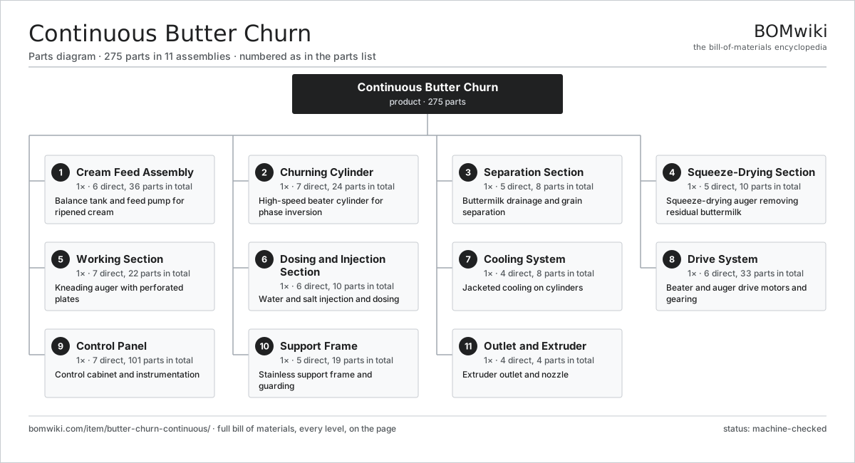
| # | Part | Qty | What it does |
|---|---|---|---|
| 1 | Cream Feed Assembly 6 parts | 1× | Balance tank and feed pump for ripened cream |
| 2 | Churning Cylinder 7 parts | 1× | High-speed beater cylinder for phase inversion |
| 3 | Separation Section 5 parts | 1× | Buttermilk drainage and grain separation |
| 4 | Squeeze-Drying Section 5 parts | 1× | Squeeze-drying auger removing residual buttermilk |
| 5 | Working Section 7 parts | 1× | Kneading auger with perforated plates |
| 6 | Dosing and Injection Section 6 parts | 1× | Water and salt injection and dosing |
| 7 | Cooling System 4 parts | 1× | Jacketed cooling on cylinders |
| 8 | Drive System 6 parts | 1× | Beater and auger drive motors and gearing |
| 9 | Control Panel 7 parts | 1× | Control cabinet and instrumentation |
| 10 | Support Frame 5 parts | 1× | Stainless support frame and guarding |
| 11 | Outlet and Extruder 4 parts | 1× | Extruder outlet and nozzle |
3D model
No 3D model yet. Have a CAD file of this? Add a 3D model — STL renders right on this page; STEP, FreeCAD, and OpenSCAD sources are welcome too (openly licensed, like all 3D models on BOMwiki).
Build & assembly graph
expand / collapse · shared sub-assemblies converge · links to related products · est. labourTap an assembly to expand/collapse · tap a part to open it · use “Open page” for any node · drag to pan, scroll to zoom.
Bill of materials for Continuous Butter Churn
11 top-level lines · 93 rows shown · 275 parts total · indented to 3 levels| # | Item / sub-assembly | Part no. | Qty/assy | Ext. qty | Parts | Type |
|---|---|---|---|---|---|---|
| 1 | Cream Feed Assembly 6 parts | butter-churn-continuous-cream-feed | 1× | 1 | 36 | assembly |
| 1.1 | Balance Tank | butter-churn-continuous-balance-tank | 1× | 1 | · | part |
| 1.2 | Cream Feed Pump 5 parts | butter-churn-continuous-feed-pump | 1× | 1 | 31 | assembly |
| 1.2.1 | Pump Rotor | butter-churn-continuous-pump-rotor | 2× | 2 | · | part |
| 1.2.2 | Pump Casing | butter-churn-continuous-pump-casing | 1× | 1 | · | part |
| 1.2.3 | Servo Motor 4 parts + deeper › | servo-motor | 1× | 1 | 24 | assembly |
| 1.2.4 | Ball Bearing | ball-bearing | 2× | 2 | · | part |
| 1.2.5 | Oil Seal | oil-seal | 2× | 2 | · | part |
| 1.3 | Cream Feed Pipe | butter-churn-continuous-feed-pipe | 1× | 1 | · | part |
| 1.4 | Cream Flow Meter | butter-churn-continuous-flow-meter | 1× | 1 | · | part |
| 1.5 | Level Probe | butter-churn-continuous-level-probe | 1× | 1 | · | part |
| 1.6 | O-Ring Set | oring-set | 1× | 1 | · | part |
| 2 | Churning Cylinder 7 parts | butter-churn-continuous-churning-cylinder | 1× | 1 | 24 | assembly |
| 2.1 | Churning Barrel | butter-churn-continuous-cylinder-barrel | 1× | 1 | · | part |
| 2.2 | Beater Shaft 4 parts | butter-churn-continuous-beater-shaft | 1× | 1 | 8 | assembly |
| 2.2.1 | Beater Shaft Core | butter-churn-continuous-shaft-core | 1× | 1 | · | part |
| 2.2.2 | Blade Hub | butter-churn-continuous-blade-hub | 4× | 4 | · | part |
| 2.2.3 | Balance Weight | butter-churn-continuous-balance-weight | 2× | 2 | · | part |
| 2.2.4 | Fastener Set | fastener-set | 1× | 1 | · | part |
| 2.3 | Beater Blade | butter-churn-continuous-beater-blade | 8× | 8 | · | part |
| 2.4 | Cylinder Cooling Jacket | butter-churn-continuous-cylinder-jacket | 1× | 1 | · | part |
| 2.5 | Cylinder End Head | butter-churn-continuous-cylinder-head | 2× | 2 | · | part |
| 2.6 | Beater Shaft Seal | butter-churn-continuous-shaft-seal | 2× | 2 | · | part |
| 2.7 | Ball Bearing | ball-bearing | 2× | 2 | · | part |
| 3 | Separation Section 5 parts | butter-churn-continuous-separation-section | 1× | 1 | 8 | assembly |
| 3.1 | Drain Cylinder | butter-churn-continuous-drain-cylinder | 1× | 1 | · | part |
| 3.2 | Buttermilk Drain Screen | butter-churn-continuous-drain-screen | 1× | 1 | · | part |
| 3.3 | Buttermilk Outlet | butter-churn-continuous-buttermilk-outlet | 1× | 1 | · | part |
| 3.4 | Separation Auger | butter-churn-continuous-separation-auger | 1× | 1 | · | part |
| 3.5 | Grain Paddle | butter-churn-continuous-grain-paddle | 4× | 4 | · | part |
| 4 | Squeeze-Drying Section 5 parts | butter-churn-continuous-squeeze-section | 1× | 1 | 10 | assembly |
| 4.1 | Squeeze Auger | butter-churn-continuous-squeeze-auger | 2× | 2 | · | part |
| 4.2 | Squeeze Barrel | butter-churn-continuous-squeeze-barrel | 1× | 1 | · | part |
| 4.3 | Squeeze Drain Plate | butter-churn-continuous-drain-plate | 2× | 2 | · | part |
| 4.4 | Moisture Sensor | butter-churn-continuous-moisture-sensor | 1× | 1 | · | part |
| 4.5 | Ball Bearing | ball-bearing | 4× | 4 | · | part |
| 5 | Working Section 7 parts | butter-churn-continuous-working-section | 1× | 1 | 22 | assembly |
| 5.1 | Working Auger 3 parts | butter-churn-continuous-working-auger | 2× | 2 | 4 | assembly |
| 5.1.1 | Auger Flight | butter-churn-continuous-auger-flight | 1× | 2 | · | part |
| 5.1.2 | Auger Shaft | butter-churn-continuous-auger-shaft | 1× | 2 | · | part |
| 5.1.3 | Oil Seal | oil-seal | 2× | 4 | · | part |
| 5.2 | Working Barrel | butter-churn-continuous-working-barrel | 1× | 1 | · | part |
| 5.3 | Perforated Working Plate | butter-churn-continuous-perforated-plate | 3× | 3 | · | part |
| 5.4 | Mixing Baffle | butter-churn-continuous-mixing-baffle | 4× | 4 | · | part |
| 5.5 | Vacuum Chamber | butter-churn-continuous-vacuum-chamber | 1× | 1 | · | part |
| 5.6 | Working Cooling Jacket | butter-churn-continuous-working-jacket | 1× | 1 | · | part |
| 5.7 | Ball Bearing | ball-bearing | 4× | 4 | · | part |
| 6 | Dosing and Injection Section 6 parts | butter-churn-continuous-dosing-section | 1× | 1 | 10 | assembly |
| 6.1 | Water Dosing Pump | butter-churn-continuous-water-dosing-pump | 1× | 1 | · | part |
| 6.2 | Brine Dosing Pump | butter-churn-continuous-brine-dosing-pump | 1× | 1 | · | part |
| 6.3 | Injection Nozzle | butter-churn-continuous-injection-nozzle | 4× | 4 | · | part |
| 6.4 | Brine Tank | butter-churn-continuous-brine-tank | 1× | 1 | · | part |
| 6.5 | Dosing Valve | butter-churn-continuous-dosing-valve | 2× | 2 | · | part |
| 6.6 | O-Ring Set | oring-set | 1× | 1 | · | part |
| 7 | Cooling System 4 parts | butter-churn-continuous-cooling-system | 1× | 1 | 8 | assembly |
| 7.1 | Coolant Pump | butter-churn-continuous-coolant-pump | 1× | 1 | · | part |
| 7.2 | Coolant Manifold | butter-churn-continuous-coolant-manifold | 1× | 1 | · | part |
| 7.3 | Coolant Valve | butter-churn-continuous-coolant-valve | 3× | 3 | · | part |
| 7.4 | Temperature Probe | butter-churn-continuous-temp-probe | 3× | 3 | · | part |
| 8 | Drive System 6 parts | butter-churn-continuous-drive-system | 1× | 1 | 33 | assembly |
| 8.1 | Beater Drive Motor 4 parts | butter-churn-continuous-beater-motor | 1× | 1 | 25 | assembly |
| 8.1.1 | Stator Assembly 3 parts + deeper › | stator-assembly | 1× | 1 | 3 | assembly |
| 8.1.2 | Rotor Assembly 4 parts + deeper › | rotor-assembly | 1× | 1 | 19 | assembly |
| 8.1.3 | Ball Bearing | ball-bearing | 2× | 2 | · | part |
| 8.1.4 | Motor Cooling Fan | butter-churn-continuous-motor-fan | 1× | 1 | · | part |
| 8.2 | Auger Drive | butter-churn-continuous-auger-drive | 1× | 1 | · | part |
| 8.3 | Separation Drive | butter-churn-continuous-separation-drive | 1× | 1 | · | part |
| 8.4 | Drive Belt | drive-belt | 2× | 2 | · | part |
| 8.5 | Gearbox Housing | gearbox-housing | 2× | 2 | · | part |
| 8.6 | Helical Gear Pair | gear-pair | 2× | 2 | · | part |
| 9 | Control Panel 7 parts | butter-churn-continuous-control-panel | 1× | 1 | 101 | assembly |
| 9.1 | PLC | butter-churn-continuous-plc | 1× | 1 | · | part |
| 9.2 | Operator Touchscreen | butter-churn-continuous-hmi | 1× | 1 | · | part |
| 9.3 | Variable Frequency Drive | butter-churn-continuous-vfd | 3× | 3 | · | part |
| 9.4 | Signal Board 4 parts | butter-churn-continuous-control-board | 1× | 1 | 86 | assembly |
| 9.4.1 | Bare PCB | pcb-bare | 1× | 1 | · | part |
| 9.4.2 | Microcontroller | mcu | 1× | 1 | · | part |
| 9.4.3 | Relay | relay | 4× | 4 | · | part |
| 9.4.4 | SMD Passive (R/C/L) | smd-passives | 80× | 80 | · | part |
| 9.5 | Power Supply | power-supply | 1× | 1 | · | part |
| 9.6 | Wire Bundle | wire-bundle | 1× | 1 | · | part |
| 9.7 | Connector | connector | 8× | 8 | · | part |
| 10 | Support Frame 5 parts | butter-churn-continuous-frame | 1× | 1 | 19 | assembly |
| 10.1 | Frame Rail | butter-churn-continuous-frame-rail | 4× | 4 | · | part |
| 10.2 | Guard Panel | butter-churn-continuous-guard-panel | 6× | 6 | · | part |
| 10.3 | Leveling Foot | butter-churn-continuous-leveling-foot | 6× | 6 | · | part |
| 10.4 | Sheet Metal Panel | sheet-panel | 2× | 2 | · | part |
| 10.5 | Fastener Set | fastener-set | 1× | 1 | · | part |
| 11 | Outlet and Extruder 4 parts | butter-churn-continuous-outlet | 1× | 1 | 4 | assembly |
| 11.1 | Extruder Cone | butter-churn-continuous-extruder-cone | 1× | 1 | · | part |
| 11.2 | Outlet Nozzle | butter-churn-continuous-outlet-nozzle | 1× | 1 | · | part |
| 11.3 | Outlet Valve | butter-churn-continuous-outlet-valve | 1× | 1 | · | part |
| 11.4 | Back-Pressure Valve | butter-churn-continuous-backpressure-valve | 1× | 1 | · | part |
Related products
same domain, ranked by shared parts Hydrostatic Sterilizer
9,247 parts · shares 23 with this page
Hydrostatic Sterilizer
9,247 parts · shares 23 with this page
 Industrial Coffee Grinder
788 parts · shares 23 with this page
Industrial Coffee Grinder
788 parts · shares 23 with this page
 Pasta Extruder
472 parts · shares 23 with this page
Pasta Extruder
472 parts · shares 23 with this page
 Sausage Linking Machine
518 parts · shares 23 with this page
Sausage Linking Machine
518 parts · shares 23 with this page
Sourcing: possible vendors
Prices, MOQ, and lead times are algorithmic estimates, not quotes, and not claims about these companies. Company mappings are curated by keyword; est. price band $1k–$500k. How estimates work| Vendor | HQ | Specialty | MOQ | Lead time |
|---|---|---|---|---|
| gea.com ↗ | Düsseldorf, DE | Process technology | 20 units | 12–20 wks |
| buhlergroup.com ↗ | Uzwil, CH | Food & materials processing | 20 units | 12–20 wks |
| tetrapak.com ↗ | Pully, CH | Food packaging & processing | 20 units | 12–20 wks |
| jbtc.com ↗ | Chicago, US | Food processing equipment | 20 units | 12–20 wks |
| alfalaval.com ↗ | Lund, SE | Heat transfer & separation | 20 units | 12–20 wks |
1,006-word article