Candy Depositing Line
ProductOverview
A candy depositing line turns dry sugar and glucose into shaped, set confectionery in a single continuous flow. Unlike older starch-mogul plants that cast candy into trays of powdered starch, a depositing line meters the cooked mass directly into rigid or silicone molds, so each piece is uniform in weight, shape, and finish. The line is built around five stages: dissolving and cooking the syrup, blending in color and flavor, depositing measured shots into molds, cooling the deposits to a full set, and demolding the finished candies. A Line Control System ties the stages together so cook temperature, deposit timing, and conveyor index all stay synchronized. The result is a hygienic, repeatable process that runs at 150-600 kg per hour with one or two operators.
Cooking the sugar mass
Everything starts at the Vacuum Sugar Cooker. Sugar and glucose syrup are dissolved in metered water inside the Dissolving Vessel, where a steam jacket holds the batch near 105-110 C and an anchor agitator sweeps the wall to stop the sugar from scorching. The dissolved syrup is pumped by the Syrup Cook Pump through a steam-heated Coil Cooker, which boils a thin film of syrup up to 145-160 C in a matter of seconds. Cooking as a film rather than a static batch gives a tight, even heat history and avoids the color development that comes from long exposure to high temperature.
The boiled syrup still carries too much water for hard candy, so it passes into the Vacuum Flash Chamber. A liquid-ring vacuum pump pulls 50-80 kPa, flashing off residual moisture and dropping the mass to 1-3 percent water. A rotary discharge valve lets the finished mass leave the chamber without breaking the vacuum. For jellies and fondants the cooker runs to a lower temperature and higher final moisture, but the equipment path is the same.
Adding color and flavor
Color, acid, and flavor are heat-sensitive and would degrade if cooked with the sugar, so they are added after cooking at the Color and Flavor Station. Liquid additives sit in jacketed Additive Holding Tank units that keep them warm and free-flowing. Peristaltic Peristaltic Dosing Pump heads inject each additive into the mass stream, and a Mass Flow Meter reads the mass throughput so the pumps stay proportional even as line speed changes. A heated Static Mixer then blends everything to a uniform color and taste with no moving parts to clean. Running additives inline rather than in a batch kettle means a flavor or color change takes minutes, not a full cook cycle.
Depositing into molds
The heart of the line is the Piston Depositor Head. Cooked, flavored mass collects in a heated Heated Mass Hopper and feeds a row of dosing pistons in the Piston Manifold Block. On each stroke the pistons draw a measured volume and push it through the Nozzle Bar, whose spring-loaded anti-drip valves cut the flow cleanly so candies do not string together. Electric Servo Actuator units drive piston travel and nozzle timing, holding deposit weight to within 0.1 g across a 2-15 g range. Because the depositor places mass only where cavities are, there is almost no scrap, and the molded surface comes out glossy without polishing.
Molds ride on the Mold Indexing Conveyor. Stainless or silicone Mold Plate units sit on an indexing Conveyor Chain that the Index Drive Unit steps forward exactly one cavity row per deposit. Synchronizing the index to the depositor stroke is what keeps every shot centered in its cavity.
Cooling and demolding
Filled molds enter the Cooling Tunnel, where finned Evaporator Coil units and circulation Tunnel Circulation Fan sets hold the air at 8-15 C while a Refrigeration Compressor Unit supplies the cooling. The candies dwell 8-20 minutes depending on size and recipe, long enough to set firm without thermal shock that would crack hard candy. Insulated Insulated Tunnel Panel sections keep the cold air contained and the surrounding room dry.
At the end of the tunnel the molds reach the Demolding Station. A Mold Twist Bar flexes the inverted molds to break adhesion, and pneumatic Knockout Tapper tappers dislodge any stubborn pieces onto the Discharge Belt, which carries the finished candies to wrapping. Empty molds loop back to the depositor.
Materials and hygiene
All wetted parts are 304 or 316 stainless steel or food-grade silicone, chosen to survive repeated heating, cooling, and clean-in-place cycles. The cooker, hopper, and depositor are heated by cartridge and trace Heating Element units controlled in zones so the mass never sits cold enough to crystallize or hot enough to caramelize. Vacuum and process seals use a standard O-Ring Set, and shafts run on sealed Ball Bearing units that tolerate washdown. Smooth, drainable surfaces and quick-release molds keep changeover and sanitation fast.
Variants and use
Lines are configured by candy type. A hard-candy line runs the cooker hot and the vacuum chamber aggressively for low moisture, while a jelly line adds a gelatin or pectin dosing loop and a longer cooling tunnel. Filled-candy lines add a second depositor for the center. Throughput is set by mold width and index rate, so a compact line for a specialty maker and a wide line for an industrial plant share the same modules at different scales. Operators load recipes from the HMI on the control system, which stores cook profiles, deposit weights, and tunnel setpoints so a product can be reproduced exactly from one run to the next.
Candy Depositing Line parts and their functions
7 top-level parts · 223 parts in total · full bill of materials below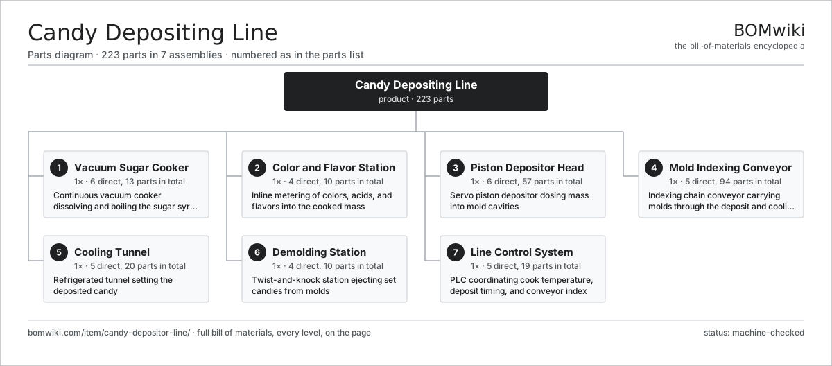
| # | Part | Qty | What it does |
|---|---|---|---|
| 1 | Vacuum Sugar Cooker 6 parts | 1× | Continuous vacuum cooker dissolving and boiling the sugar syrup |
| 2 | Color and Flavor Station 4 parts | 1× | Inline metering of colors, acids, and flavors into the cooked mass |
| 3 | Piston Depositor Head 6 parts | 1× | Servo piston depositor dosing mass into mold cavities |
| 4 | Mold Indexing Conveyor 5 parts | 1× | Indexing chain conveyor carrying molds through the deposit and cooling zones |
| 5 | Cooling Tunnel 5 parts | 1× | Refrigerated tunnel setting the deposited candy |
| 6 | Demolding Station 4 parts | 1× | Twist-and-knock station ejecting set candies from molds |
| 7 | Line Control System 5 parts | 1× | PLC coordinating cook temperature, deposit timing, and conveyor index |
3D model
No 3D model yet. Have a CAD file of this? Add a 3D model — STL renders right on this page; STEP, FreeCAD, and OpenSCAD sources are welcome too (openly licensed, like all 3D models on BOMwiki).
Build & assembly graph
expand / collapse · shared sub-assemblies converge · links to related products · est. labourTap an assembly to expand/collapse · tap a part to open it · use “Open page” for any node · drag to pan, scroll to zoom.
Bill of materials for Candy Depositing Line
7 top-level lines · 56 rows shown · 223 parts total · indented to 3 levels| # | Item / sub-assembly | Part no. | Qty/assy | Ext. qty | Parts | Type |
|---|---|---|---|---|---|---|
| 1 | Vacuum Sugar Cooker 6 parts | candy-depositor-line-sugar-cooker | 1× | 1 | 13 | assembly |
| 1.1 | Dissolving Vessel 3 parts | candy-depositor-line-dissolving-vessel | 1× | 1 | 3 | assembly |
| 1.1.1 | Steam Jacket | candy-depositor-line-vessel-jacket | 1× | 1 | · | part |
| 1.1.2 | Anchor Agitator | candy-depositor-line-agitator | 1× | 1 | · | part |
| 1.1.3 | Water Flow Meter | candy-depositor-line-water-meter | 1× | 1 | · | part |
| 1.2 | Coil Cooker | candy-depositor-line-coil-cooker | 1× | 1 | · | part |
| 1.3 | Vacuum Flash Chamber 3 parts | candy-depositor-line-vacuum-chamber | 1× | 1 | 4 | assembly |
| 1.3.1 | Liquid-Ring Vacuum Pump | candy-depositor-line-vacuum-pump | 1× | 1 | · | part |
| 1.3.2 | Rotary Discharge Valve | candy-depositor-line-discharge-valve | 1× | 1 | · | part |
| 1.3.3 | O-Ring Set | oring-set | 2× | 2 | · | part |
| 1.4 | Syrup Cook Pump | candy-depositor-line-cook-pump | 1× | 1 | · | part |
| 1.5 | Heating Element | heating-element | 2× | 2 | · | part |
| 1.6 | Pressure Sensor | pressure-sensor | 2× | 2 | · | part |
| 2 | Color and Flavor Station 4 parts | candy-depositor-line-color-flavor-station | 1× | 1 | 10 | assembly |
| 2.1 | Peristaltic Dosing Pump | candy-depositor-line-dosing-pump | 4× | 4 | · | part |
| 2.2 | Static Mixer | candy-depositor-line-static-mixer | 1× | 1 | · | part |
| 2.3 | Additive Holding Tank | candy-depositor-line-additive-tank | 4× | 4 | · | part |
| 2.4 | Mass Flow Meter | candy-depositor-line-flow-meter | 1× | 1 | · | part |
| 3 | Piston Depositor Head 6 parts | candy-depositor-line-depositor-head | 1× | 1 | 57 | assembly |
| 3.1 | Piston Manifold Block | candy-depositor-line-piston-block | 1× | 1 | · | part |
| 3.2 | Nozzle Bar | candy-depositor-line-nozzle-bar | 1× | 1 | · | part |
| 3.3 | Servo Actuator | candy-depositor-line-servo-actuator | 2× | 2 | · | part |
| 3.4 | Heated Mass Hopper | candy-depositor-line-hopper | 1× | 1 | · | part |
| 3.5 | Servo Motor 4 parts | servo-motor | 2× | 2 | 24 | assembly |
| 3.5.1 | Stator Assembly 3 parts + deeper › | stator-assembly | 1× | 2 | 3 | assembly |
| 3.5.2 | Rotor Assembly 4 parts + deeper › | rotor-assembly | 1× | 2 | 19 | assembly |
| 3.5.3 | Encoder | encoder | 1× | 2 | · | part |
| 3.5.4 | Motor Housing | motor-housing | 1× | 2 | · | part |
| 3.6 | Heating Element | heating-element | 4× | 4 | · | part |
| 4 | Mold Indexing Conveyor 5 parts | candy-depositor-line-mold-conveyor | 1× | 1 | 94 | assembly |
| 4.1 | Mold Plate | candy-depositor-line-mold-plate | 60× | 60 | · | part |
| 4.2 | Conveyor Chain | candy-depositor-line-conveyor-chain | 1× | 1 | · | part |
| 4.3 | Index Drive Unit | candy-depositor-line-index-drive | 1× | 1 | · | part |
| 4.4 | Ball Bearing | ball-bearing | 8× | 8 | · | part |
| 4.5 | Servo Motor 4 parts | servo-motor | 1× | 1 | 24 | assembly |
| 4.5.1 | Stator Assembly 3 parts + deeper › | stator-assembly | 1× | 1 | 3 | assembly |
| 4.5.2 | Rotor Assembly 4 parts + deeper › | rotor-assembly | 1× | 1 | 19 | assembly |
| 4.5.3 | Encoder | encoder | 1× | 1 | · | part |
| 4.5.4 | Motor Housing | motor-housing | 1× | 1 | · | part |
| 5 | Cooling Tunnel 5 parts | candy-depositor-line-cooling-tunnel | 1× | 1 | 20 | assembly |
| 5.1 | Evaporator Coil | candy-depositor-line-evaporator-coil | 2× | 2 | · | part |
| 5.2 | Tunnel Circulation Fan | candy-depositor-line-tunnel-fan | 4× | 4 | · | part |
| 5.3 | Refrigeration Compressor Unit | candy-depositor-line-refrigeration-unit | 1× | 1 | · | part |
| 5.4 | Insulated Tunnel Panel | candy-depositor-line-tunnel-panel | 12× | 12 | · | part |
| 5.5 | Pressure Sensor | pressure-sensor | 1× | 1 | · | part |
| 6 | Demolding Station 4 parts | candy-depositor-line-demolder | 1× | 1 | 10 | assembly |
| 6.1 | Mold Twist Bar | candy-depositor-line-twist-bar | 1× | 1 | · | part |
| 6.2 | Knockout Tapper | candy-depositor-line-knockout-hammer | 4× | 4 | · | part |
| 6.3 | Discharge Belt | candy-depositor-line-discharge-belt | 1× | 1 | · | part |
| 6.4 | Pneumatic Cylinder | pneumatic-cylinder | 4× | 4 | · | part |
| 7 | Line Control System 5 parts | candy-depositor-line-control-system | 1× | 1 | 19 | assembly |
| 7.1 | Master PLC | candy-depositor-line-plc | 1× | 1 | · | part |
| 7.2 | HMI Touchscreen | candy-depositor-line-hmi | 1× | 1 | · | part |
| 7.3 | Zone Temperature Controller | candy-depositor-line-temp-controller | 4× | 4 | · | part |
| 7.4 | Power Supply | power-supply | 1× | 1 | · | part |
| 7.5 | Relay | relay | 12× | 12 | · | part |
Related products
same domain, ranked by shared parts Fluid Bed Dryer
550 parts · shares 16 with this page
Spray Drying Tower
1,040 parts · shares 16 with this page
Scraped Cooking Kettle
334 parts · shares 13 with this page
Fluid Bed Dryer
550 parts · shares 16 with this page
Spray Drying Tower
1,040 parts · shares 16 with this page
Scraped Cooking Kettle
334 parts · shares 13 with this page
 Paddle Mixer
388 parts · shares 12 with this page
Aseptic Filler
1,020 parts · shares 15 with this page
Paddle Mixer
388 parts · shares 12 with this page
Aseptic Filler
1,020 parts · shares 15 with this page
 Bottle Washing Machine
2,388 parts · shares 15 with this page
Bottle Washing Machine
2,388 parts · shares 15 with this page
Sourcing: possible vendors
Prices, MOQ, and lead times are algorithmic estimates, not quotes, and not claims about these companies. Company mappings are curated by keyword; est. price band $1k–$500k. How estimates work| Vendor | HQ | Specialty | MOQ | Lead time |
|---|---|---|---|---|
| gea.com ↗ | Düsseldorf, DE | Process technology | 20 units | 12–20 wks |
| buhlergroup.com ↗ | Uzwil, CH | Food & materials processing | 20 units | 12–20 wks |
| tetrapak.com ↗ | Pully, CH | Food packaging & processing | 20 units | 12–20 wks |
| jbtc.com ↗ | Chicago, US | Food processing equipment | 20 units | 12–20 wks |
| alfalaval.com ↗ | Lund, SE | Heat transfer & separation | 20 units | 12–20 wks |
993-word article