Juice Deaerator
ProductOverview
A juice deaerator removes dissolved and entrained air from juice before it reaches the filler. Air carried in the product oxidises vitamin C, dulls colour, promotes browning, and causes foaming that throws off fill volumes. The machine works by spraying the juice into a vessel held under vacuum, so the dissolved gas comes out of solution and is drawn away while the deaerated juice collects at the bottom and is pumped on. The whole unit is built on one stainless skid so it drops into a line between the blend tank and the pasteuriser or filler.
The core idea is simple gas physics. The solubility of oxygen and nitrogen in juice falls as pressure drops, so when juice is exposed to a vacuum the excess gas leaves the liquid. Spraying the juice into the Vacuum Vessel turns the feed into many small droplets with a large surface area, which lets the gas escape in the fraction of a second the droplet is in flight. Inlet oxygen of 6-8 ppm is typically brought down to 0.5-1.5 ppm in a single pass.
Vacuum vessel
The Vacuum Vessel is a vertical stainless chamber rated for full vacuum. It is a rolled and welded Vessel Shell closed by a Top Dished Head and a Bottom Conical Head, with the conical bottom feeding the discharge line. A Insulation Jacket insulates the shell so cold juice does not pick up heat or sweat. Two Sight Glass ports and a Manway give access for inspection, and every connection uses a Tri-Clamp Fitting with food-grade gaskets from the O-Ring Set. The vessel stands on three Support Leg supports tied into the skid.
Spray and distribution
Juice enters through the Spray Distribution Head. The Spray Manifold is a ring header feeding six Spray Nozzle units that produce a fine full-cone pattern. A Distribution Plate spreads the flow evenly across the vessel cross-section, and a Spray Baffle keeps the spray off the wall so droplets stay airborne long enough for the gas to release. Nozzle sizing sets the droplet size and therefore the deaeration efficiency, so the nozzles are matched to the rated throughput.
Vacuum generation
The vacuum is made by the Vacuum Generation Unit, built around a Liquid-Ring Vacuum Pump. Inside the pump a Pump Impeller on a Pump Shaft spins a ring of service water inside the Pump Casing, and the moving water acts as a liquid piston that draws and compresses the gas load. The shaft runs on a pair of Ball Bearing units, is sealed by a Mechanical Seal against the Oil Seal set, and breathes through two Port Plate faces. The Vacuum Pump Motor drives the pump, with its Stator Assembly and Rotor Assembly wired through the Motor Terminal Box. Discharged gas and service water pass to the Air/Water Separator, which returns water to the Service Water Tank. A Vacuum Control Valve modulates the actual vacuum, a Non-Return Valve stops backflow, and a Pressure Sensor reports the absolute pressure to the controller through the Vacuum Hose runs.
Pumps and condenser
Two product pumps move juice through the machine. The Feed Pump draws raw juice into the spray head with its Feed Pump Wet End wet end and a Feed Pump Motor on a Pump Base Plate. At the bottom the Discharge Pump pulls deaerated juice out against the vacuum, which is the hard duty in the machine because the pump suction sees low pressure and must avoid cavitation. It uses a Discharge Pump Wet End, a Discharge Pump Motor, and a Magnetic Flow Meter on the outlet so the control loop can match discharge to feed. Vapour and aroma flashed off in the vessel pass to the Vapour Condenser, where a Condenser Tube Bundle inside the Condenser Shell cools the vapour on chilled water. The Condensate Trap collects the liquid and the Vacuum Break Valve admits air to release the vacuum at the end of a run.
Level control and instrumentation
Stable operation depends on the Level Control loop holding juice in a band inside the vessel. A Level Transmitter measures the hydrostatic head, a Level Sight Glass gives a local read, and a Modulating Control Valve with its Pneumatic Actuator trims the inlet flow. A second Pressure Sensor feeds vessel pressure into the calculation so the level reading is compensated for vacuum. If the level falls too far the discharge pump risks running dry, and if it rises too far juice can carry over into the vacuum line, so this loop is tuned tightly.
Control and cleaning
The Control Cabinet houses a PLC with its I/O Card modules and a HMI Touch Panel panel for the operator. Two Variable Frequency Drive drives set feed and discharge pump speed, Motor Starter units handle the fixed-speed loads, and a Power Supply feeds the 24 V control bus inside the Cabinet Enclosure. Between batches the CIP System flushes the wetted path: two CIP Spray Ball heads wash the vessel interior, the CIP Return Pump pulls spent solution back, and CIP Supply Valve units route the cleaning fluids. Everything is carried on the Frame & Skid, a welded Skid Frame on adjustable Leveling Foot supports with the Process Piping Set run as one orbital-welded assembly.
Juice Deaerator parts and their functions
10 top-level parts · 976 parts in total · full bill of materials below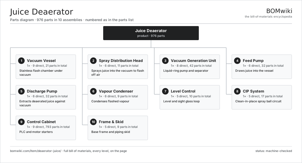
| # | Part | Qty | What it does |
|---|---|---|---|
| 1 | Vacuum Vessel 9 parts | 1× | Stainless flash chamber under vacuum |
| 2 | Spray Distribution Head 6 parts | 1× | Sprays juice into the vacuum to flash off air |
| 3 | Vacuum Generation Unit 8 parts | 1× | Liquid-ring pump and separator |
| 4 | Feed Pump 6 parts | 1× | Draws juice into the vessel |
| 5 | Discharge Pump 6 parts | 1× | Extracts deaerated juice against vacuum |
| 6 | Vapour Condenser 6 parts | 1× | Condenses flashed vapour |
| 7 | Level Control 5 parts | 1× | Level and sight glass loop |
| 8 | CIP System 5 parts | 1× | Clean-in-place spray ball circuit |
| 9 | Control Cabinet 9 parts | 1× | PLC and motor starters |
| 10 | Frame & Skid 5 parts | 1× | Base frame and piping skid |
3D model
No 3D model yet. Have a CAD file of this? Add a 3D model — STL renders right on this page; STEP, FreeCAD, and OpenSCAD sources are welcome too (openly licensed, like all 3D models on BOMwiki).
Build & assembly graph
expand / collapse · shared sub-assemblies converge · links to related products · est. labourTap an assembly to expand/collapse · tap a part to open it · use “Open page” for any node · drag to pan, scroll to zoom.
Bill of materials for Juice Deaerator
10 top-level lines · 123 rows shown · 976 parts total · indented to 3 levels| # | Item / sub-assembly | Part no. | Qty/assy | Ext. qty | Parts | Type |
|---|---|---|---|---|---|---|
| 1 | Vacuum Vessel 9 parts | deaerator-juice-vacuum-vessel | 1× | 1 | 21 | assembly |
| 1.1 | Vessel Shell | deaerator-juice-vessel-shell | 1× | 1 | · | part |
| 1.2 | Top Dished Head | deaerator-juice-dished-head-top | 1× | 1 | · | part |
| 1.3 | Bottom Conical Head | deaerator-juice-dished-head-bottom | 1× | 1 | · | part |
| 1.4 | Insulation Jacket | deaerator-juice-vessel-jacket | 1× | 1 | · | part |
| 1.5 | Sight Glass | deaerator-juice-sight-glass | 2× | 2 | · | part |
| 1.6 | Manway 3 parts | deaerator-juice-vessel-manway | 1× | 1 | 3 | assembly |
| 1.6.1 | Manway Cover | deaerator-juice-manway-cover | 1× | 1 | · | part |
| 1.6.2 | Manway Swing Clamp | deaerator-juice-manway-clamp | 1× | 1 | · | part |
| 1.6.3 | O-Ring Set | oring-set | 1× | 1 | · | part |
| 1.7 | Tri-Clamp Fitting | deaerator-juice-tri-clamp-set | 8× | 8 | · | part |
| 1.8 | O-Ring Set | oring-set | 1× | 1 | · | part |
| 1.9 | Support Leg | deaerator-juice-vessel-leg | 3× | 3 | · | part |
| 2 | Spray Distribution Head 6 parts | deaerator-juice-spray-head | 1× | 1 | 11 | assembly |
| 2.1 | Spray Manifold | deaerator-juice-spray-manifold | 1× | 1 | · | part |
| 2.2 | Spray Nozzle | deaerator-juice-spray-nozzle | 6× | 6 | · | part |
| 2.3 | Distribution Plate | deaerator-juice-distribution-plate | 1× | 1 | · | part |
| 2.4 | Spray Baffle | deaerator-juice-spray-baffle | 1× | 1 | · | part |
| 2.5 | O-Ring Set | oring-set | 1× | 1 | · | part |
| 2.6 | Fastener Set | fastener-set | 1× | 1 | · | part |
| 3 | Vacuum Generation Unit 8 parts | deaerator-juice-vacuum-unit | 1× | 1 | 42 | assembly |
| 3.1 | Liquid-Ring Vacuum Pump 7 parts | deaerator-juice-liquid-ring-pump | 1× | 1 | 10 | assembly |
| 3.1.1 | Pump Casing | deaerator-juice-pump-casing | 1× | 1 | · | part |
| 3.1.2 | Pump Impeller | deaerator-juice-pump-impeller | 1× | 1 | · | part |
| 3.1.3 | Pump Shaft | deaerator-juice-pump-shaft | 1× | 1 | · | part |
| 3.1.4 | Ball Bearing | ball-bearing | 2× | 2 | · | part |
| 3.1.5 | Oil Seal | oil-seal | 2× | 2 | · | part |
| 3.1.6 | Mechanical Seal | deaerator-juice-mechanical-seal | 1× | 1 | · | part |
| 3.1.7 | Port Plate | deaerator-juice-port-plate | 2× | 2 | · | part |
| 3.2 | Vacuum Pump Motor 4 parts | deaerator-juice-vacuum-motor | 1× | 1 | 25 | assembly |
| 3.2.1 | Stator Assembly 3 parts + deeper › | stator-assembly | 1× | 1 | 3 | assembly |
| 3.2.2 | Rotor Assembly 4 parts + deeper › | rotor-assembly | 1× | 1 | 19 | assembly |
| 3.2.3 | Motor Terminal Box | deaerator-juice-motor-terminal-box | 1× | 1 | · | part |
| 3.2.4 | Ball Bearing | ball-bearing | 2× | 2 | · | part |
| 3.3 | Air/Water Separator | deaerator-juice-air-separator | 1× | 1 | · | part |
| 3.4 | Service Water Tank | deaerator-juice-service-water-tank | 1× | 1 | · | part |
| 3.5 | Vacuum Control Valve | deaerator-juice-vacuum-control-valve | 1× | 1 | · | part |
| 3.6 | Non-Return Valve | deaerator-juice-non-return-valve | 1× | 1 | · | part |
| 3.7 | Vacuum Hose | deaerator-juice-vacuum-hose | 2× | 2 | · | part |
| 3.8 | Pressure Sensor | pressure-sensor | 1× | 1 | · | part |
| 4 | Feed Pump 6 parts | deaerator-juice-feed-pump | 1× | 1 | 32 | assembly |
| 4.1 | Feed Pump Wet End 3 parts | deaerator-juice-feed-pump-head | 1× | 1 | 3 | assembly |
| 4.1.1 | Feed Pump Casing | deaerator-juice-feed-casing | 1× | 1 | · | part |
| 4.1.2 | Feed Pump Impeller | deaerator-juice-feed-impeller | 1× | 1 | · | part |
| 4.1.3 | O-Ring Set | oring-set | 1× | 1 | · | part |
| 4.2 | Feed Pump Motor 3 parts | deaerator-juice-feed-pump-motor | 1× | 1 | 24 | assembly |
| 4.2.1 | Stator Assembly 3 parts + deeper › | stator-assembly | 1× | 1 | 3 | assembly |
| 4.2.2 | Rotor Assembly 4 parts + deeper › | rotor-assembly | 1× | 1 | 19 | assembly |
| 4.2.3 | Ball Bearing | ball-bearing | 2× | 2 | · | part |
| 4.3 | Mechanical Seal | deaerator-juice-mechanical-seal | 1× | 1 | · | part |
| 4.4 | Ball Bearing | ball-bearing | 2× | 2 | · | part |
| 4.5 | Pump Base Plate | deaerator-juice-pump-base | 1× | 1 | · | part |
| 4.6 | Fastener Set | fastener-set | 1× | 1 | · | part |
| 5 | Discharge Pump 6 parts | deaerator-juice-discharge-pump | 1× | 1 | 32 | assembly |
| 5.1 | Discharge Pump Wet End 3 parts | deaerator-juice-discharge-pump-head | 1× | 1 | 3 | assembly |
| 5.1.1 | Discharge Pump Casing | deaerator-juice-discharge-casing | 1× | 1 | · | part |
| 5.1.2 | Discharge Pump Impeller | deaerator-juice-discharge-impeller | 1× | 1 | · | part |
| 5.1.3 | O-Ring Set | oring-set | 1× | 1 | · | part |
| 5.2 | Discharge Pump Motor 3 parts | deaerator-juice-discharge-pump-motor | 1× | 1 | 24 | assembly |
| 5.2.1 | Stator Assembly 3 parts + deeper › | stator-assembly | 1× | 1 | 3 | assembly |
| 5.2.2 | Rotor Assembly 4 parts + deeper › | rotor-assembly | 1× | 1 | 19 | assembly |
| 5.2.3 | Ball Bearing | ball-bearing | 2× | 2 | · | part |
| 5.3 | Mechanical Seal | deaerator-juice-mechanical-seal | 1× | 1 | · | part |
| 5.4 | Ball Bearing | ball-bearing | 2× | 2 | · | part |
| 5.5 | Pump Base Plate | deaerator-juice-pump-base | 1× | 1 | · | part |
| 5.6 | Magnetic Flow Meter | deaerator-juice-flow-meter | 1× | 1 | · | part |
| 6 | Vapour Condenser 6 parts | deaerator-juice-condenser | 1× | 1 | 9 | assembly |
| 6.1 | Condenser Shell | deaerator-juice-condenser-shell | 1× | 1 | · | part |
| 6.2 | Condenser Tube Bundle | deaerator-juice-condenser-tube-bundle | 1× | 1 | · | part |
| 6.3 | Condensate Trap | deaerator-juice-condensate-trap | 1× | 1 | · | part |
| 6.4 | Vacuum Break Valve | deaerator-juice-vacuum-break-valve | 1× | 1 | · | part |
| 6.5 | O-Ring Set | oring-set | 1× | 1 | · | part |
| 6.6 | Tri-Clamp Fitting | deaerator-juice-tri-clamp-set | 4× | 4 | · | part |
| 7 | Level Control 5 parts | deaerator-juice-level-control | 1× | 1 | 10 | assembly |
| 7.1 | Level Transmitter | deaerator-juice-level-transmitter | 1× | 1 | · | part |
| 7.2 | Level Sight Glass | deaerator-juice-level-sight-glass | 1× | 1 | · | part |
| 7.3 | Modulating Control Valve 3 parts | deaerator-juice-modulating-valve | 1× | 1 | 3 | assembly |
| 7.3.1 | Valve Body | deaerator-juice-valve-body | 1× | 1 | · | part |
| 7.3.2 | Pneumatic Actuator | deaerator-juice-valve-actuator | 1× | 1 | · | part |
| 7.3.3 | O-Ring Set | oring-set | 1× | 1 | · | part |
| 7.4 | Pressure Sensor | pressure-sensor | 1× | 1 | · | part |
| 7.5 | Connector | connector | 4× | 4 | · | part |
| 8 | CIP System 5 parts | deaerator-juice-cip-system | 1× | 1 | 17 | assembly |
| 8.1 | CIP Spray Ball | deaerator-juice-cip-spray-ball | 2× | 2 | · | part |
| 8.2 | CIP Return Pump 4 parts | deaerator-juice-cip-return-pump | 1× | 1 | 5 | assembly |
| 8.2.1 | Feed Pump Casing | deaerator-juice-feed-casing | 1× | 1 | · | part |
| 8.2.2 | Feed Pump Impeller | deaerator-juice-feed-impeller | 1× | 1 | · | part |
| 8.2.3 | Mechanical Seal | deaerator-juice-mechanical-seal | 1× | 1 | · | part |
| 8.2.4 | Ball Bearing | ball-bearing | 2× | 2 | · | part |
| 8.3 | CIP Supply Valve | deaerator-juice-cip-supply-valve | 2× | 2 | · | part |
| 8.4 | CIP Hose | deaerator-juice-cip-hose | 2× | 2 | · | part |
| 8.5 | Tri-Clamp Fitting | deaerator-juice-tri-clamp-set | 6× | 6 | · | part |
| 9 | Control Cabinet 9 parts | deaerator-juice-control-cabinet | 1× | 1 | 793 | assembly |
| 9.1 | PLC 4 parts | deaerator-juice-plc | 1× | 1 | 446 | assembly |
| 9.1.1 | Bare PCB | pcb-bare | 1× | 1 | · | part |
| 9.1.2 | Microcontroller | mcu | 1× | 1 | · | part |
| 9.1.3 | I/O Card 4 parts + deeper › | deaerator-juice-io-card | 4× | 4 | 81 | assembly |
| 9.1.4 | SMD Passive (R/C/L) | smd-passives | 120× | 120 | · | part |
| 9.2 | HMI Touch Panel 4 parts | deaerator-juice-hmi-touch | 1× | 1 | 83 | assembly |
| 9.2.1 | Bare PCB | pcb-bare | 1× | 1 | · | part |
| 9.2.2 | Microcontroller | mcu | 1× | 1 | · | part |
| 9.2.3 | LCD Panel | lcd-panel | 1× | 1 | · | part |
| 9.2.4 | SMD Passive (R/C/L) | smd-passives | 80× | 80 | · | part |
| 9.3 | Variable Frequency Drive 4 parts | deaerator-juice-vfd | 2× | 2 | 108 | assembly |
| 9.3.1 | Bare PCB | pcb-bare | 1× | 2 | · | part |
| 9.3.2 | Power MOSFET | mosfet | 6× | 12 | · | part |
| 9.3.3 | Power Supply | power-supply | 1× | 2 | · | part |
| 9.3.4 | SMD Passive (R/C/L) | smd-passives | 100× | 200 | · | part |
| 9.4 | Motor Starter | deaerator-juice-motor-starter | 2× | 2 | · | part |
| 9.5 | Power Supply | power-supply | 1× | 1 | · | part |
| 9.6 | Relay | relay | 8× | 8 | · | part |
| 9.7 | Cabinet Enclosure 3 parts | deaerator-juice-cabinet-enclosure | 1× | 1 | 6 | assembly |
| 9.7.1 | Sheet Metal Panel | sheet-panel | 4× | 4 | · | part |
| 9.7.2 | Cabinet Door | deaerator-juice-cabinet-door | 1× | 1 | · | part |
| 9.7.3 | Fastener Set | fastener-set | 1× | 1 | · | part |
| 9.8 | Wire Bundle | wire-bundle | 1× | 1 | · | part |
| 9.9 | Connector | connector | 30× | 30 | · | part |
| 10 | Frame & Skid 5 parts | deaerator-juice-frame-skid | 1× | 1 | 9 | assembly |
| 10.1 | Skid Frame | deaerator-juice-skid-frame | 1× | 1 | · | part |
| 10.2 | Leveling Foot | deaerator-juice-leveling-foot | 4× | 4 | · | part |
| 10.3 | Process Piping Set | deaerator-juice-process-piping | 1× | 1 | · | part |
| 10.4 | Guard Panel | deaerator-juice-guard-panel | 2× | 2 | · | part |
| 10.5 | Fastener Set | fastener-set | 1× | 1 | · | part |
Related products
same domain, ranked by shared parts Juice Extraction Line
399 parts · shares 20 with this page
Fruit Grading Line
3,765 parts · shares 19 with this page
Juice Extraction Line
399 parts · shares 20 with this page
Fruit Grading Line
3,765 parts · shares 19 with this page
 Grain Color Sorter
3,056 parts · shares 18 with this page
Grain Color Sorter
3,056 parts · shares 18 with this page
 High-Pressure Homogenizer
533 parts · shares 18 with this page
Confectionery Depositor
699 parts · shares 17 with this page
High-Pressure Homogenizer
533 parts · shares 18 with this page
Confectionery Depositor
699 parts · shares 17 with this page
 Conveyor Pizza Oven
176 parts · shares 14 with this page
Conveyor Pizza Oven
176 parts · shares 14 with this page
Sourcing: possible vendors
Prices, MOQ, and lead times are algorithmic estimates, not quotes, and not claims about these companies. Company mappings are curated by keyword; est. price band $1k–$500k. How estimates work| Vendor | HQ | Specialty | MOQ | Lead time |
|---|---|---|---|---|
| gea.com ↗ | Düsseldorf, DE | Process technology | 20 units | 12–20 wks |
| buhlergroup.com ↗ | Uzwil, CH | Food & materials processing | 20 units | 12–20 wks |
| tetrapak.com ↗ | Pully, CH | Food packaging & processing | 20 units | 12–20 wks |
| jbtc.com ↗ | Chicago, US | Food processing equipment | 20 units | 12–20 wks |
| alfalaval.com ↗ | Lund, SE | Heat transfer & separation | 20 units | 12–20 wks |
990-word article