Tubular Sterilizer
ProductOverview
A tubular sterilizer is a continuous ultra-high-temperature (UHT) skid that sterilizes liquid and viscous food by pumping it through heated tubes rather than holding it in batches. It suits products that foul or damage plate heat exchangers: tomato concentrate, fruit purees, custards, soups, sauces, dairy desserts, and products carrying fibres or small particulates. The product never contacts the heating medium. Heat passes through the wall of a Heating Inner Tube from hot water on the outer shell into the product flowing inside. Because flow is continuous and the geometry is simple, the machine cleans in place and runs for long production cycles between strip-downs.
The skid is built as a sequence of tubular heat exchanger banks: a preheating bank, a heating bank, a Holding Tube, and a cooling bank. Product is metered through all of them by a single positive-displacement Feed and Timing Pump whose speed fixes the residence time in the holding tube. A Control Panel holds the heating, holding, and diversion logic and writes the legal time-temperature record that the process authority files for each run.
How the UHT cycle works
Cold product enters the Feed and Timing Pump, a timing pump that delivers a fixed volume per revolution. Fixing the flow fixes how long each element of product spends in the holding tube, which is the legal basis of the sterilization. From the pump the product enters the Preheating Bank, where it is warmed to 70 to 90 C by heat recovered from the outgoing sterilized product. This regeneration cuts steam and cooling water demand by 60 to 90 percent.
The preheated product passes into the Heating and Sterilizing Bank, where the indirect hot water loop raises it to the sterilization temperature of 135 to 150 C in a few seconds. It then enters the holding tube, an insulated run of fixed length sized so that at rated flow the product stays at temperature for the required 2 to 6 seconds. This short hold at high temperature destroys spores while limiting cooking of flavour and colour. The product then gives up its heat in the Preheating Bank regeneration loop and the Cooling Bank, leaving at 20 to 30 C for aseptic filling or storage in the Aseptic Surge Tank.
Tubular exchanger construction
Each bank is a set of concentric or multi-tube assemblies. In a tube-in-tube design a single product tube runs inside a larger shell tube; in a multi-tube design several product tubes sit inside one shell. The product flows through the Heating Inner Tube while hot water or cooling water flows through the Heating Outer Shell in counterflow. Tube ends are held in tube sheets that separate the product and service streams. Passes are linked by U-bends so the product follows a long serpentine path within a compact frame.
Because the heating and cooling banks swing across more than 100 C, the steel grows and shrinks measurably. Each bank carries Expansion Bellows that absorb this movement so the tube sheets and welds are not overstressed. Support brackets carry the bank weight and let the tubes float. All product surfaces are 316L stainless steel with a polished bore, since viscous foods burn onto rough walls and resist cleaning.
Heating and holding
Steam is not injected into the product. The Steam and Hot Water Heating Set uses a steam injector and modulating control valve to keep a closed hot water loop at 5 to 10 C above the product target, and a circulation pump drives that water through the heating shell. This indirect arrangement gives a gentle, controllable wall temperature and avoids local scorching. The holding tube is insulated so the product enters and leaves at almost the same temperature; the small loss along its length is accounted for in sizing. A Temperature Sensor at the holding tube outlet is the controlling measurement for the whole sterilization.
Cooling and back-pressure
After the hold, the product is cooled first by regeneration and then by the Cooling Water Set cooling water circuit. Throughout the high-temperature zone the product is well above its atmospheric boiling point, so it must be kept under pressure to stay liquid. A Back-Pressure Valve maintains 10 to 16 bar on the product side; without it the product would flash to steam in the tubes. A Pressure Sensor confirms the back-pressure is held. If the holding tube outlet ever falls below the sterilization setpoint, the Flow-Diversion Valve routes that product to drain instead of to the filler, so under-processed product cannot reach packaging.
Materials and sanitation
Every product contact surface is 316L stainless with sanitary clamp connections and food-grade seals from the CIP and Sanitary Connection Set. The skid cleans in place: cleaning solution circulates through the same tubes and valves at controlled temperature and flow, removing fouling without opening the circuit. The Aseptic Surge Tank holds positive pressure behind a sterile air filter so no airborne contamination reaches sterilized product. Seals throughout use the O-Ring Set and gasket parts rated for repeated thermal and chemical cycling.
Variants and use
Tube-in-tube units handle the most viscous and particulate products because a single wide bore resists clogging, while multi-tube units give more heat transfer area per unit length for thinner products at higher throughput. Capacity scales by adding tube length and parallel passes rather than redesigning the machine. Tubular sterilizers are chosen over plate sterilizers wherever the product is viscous, carries fibres or particles, or fouls badly, accepting a larger footprint and higher pumping pressure in exchange for longer runs between cleaning.
Tubular Sterilizer parts and their functions
12 top-level parts · 221 parts in total · full bill of materials below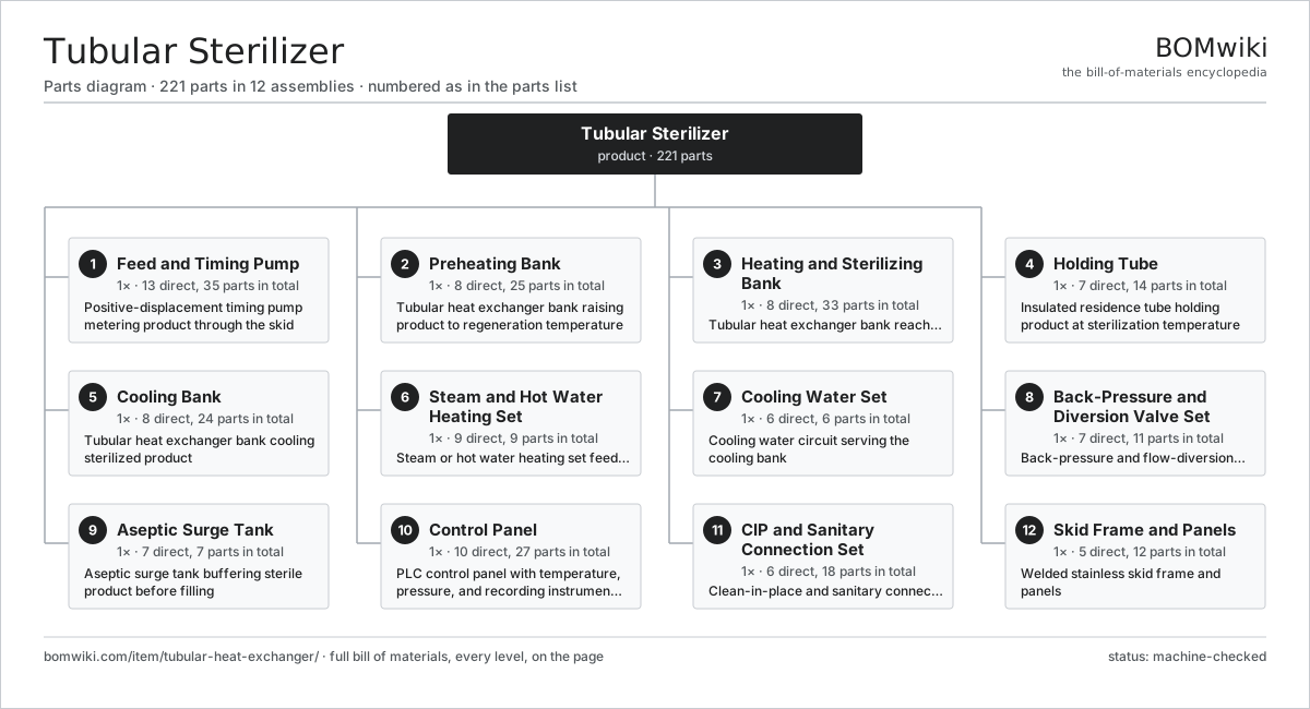
| # | Part | Qty | What it does |
|---|---|---|---|
| 1 | Feed and Timing Pump 13 parts | 1× | Positive-displacement timing pump metering product through the skid |
| 2 | Preheating Bank 8 parts | 1× | Tubular heat exchanger bank raising product to regeneration temperature |
| 3 | Heating and Sterilizing Bank 8 parts | 1× | Tubular heat exchanger bank reaching sterilization temperature |
| 4 | Holding Tube 7 parts | 1× | Insulated residence tube holding product at sterilization temperature |
| 5 | Cooling Bank 8 parts | 1× | Tubular heat exchanger bank cooling sterilized product |
| 6 | Steam and Hot Water Heating Set 9 parts | 1× | Steam or hot water heating set feeding the heating bank |
| 7 | Cooling Water Set 6 parts | 1× | Cooling water circuit serving the cooling bank |
| 8 | Back-Pressure and Diversion Valve Set 7 parts | 1× | Back-pressure and flow-diversion valves controlling sterile flow |
| 9 | Aseptic Surge Tank 7 parts | 1× | Aseptic surge tank buffering sterile product before filling |
| 10 | Control Panel 10 parts | 1× | PLC control panel with temperature, pressure, and recording instruments |
| 11 | CIP and Sanitary Connection Set 6 parts | 1× | Clean-in-place and sanitary connection set |
| 12 | Skid Frame and Panels 5 parts | 1× | Welded stainless skid frame and panels |
3D model
No 3D model yet. Have a CAD file of this? Add a 3D model — STL renders right on this page; STEP, FreeCAD, and OpenSCAD sources are welcome too (openly licensed, like all 3D models on BOMwiki).
Build & assembly graph
expand / collapse · shared sub-assemblies converge · links to related products · est. labourTap an assembly to expand/collapse · tap a part to open it · use “Open page” for any node · drag to pan, scroll to zoom.
Bill of materials for Tubular Sterilizer
12 top-level lines · 118 rows shown · 221 parts total · indented to 3 levels| # | Item / sub-assembly | Part no. | Qty/assy | Ext. qty | Parts | Type |
|---|---|---|---|---|---|---|
| 1 | Feed and Timing Pump 13 parts | tubular-heat-exchanger-feed-pump | 1× | 1 | 35 | assembly |
| 1.1 | Pump Casing | tubular-heat-exchanger-pump-casing | 1× | 1 | · | part |
| 1.2 | Stator Assembly 3 parts | stator-assembly | 1× | 1 | 3 | assembly |
| 1.2.1 | Stator Core (laminations) | stator-core | 1× | 1 | · | part |
| 1.2.2 | Copper Winding | copper-winding | 1× | 1 | · | part |
| 1.2.3 | Slot Insulation | stator-insulation | 1× | 1 | · | part |
| 1.3 | Rotor Assembly 4 parts | rotor-assembly | 1× | 1 | 19 | assembly |
| 1.3.1 | Rotor Shaft | rotor-shaft | 1× | 1 | · | part |
| 1.3.2 | Rotor Core | rotor-core | 1× | 1 | · | part |
| 1.3.3 | Neodymium Magnet | neodymium-magnet | 16× | 16 | · | part |
| 1.3.4 | Ball Bearing | ball-bearing | 1× | 1 | · | part |
| 1.4 | Pump Drive Motor | tubular-heat-exchanger-pump-motor | 1× | 1 | · | part |
| 1.5 | Helical Gear Pair | gear-pair | 1× | 1 | · | part |
| 1.6 | Gearbox Housing | gearbox-housing | 1× | 1 | · | part |
| 1.7 | Drive Belt | drive-belt | 1× | 1 | · | part |
| 1.8 | Pump Drive Shaft | tubular-heat-exchanger-pump-shaft | 1× | 1 | · | part |
| 1.9 | Ball Bearing | ball-bearing | 2× | 2 | · | part |
| 1.10 | Oil Seal | oil-seal | 2× | 2 | · | part |
| 1.11 | Pump Mechanical Seal | tubular-heat-exchanger-pump-mech-seal | 1× | 1 | · | part |
| 1.12 | O-Ring Set | oring-set | 1× | 1 | · | part |
| 1.13 | Fastener Set | fastener-set | 1× | 1 | · | part |
| 2 | Preheating Bank 8 parts | tubular-heat-exchanger-preheat-bank | 1× | 1 | 25 | assembly |
| 2.1 | Preheat Inner Tube | tubular-heat-exchanger-preheat-inner-tube | 6× | 6 | · | part |
| 2.2 | Preheat Outer Shell | tubular-heat-exchanger-preheat-outer-shell | 3× | 3 | · | part |
| 2.3 | Preheat Tube Sheet | tubular-heat-exchanger-preheat-tube-sheet | 4× | 4 | · | part |
| 2.4 | Preheat U-Bend | tubular-heat-exchanger-preheat-ubend | 4× | 4 | · | part |
| 2.5 | Expansion Bellows | tubular-heat-exchanger-expansion-bellows | 2× | 2 | · | part |
| 2.6 | Support Bracket | tubular-heat-exchanger-support-bracket | 4× | 4 | · | part |
| 2.7 | O-Ring Set | oring-set | 1× | 1 | · | part |
| 2.8 | Fastener Set | fastener-set | 1× | 1 | · | part |
| 3 | Heating and Sterilizing Bank 8 parts | tubular-heat-exchanger-heating-bank | 1× | 1 | 33 | assembly |
| 3.1 | Heating Inner Tube | tubular-heat-exchanger-heating-inner-tube | 8× | 8 | · | part |
| 3.2 | Heating Outer Shell | tubular-heat-exchanger-heating-outer-shell | 4× | 4 | · | part |
| 3.3 | Heating Tube Sheet | tubular-heat-exchanger-heating-tube-sheet | 6× | 6 | · | part |
| 3.4 | Heating U-Bend | tubular-heat-exchanger-heating-ubend | 6× | 6 | · | part |
| 3.5 | Expansion Bellows | tubular-heat-exchanger-expansion-bellows | 3× | 3 | · | part |
| 3.6 | Support Bracket | tubular-heat-exchanger-support-bracket | 4× | 4 | · | part |
| 3.7 | O-Ring Set | oring-set | 1× | 1 | · | part |
| 3.8 | Fastener Set | fastener-set | 1× | 1 | · | part |
| 4 | Holding Tube 7 parts | tubular-heat-exchanger-holding-tube | 1× | 1 | 14 | assembly |
| 4.1 | Holding Tube Section | tubular-heat-exchanger-holding-tube-section | 4× | 4 | · | part |
| 4.2 | Holding Tube Bend | tubular-heat-exchanger-holding-tube-bend | 3× | 3 | · | part |
| 4.3 | Holding Tube Insulation | tubular-heat-exchanger-holding-tube-insulation | 1× | 1 | · | part |
| 4.4 | Support Bracket | tubular-heat-exchanger-support-bracket | 3× | 3 | · | part |
| 4.5 | Pressure Sensor | pressure-sensor | 1× | 1 | · | part |
| 4.6 | O-Ring Set | oring-set | 1× | 1 | · | part |
| 4.7 | Fastener Set | fastener-set | 1× | 1 | · | part |
| 5 | Cooling Bank 8 parts | tubular-heat-exchanger-cooling-bank | 1× | 1 | 24 | assembly |
| 5.1 | Cooling Inner Tube | tubular-heat-exchanger-cooling-inner-tube | 6× | 6 | · | part |
| 5.2 | Cooling Outer Shell | tubular-heat-exchanger-cooling-outer-shell | 3× | 3 | · | part |
| 5.3 | Cooling Tube Sheet | tubular-heat-exchanger-cooling-tube-sheet | 4× | 4 | · | part |
| 5.4 | Cooling U-Bend | tubular-heat-exchanger-cooling-ubend | 4× | 4 | · | part |
| 5.5 | Expansion Bellows | tubular-heat-exchanger-expansion-bellows | 2× | 2 | · | part |
| 5.6 | Support Bracket | tubular-heat-exchanger-support-bracket | 3× | 3 | · | part |
| 5.7 | O-Ring Set | oring-set | 1× | 1 | · | part |
| 5.8 | Fastener Set | fastener-set | 1× | 1 | · | part |
| 6 | Steam and Hot Water Heating Set 9 parts | tubular-heat-exchanger-steam-set | 1× | 1 | 9 | assembly |
| 6.1 | Steam Injector | tubular-heat-exchanger-steam-injector | 1× | 1 | · | part |
| 6.2 | Heating Element | heating-element | 1× | 1 | · | part |
| 6.3 | Steam Control Valve | tubular-heat-exchanger-steam-control-valve | 1× | 1 | · | part |
| 6.4 | Hot Water Circulation Pump | tubular-heat-exchanger-hotwater-pump | 1× | 1 | · | part |
| 6.5 | Steam Trap | tubular-heat-exchanger-steam-trap | 1× | 1 | · | part |
| 6.6 | Steam Strainer | tubular-heat-exchanger-steam-strainer | 1× | 1 | · | part |
| 6.7 | Pressure Sensor | pressure-sensor | 1× | 1 | · | part |
| 6.8 | O-Ring Set | oring-set | 1× | 1 | · | part |
| 6.9 | Fastener Set | fastener-set | 1× | 1 | · | part |
| 7 | Cooling Water Set 6 parts | tubular-heat-exchanger-cooling-set | 1× | 1 | 6 | assembly |
| 7.1 | Cooling Water Pump | tubular-heat-exchanger-cooling-pump | 1× | 1 | · | part |
| 7.2 | Cooling Control Valve | tubular-heat-exchanger-cooling-control-valve | 1× | 1 | · | part |
| 7.3 | Cooling Water Strainer | tubular-heat-exchanger-cooling-strainer | 1× | 1 | · | part |
| 7.4 | Pressure Sensor | pressure-sensor | 1× | 1 | · | part |
| 7.5 | O-Ring Set | oring-set | 1× | 1 | · | part |
| 7.6 | Fastener Set | fastener-set | 1× | 1 | · | part |
| 8 | Back-Pressure and Diversion Valve Set 7 parts | tubular-heat-exchanger-valve-set | 1× | 1 | 11 | assembly |
| 8.1 | Back-Pressure Valve | tubular-heat-exchanger-backpressure-valve | 1× | 1 | · | part |
| 8.2 | Flow-Diversion Valve | tubular-heat-exchanger-diversion-valve | 1× | 1 | · | part |
| 8.3 | Aseptic Block Valve | tubular-heat-exchanger-sterile-block-valve | 2× | 2 | · | part |
| 8.4 | Valve Actuator | tubular-heat-exchanger-valve-actuator | 3× | 3 | · | part |
| 8.5 | Pressure Sensor | pressure-sensor | 2× | 2 | · | part |
| 8.6 | O-Ring Set | oring-set | 1× | 1 | · | part |
| 8.7 | Fastener Set | fastener-set | 1× | 1 | · | part |
| 9 | Aseptic Surge Tank 7 parts | tubular-heat-exchanger-surge-tank | 1× | 1 | 7 | assembly |
| 9.1 | Surge Vessel | tubular-heat-exchanger-surge-vessel | 1× | 1 | · | part |
| 9.2 | Sterile Air Filter | tubular-heat-exchanger-sterile-air-filter | 1× | 1 | · | part |
| 9.3 | Level Probe | tubular-heat-exchanger-level-probe | 1× | 1 | · | part |
| 9.4 | CIP Spray Ball | tubular-heat-exchanger-surge-spray-ball | 1× | 1 | · | part |
| 9.5 | Pressure Sensor | pressure-sensor | 1× | 1 | · | part |
| 9.6 | O-Ring Set | oring-set | 1× | 1 | · | part |
| 9.7 | Fastener Set | fastener-set | 1× | 1 | · | part |
| 10 | Control Panel 10 parts | tubular-heat-exchanger-control-panel | 1× | 1 | 27 | assembly |
| 10.1 | Programmable Logic Controller | tubular-heat-exchanger-plc | 1× | 1 | · | part |
| 10.2 | Temperature Sensor | tubular-heat-exchanger-temp-sensor | 4× | 4 | · | part |
| 10.3 | Pressure Sensor | pressure-sensor | 2× | 2 | · | part |
| 10.4 | Chart Recorder | tubular-heat-exchanger-chart-recorder | 1× | 1 | · | part |
| 10.5 | Relay | relay | 6× | 6 | · | part |
| 10.6 | Power Supply | power-supply | 1× | 1 | · | part |
| 10.7 | LCD Panel | lcd-panel | 1× | 1 | · | part |
| 10.8 | Control I/O Board 5 parts | tubular-heat-exchanger-control-pcb | 1× | 1 | 9 | assembly |
| 10.8.1 | Bare PCB | pcb-bare | 1× | 1 | · | part |
| 10.8.2 | Microcontroller | mcu | 1× | 1 | · | part |
| 10.8.3 | SMD Passive (R/C/L) | smd-passives | 1× | 1 | · | part |
| 10.8.4 | Connector | connector | 4× | 4 | · | part |
| 10.8.5 | Relay | relay | 2× | 2 | · | part |
| 10.9 | Wire Bundle | wire-bundle | 1× | 1 | · | part |
| 10.10 | Fastener Set | fastener-set | 1× | 1 | · | part |
| 11 | CIP and Sanitary Connection Set 6 parts | tubular-heat-exchanger-cip-set | 1× | 1 | 18 | assembly |
| 11.1 | CIP Changeover Valve | tubular-heat-exchanger-cip-valve | 2× | 2 | · | part |
| 11.2 | CIP Return Pump | tubular-heat-exchanger-cip-return-pump | 1× | 1 | · | part |
| 11.3 | Tri-Clamp Connection | tubular-heat-exchanger-tri-clamp | 12× | 12 | · | part |
| 11.4 | Sanitary Gasket Set | tubular-heat-exchanger-gasket-set | 1× | 1 | · | part |
| 11.5 | O-Ring Set | oring-set | 1× | 1 | · | part |
| 11.6 | Fastener Set | fastener-set | 1× | 1 | · | part |
| 12 | Skid Frame and Panels 5 parts | tubular-heat-exchanger-frame | 1× | 1 | 12 | assembly |
| 12.1 | Frame Rail | tubular-heat-exchanger-frame-rail | 1× | 1 | · | part |
| 12.2 | Sheet Metal Panel | sheet-panel | 4× | 4 | · | part |
| 12.3 | Access Panel | tubular-heat-exchanger-access-panel | 2× | 2 | · | part |
| 12.4 | Leveling Foot | tubular-heat-exchanger-leveling-foot | 4× | 4 | · | part |
| 12.5 | Fastener Set | fastener-set | 1× | 1 | · | part |
Related products
same domain, ranked by shared parts Edible Oil Refining Line
3,224 parts · shares 23 with this page
Egg Breaking and Separating Line
1,126 parts · shares 23 with this page
Edible Oil Refining Line
3,224 parts · shares 23 with this page
Egg Breaking and Separating Line
1,126 parts · shares 23 with this page
 Juice Extraction Line
399 parts · shares 23 with this page
UHT Processing System
1,033 parts · shares 23 with this page
Juice Extraction Line
399 parts · shares 23 with this page
UHT Processing System
1,033 parts · shares 23 with this page
 Bottle Washing Machine
2,388 parts · shares 22 with this page
Yogurt Production Line
271 parts · shares 22 with this page
Bottle Washing Machine
2,388 parts · shares 22 with this page
Yogurt Production Line
271 parts · shares 22 with this page
Sourcing: possible vendors
Prices, MOQ, and lead times are algorithmic estimates, not quotes, and not claims about these companies. Company mappings are curated by keyword; est. price band $1k–$500k. How estimates work| Vendor | HQ | Specialty | MOQ | Lead time |
|---|---|---|---|---|
| gea.com ↗ | Düsseldorf, DE | Process technology | 20 units | 12–20 wks |
| buhlergroup.com ↗ | Uzwil, CH | Food & materials processing | 20 units | 12–20 wks |
| tetrapak.com ↗ | Pully, CH | Food packaging & processing | 20 units | 12–20 wks |
| jbtc.com ↗ | Chicago, US | Food processing equipment | 20 units | 12–20 wks |
| alfalaval.com ↗ | Lund, SE | Heat transfer & separation | 20 units | 12–20 wks |
977-word article