UHT Processing System
ProductOverview
The UHT Processing System takes raw liquid food, holds it at ultra-high temperature for a few seconds, then cools and back-pressures it for aseptic filling. A complete run moves product from the Balance Tank Assembly through the Pump Skid, up the Heat Exchanger Train, through the Holding Tube Assembly, and back down the same train for cooling before it passes the Aseptic Valve Cluster. The line is sized for 5,000 L/h and holds product at 137-142 C for 4 seconds, which inactivates spores while limiting the cooked flavor that longer hold times produce. Every wetted part is AISI 316L with a polished finish below 0.8 micron so that protein and mineral deposits do not anchor to the surface.
The system is an indirect design. Product never touches steam. The final heating energy comes from a closed pressurized water loop that is itself heated by steam, so the sterile product side is isolated from the utility side by a wall of stainless plate. This trades a small drop in heat transfer for a clean separation between the food and the boiler water.
Feed and Pressure
The Balance Tank Assembly is a 200 L vessel that holds a constant liquid level through the Float Valve, so the Feed Pump always sees the same suction head. Two Level Probe rods raise low and high alarms, and a 0.2 micron Sterile Vent Filter keeps the headspace sterile while the level moves. The Feed Pump is a sanitary centrifugal unit built around a cast Pump Casing and an open Pump Impeller, sealed by a single Mechanical Seal.
Flow rate sets holding time, so the rate is fixed by a positive-displacement Timing Pump. Its tri-lobe Lobe Rotor pair is kept in phase by a Helical Gear Pair inside the Gearbox Housing, and the Oil Seal barrier between gearbox and product stops lubricant migration. The Aseptic Booster Pump raises pressure on the regeneration side above the hot product side. If a plate develops a pinhole, the higher-pressure raw side leaks into the sterile side rather than the reverse, which protects the finished product. Each pump runs from a Variable-Frequency Drive.
Heat Exchanger Train
The Heat Exchanger Train is one plate frame split into four duties. The Regeneration Section recovers heat from outgoing sterile product to preheat incoming feed and reaches around 90 percent regeneration, which is where most of the energy economy comes from. The Preheat Section lifts feed toward 80 C, the Final Heating Section drives it to sterilization temperature against the hot-water loop, and the Cooling Section drops the sterile product to fill temperature using the cooling loop. Each section is a stack of pressed Heat Transfer Plate units separated by clip-on Plate Gasket seals.
The four stacks share one PHE Frame. A Frame Plate anchors the ports, a movable Pressure Plate rides on the Carry Bar, and eight Tie Bolt units compress the pack to its rated plate gap. Compression has to be exact: too loose and the gaskets weep, too tight and the plates deform.
Holding and Homogenizing
The Holding Tube Assembly is the legal heart of the process. Its Holding Coil is sized so that the fastest particle of product still spends the full hold time above sterilization temperature. The Tube Insulation Jacket limits heat loss along the loop, and an Inlet RTD with an Outlet RTD bracket the tube so the controller knows the true hold temperature at both ends.
The Homogenizer sits in the preheat zone and breaks fat globules to a stable size. Three ceramic Ceramic Plunger units run in the forged Pump Block, pushing product through the First-Stage Valve at 200 bar and then the Second-Stage Valve at 50 bar. The plungers are driven from the Crankcase through a Helical Gear Pair and a Drive Belt set, with the crankshaft carried on a Ball Bearing string.
Heating and Cooling Loops
The Hot-Water Heating Loop is a closed water circuit. A Steam Injector adds culinary steam to the circulating water, the Hot-Water Pump keeps it moving through the final heating section, and a Expansion Vessel absorbs thermal growth. A Steam Control Valve modulates the heat input against the outlet RTD, and two Steam Trap units drain condensate. The Cooling Loop mirrors it on the cold side: a packaged Glycol Chiller built around a Scroll Compressor and a Brazed-Plate Evaporator makes 2 C glycol that the Chilled-Water Pump sends through the cooling section, buffered by the Glycol Buffer Tank.
Valves, Cleaning and Control
On the sterile side the Aseptic Valve Cluster decides where product goes. The Flow-Diversion Valve dumps any under-temperature product to drain, and the Back-Pressure Valve holds the whole hot section above the boiling point so product cannot flash to steam. Six Aseptic Valve units with steam barriers isolate the sterile path, each driven by a Pneumatic Actuator, and a Magnetic Flow Meter confirms the rate.
Between runs the CIP / SIP Circuit cleans the whole product path. The CIP Pump pushes caustic then acid from two CIP Tank vessels through a CIP Heater fitted with Heating Element rods, with a Conductivity Sensor tracking phase changes in the return. The whole sequence runs from the Control System, where a SIL 2 Safety PLC reads distributed I/O Module units, presents the run on the HMI Panel, and writes a validated record to the Data Logger. All of it bolts to the Skid Frame & Piping on a welded Base Frame with sanitary Process Pipe Set joined by Tri-Clamp Union unions.
UHT Processing System parts and their functions
11 top-level parts · 1,033 parts in total · full bill of materials below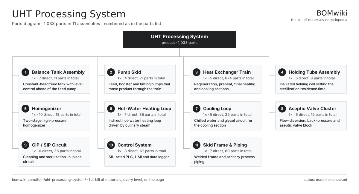
| # | Part | Qty | What it does |
|---|---|---|---|
| 1 | Balance Tank Assembly 7 parts | 1× | Constant-head feed tank with level control ahead of the feed pump |
| 2 | Pump Skid 4 parts | 1× | Feed, booster and timing pumps that move product through the train |
| 3 | Heat Exchanger Train 5 parts | 1× | Regeneration, preheat, final heating and cooling sections |
| 4 | Holding Tube Assembly 5 parts | 1× | Insulated holding cell setting the sterilization residence time |
| 5 | Homogenizer 10 parts | 1× | Two-stage high-pressure homogenizer |
| 6 | Hot-Water Heating Loop 7 parts | 1× | Indirect hot-water heating loop driven by culinary steam |
| 7 | Cooling Loop 5 parts | 1× | Chilled water and glycol circuit for the cooling section |
| 8 | Aseptic Valve Cluster 6 parts | 1× | Flow-diversion, back-pressure and aseptic valve block |
| 9 | CIP / SIP Circuit 6 parts | 1× | Cleaning and sterilization-in-place circuit |
| 10 | Control System 8 parts | 1× | SIL-rated PLC, HMI and data logger |
| 11 | Skid Frame & Piping 7 parts | 1× | Welded frame and sanitary process piping |
3D model
No 3D model yet. Have a CAD file of this? Add a 3D model — STL renders right on this page; STEP, FreeCAD, and OpenSCAD sources are welcome too (openly licensed, like all 3D models on BOMwiki).
Build & assembly graph
expand / collapse · shared sub-assemblies converge · links to related products · est. labourTap an assembly to expand/collapse · tap a part to open it · use “Open page” for any node · drag to pan, scroll to zoom.
Bill of materials for UHT Processing System
11 top-level lines · 146 rows shown · 1,033 parts total · indented to 3 levels| # | Item / sub-assembly | Part no. | Qty/assy | Ext. qty | Parts | Type |
|---|---|---|---|---|---|---|
| 1 | Balance Tank Assembly 7 parts | uht-processing-system-balance-tank | 1× | 1 | 11 | assembly |
| 1.1 | Tank Shell | uht-processing-system-tank-shell | 1× | 1 | · | part |
| 1.2 | Float Valve | uht-processing-system-tank-float-valve | 1× | 1 | · | part |
| 1.3 | Level Probe | uht-processing-system-level-probe | 2× | 2 | · | part |
| 1.4 | Tank Lid | uht-processing-system-tank-lid | 1× | 1 | · | part |
| 1.5 | Sterile Vent Filter | uht-processing-system-vent-filter | 1× | 1 | · | part |
| 1.6 | Tank Outlet Flange | uht-processing-system-tank-outlet | 1× | 1 | · | part |
| 1.7 | O-Ring Set | oring-set | 4× | 4 | · | part |
| 2 | Pump Skid 4 parts | uht-processing-system-pump-skid | 1× | 1 | 71 | assembly |
| 2.1 | Feed Pump 8 parts | uht-processing-system-feed-pump | 1× | 1 | 30 | assembly |
| 2.1.1 | Pump Casing | uht-processing-system-pump-casing | 1× | 1 | · | part |
| 2.1.2 | Pump Impeller | uht-processing-system-pump-impeller | 1× | 1 | · | part |
| 2.1.3 | Mechanical Seal | uht-processing-system-mech-seal | 1× | 1 | · | part |
| 2.1.4 | Pump Shaft | uht-processing-system-pump-shaft | 1× | 1 | · | part |
| 2.1.5 | Stator Assembly 3 parts + deeper › | stator-assembly | 1× | 1 | 3 | assembly |
| 2.1.6 | Rotor Assembly 4 parts + deeper › | rotor-assembly | 1× | 1 | 19 | assembly |
| 2.1.7 | Ball Bearing | ball-bearing | 2× | 2 | · | part |
| 2.1.8 | Oil Seal | oil-seal | 2× | 2 | · | part |
| 2.2 | Aseptic Booster Pump 6 parts | uht-processing-system-booster-pump | 1× | 1 | 27 | assembly |
| 2.2.1 | Pump Casing | uht-processing-system-pump-casing | 1× | 1 | · | part |
| 2.2.2 | Pump Impeller | uht-processing-system-pump-impeller | 1× | 1 | · | part |
| 2.2.3 | Mechanical Seal | uht-processing-system-mech-seal | 1× | 1 | · | part |
| 2.2.4 | Stator Assembly 3 parts + deeper › | stator-assembly | 1× | 1 | 3 | assembly |
| 2.2.5 | Rotor Assembly 4 parts + deeper › | rotor-assembly | 1× | 1 | 19 | assembly |
| 2.2.6 | Ball Bearing | ball-bearing | 2× | 2 | · | part |
| 2.3 | Timing Pump 6 parts | uht-processing-system-timing-pump | 1× | 1 | 11 | assembly |
| 2.3.1 | Lobe Rotor | uht-processing-system-lobe-rotor | 2× | 2 | · | part |
| 2.3.2 | Lobe Pump Housing | uht-processing-system-pump-housing | 1× | 1 | · | part |
| 2.3.3 | Helical Gear Pair | gear-pair | 1× | 1 | · | part |
| 2.3.4 | Gearbox Housing | gearbox-housing | 1× | 1 | · | part |
| 2.3.5 | Ball Bearing | ball-bearing | 4× | 4 | · | part |
| 2.3.6 | Oil Seal | oil-seal | 2× | 2 | · | part |
| 2.4 | Variable-Frequency Drive | uht-processing-system-vfd | 3× | 3 | · | part |
| 3 | Heat Exchanger Train 5 parts | uht-processing-system-heat-exchanger-train | 1× | 1 | 674 | assembly |
| 3.1 | Regeneration Section 3 parts | uht-processing-system-regen-section | 1× | 1 | 242 | assembly |
| 3.1.1 | Heat Transfer Plate | uht-processing-system-heat-plate | 120× | 120 | · | part |
| 3.1.2 | Plate Gasket | uht-processing-system-plate-gasket | 120× | 120 | · | part |
| 3.1.3 | O-Ring Set | oring-set | 2× | 2 | · | part |
| 3.2 | Preheat Section 2 parts | uht-processing-system-preheat-section | 1× | 1 | 120 | assembly |
| 3.2.1 | Heat Transfer Plate | uht-processing-system-heat-plate | 60× | 60 | · | part |
| 3.2.2 | Plate Gasket | uht-processing-system-plate-gasket | 60× | 60 | · | part |
| 3.3 | Final Heating Section 2 parts | uht-processing-system-final-heat-section | 1× | 1 | 160 | assembly |
| 3.3.1 | Heat Transfer Plate | uht-processing-system-heat-plate | 80× | 80 | · | part |
| 3.3.2 | Plate Gasket | uht-processing-system-plate-gasket | 80× | 80 | · | part |
| 3.4 | Cooling Section 2 parts | uht-processing-system-cooling-section | 1× | 1 | 140 | assembly |
| 3.4.1 | Heat Transfer Plate | uht-processing-system-heat-plate | 70× | 70 | · | part |
| 3.4.2 | Plate Gasket | uht-processing-system-plate-gasket | 70× | 70 | · | part |
| 3.5 | PHE Frame 5 parts | uht-processing-system-phe-frame | 1× | 1 | 12 | assembly |
| 3.5.1 | Frame Plate | uht-processing-system-frame-plate | 1× | 1 | · | part |
| 3.5.2 | Pressure Plate | uht-processing-system-pressure-plate | 1× | 1 | · | part |
| 3.5.3 | Carry Bar | uht-processing-system-carry-bar | 1× | 1 | · | part |
| 3.5.4 | Tie Bolt | uht-processing-system-tie-bolt | 8× | 8 | · | part |
| 3.5.5 | Fastener Set | fastener-set | 1× | 1 | · | part |
| 4 | Holding Tube Assembly 5 parts | uht-processing-system-holding-tube | 1× | 1 | 8 | assembly |
| 4.1 | Holding Coil | uht-processing-system-holding-coil | 1× | 1 | · | part |
| 4.2 | Tube Insulation Jacket | uht-processing-system-tube-insulation | 1× | 1 | · | part |
| 4.3 | Inlet RTD | uht-processing-system-inlet-rtd | 1× | 1 | · | part |
| 4.4 | Outlet RTD | uht-processing-system-outlet-rtd | 1× | 1 | · | part |
| 4.5 | Tube Support Bracket | uht-processing-system-tube-support | 4× | 4 | · | part |
| 5 | Homogenizer 10 parts | uht-processing-system-homogenizer | 1× | 1 | 18 | assembly |
| 5.1 | Pump Block | uht-processing-system-homog-block | 1× | 1 | · | part |
| 5.2 | Ceramic Plunger | uht-processing-system-plunger | 3× | 3 | · | part |
| 5.3 | First-Stage Valve | uht-processing-system-homog-valve-1 | 1× | 1 | · | part |
| 5.4 | Second-Stage Valve | uht-processing-system-homog-valve-2 | 1× | 1 | · | part |
| 5.5 | Crankcase | uht-processing-system-crankcase | 1× | 1 | · | part |
| 5.6 | Helical Gear Pair | gear-pair | 1× | 1 | · | part |
| 5.7 | Gearbox Housing | gearbox-housing | 1× | 1 | · | part |
| 5.8 | Ball Bearing | ball-bearing | 6× | 6 | · | part |
| 5.9 | Drive Belt | drive-belt | 2× | 2 | · | part |
| 5.10 | O-Ring Set | oring-set | 1× | 1 | · | part |
| 6 | Hot-Water Heating Loop 7 parts | uht-processing-system-steam-loop | 1× | 1 | 35 | assembly |
| 6.1 | Steam Injector | uht-processing-system-steam-injector | 1× | 1 | · | part |
| 6.2 | Hot-Water Pump 5 parts | uht-processing-system-hw-pump | 1× | 1 | 26 | assembly |
| 6.2.1 | Pump Casing | uht-processing-system-pump-casing | 1× | 1 | · | part |
| 6.2.2 | Pump Impeller | uht-processing-system-pump-impeller | 1× | 1 | · | part |
| 6.2.3 | Stator Assembly 3 parts + deeper › | stator-assembly | 1× | 1 | 3 | assembly |
| 6.2.4 | Rotor Assembly 4 parts + deeper › | rotor-assembly | 1× | 1 | 19 | assembly |
| 6.2.5 | Ball Bearing | ball-bearing | 2× | 2 | · | part |
| 6.3 | Expansion Vessel | uht-processing-system-expansion-vessel | 1× | 1 | · | part |
| 6.4 | Steam Control Valve | uht-processing-system-steam-control-valve | 1× | 1 | · | part |
| 6.5 | Steam Trap | uht-processing-system-steam-trap | 2× | 2 | · | part |
| 6.6 | Pressure Sensor | pressure-sensor | 2× | 2 | · | part |
| 6.7 | Loop RTD | uht-processing-system-loop-rtd | 2× | 2 | · | part |
| 7 | Cooling Loop 5 parts | uht-processing-system-cooling-loop | 1× | 1 | 39 | assembly |
| 7.1 | Glycol Chiller 6 parts | uht-processing-system-chiller-unit | 1× | 1 | 9 | assembly |
| 7.1.1 | Scroll Compressor | uht-processing-system-compressor | 1× | 1 | · | part |
| 7.1.2 | Condenser Coil | uht-processing-system-chiller-condenser | 1× | 1 | · | part |
| 7.1.3 | Brazed-Plate Evaporator | uht-processing-system-chiller-evaporator | 1× | 1 | · | part |
| 7.1.4 | Expansion Valve | uht-processing-system-expansion-valve | 1× | 1 | · | part |
| 7.1.5 | Power Supply | power-supply | 1× | 1 | · | part |
| 7.1.6 | Relay | relay | 4× | 4 | · | part |
| 7.2 | Chilled-Water Pump 5 parts | uht-processing-system-cw-pump | 1× | 1 | 26 | assembly |
| 7.2.1 | Pump Casing | uht-processing-system-pump-casing | 1× | 1 | · | part |
| 7.2.2 | Pump Impeller | uht-processing-system-pump-impeller | 1× | 1 | · | part |
| 7.2.3 | Stator Assembly 3 parts + deeper › | stator-assembly | 1× | 1 | 3 | assembly |
| 7.2.4 | Rotor Assembly 4 parts + deeper › | rotor-assembly | 1× | 1 | 19 | assembly |
| 7.2.5 | Ball Bearing | ball-bearing | 2× | 2 | · | part |
| 7.3 | Glycol Buffer Tank | uht-processing-system-glycol-tank | 1× | 1 | · | part |
| 7.4 | Cooling Control Valve | uht-processing-system-cooling-control-valve | 1× | 1 | · | part |
| 7.5 | Loop RTD | uht-processing-system-loop-rtd | 2× | 2 | · | part |
| 8 | Aseptic Valve Cluster 6 parts | uht-processing-system-valve-cluster | 1× | 1 | 19 | assembly |
| 8.1 | Flow-Diversion Valve | uht-processing-system-flow-diversion-valve | 1× | 1 | · | part |
| 8.2 | Back-Pressure Valve | uht-processing-system-back-pressure-valve | 1× | 1 | · | part |
| 8.3 | Aseptic Valve | uht-processing-system-aseptic-valve | 6× | 6 | · | part |
| 8.4 | Aseptic Sample Valve | uht-processing-system-sample-valve | 2× | 2 | · | part |
| 8.5 | Pneumatic Actuator | uht-processing-system-actuator | 8× | 8 | · | part |
| 8.6 | Magnetic Flow Meter | uht-processing-system-flow-meter | 1× | 1 | · | part |
| 9 | CIP / SIP Circuit 6 parts | uht-processing-system-cip-circuit | 1× | 1 | 36 | assembly |
| 9.1 | CIP Tank | uht-processing-system-cip-tank | 2× | 2 | · | part |
| 9.2 | CIP Pump 5 parts | uht-processing-system-cip-pump | 1× | 1 | 26 | assembly |
| 9.2.1 | Pump Casing | uht-processing-system-pump-casing | 1× | 1 | · | part |
| 9.2.2 | Pump Impeller | uht-processing-system-pump-impeller | 1× | 1 | · | part |
| 9.2.3 | Stator Assembly 3 parts + deeper › | stator-assembly | 1× | 1 | 3 | assembly |
| 9.2.4 | Rotor Assembly 4 parts + deeper › | rotor-assembly | 1× | 1 | 19 | assembly |
| 9.2.5 | Ball Bearing | ball-bearing | 2× | 2 | · | part |
| 9.3 | CIP Heater | uht-processing-system-cip-heater | 1× | 1 | · | part |
| 9.4 | Dosing Pump | uht-processing-system-dosing-pump | 2× | 2 | · | part |
| 9.5 | Conductivity Sensor | uht-processing-system-conductivity-sensor | 1× | 1 | · | part |
| 9.6 | Heating Element | heating-element | 4× | 4 | · | part |
| 10 | Control System 8 parts | uht-processing-system-control-system | 1× | 1 | 62 | assembly |
| 10.1 | Safety PLC | uht-processing-system-plc | 1× | 1 | · | part |
| 10.2 | I/O Module 5 parts | uht-processing-system-io-module | 6× | 6 | 6 | assembly |
| 10.2.1 | Bare PCB | pcb-bare | 1× | 6 | · | part |
| 10.2.2 | Microcontroller | mcu | 1× | 6 | · | part |
| 10.2.3 | SMD Passive (R/C/L) | smd-passives | 1× | 6 | · | part |
| 10.2.4 | Connector | connector | 2× | 12 | · | part |
| 10.2.5 | CAN Transceiver | can-transceiver | 1× | 6 | · | part |
| 10.3 | HMI Panel 5 parts | uht-processing-system-hmi-panel | 1× | 1 | 5 | assembly |
| 10.3.1 | LCD Panel | lcd-panel | 1× | 1 | · | part |
| 10.3.2 | Bare PCB | pcb-bare | 1× | 1 | · | part |
| 10.3.3 | Microcontroller | mcu | 1× | 1 | · | part |
| 10.3.4 | Power Supply | power-supply | 1× | 1 | · | part |
| 10.3.5 | Wire Bundle | wire-bundle | 1× | 1 | · | part |
| 10.4 | Data Logger | uht-processing-system-data-logger | 1× | 1 | · | part |
| 10.5 | Control Cabinet | uht-processing-system-control-cabinet | 1× | 1 | · | part |
| 10.6 | Power Supply | power-supply | 2× | 2 | · | part |
| 10.7 | Relay | relay | 12× | 12 | · | part |
| 10.8 | Pressure Sensor | pressure-sensor | 4× | 4 | · | part |
| 11 | Skid Frame & Piping 7 parts | uht-processing-system-skid-frame | 1× | 1 | 60 | assembly |
| 11.1 | Base Frame | uht-processing-system-base-frame | 1× | 1 | · | part |
| 11.2 | Leveling Foot | uht-processing-system-leveling-foot | 6× | 6 | · | part |
| 11.3 | Process Pipe Set | uht-processing-system-process-pipe | 1× | 1 | · | part |
| 11.4 | Tri-Clamp Union | uht-processing-system-pipe-clamp | 40× | 40 | · | part |
| 11.5 | Sheet Metal Panel | sheet-panel | 6× | 6 | · | part |
| 11.6 | Fastener Set | fastener-set | 2× | 2 | · | part |
| 11.7 | O-Ring Set | oring-set | 4× | 4 | · | part |
Related products
same domain, ranked by shared parts Grain Color Sorter
3,056 parts · shares 18 with this page
Grain Color Sorter
3,056 parts · shares 18 with this page
 Edible Oil Refining Line
3,224 parts · shares 23 with this page
Egg Breaking and Separating Line
1,126 parts · shares 23 with this page
Edible Oil Refining Line
3,224 parts · shares 23 with this page
Egg Breaking and Separating Line
1,126 parts · shares 23 with this page
 Juice Extraction Line
399 parts · shares 23 with this page
Tubular Sterilizer
221 parts · shares 23 with this page
Juice Extraction Line
399 parts · shares 23 with this page
Tubular Sterilizer
221 parts · shares 23 with this page
Sourcing: possible vendors
Prices, MOQ, and lead times are algorithmic estimates, not quotes, and not claims about these companies. Company mappings are curated by keyword; est. price band $1k–$500k. How estimates work| Vendor | HQ | Specialty | MOQ | Lead time |
|---|---|---|---|---|
| gea.com ↗ | Düsseldorf, DE | Process technology | 20 units | 12–20 wks |
| buhlergroup.com ↗ | Uzwil, CH | Food & materials processing | 20 units | 12–20 wks |
| tetrapak.com ↗ | Pully, CH | Food packaging & processing | 20 units | 12–20 wks |
| jbtc.com ↗ | Chicago, US | Food processing equipment | 20 units | 12–20 wks |
| alfalaval.com ↗ | Lund, SE | Heat transfer & separation | 20 units | 12–20 wks |
1,124-word article