Membrane Filtration Skid
ProductOverview
A membrane filtration skid separates and concentrates liquid food by pushing it across a semi-permeable membrane under pressure. Small molecules and water pass through as permeate while larger molecules and particles are held back and concentrated as retentate. Nothing is heated and nothing changes phase, so the process is gentle on proteins, flavors, and live cultures. This is why dairies, juice plants, and plant-protein producers rely on it.
The skid is a packaged, piped-up system built around banks of Pressure Housing vessels, each holding several Spiral-Wound Membrane Element cartridges, plus the pumps, valves, instruments, and cleaning circuit needed to run them. The choice of membrane sets what the skid does: microfiltration removes bacteria and fat globules, ultrafiltration concentrates protein, nanofiltration removes salts and small sugars, and reverse osmosis concentrates by removing water.
How it works
Feed is conditioned in the Pretreatment Module module, then the High-Pressure Feed Pump raises it to operating pressure and sends it into the Membrane Array. Inside each Pressure Housing, product flows along the surface of the spiral-wound membrane rather than dead-ending into it. This tangential, or cross-flow, motion is what keeps the membrane from blinding over. The Feed Channel Spacer mesh inside each element holds the flow channel open and creates turbulence that sweeps rejected material away from the membrane face.
Permeate that passes through the Membrane Sheet spirals inward to the Permeate Collection Tube at the core of each element and is collected. Retentate that does not pass through continues down the series of elements, getting steadily more concentrated. The Recirculation Booster Pump boosts the flow around a recirculation loop so cross-flow velocity stays high even as feed is consumed.
Membrane array
The heart of the skid is the Membrane Array. Three to six Spiral-Wound Membrane Element cartridges sit end to end inside a single Pressure Housing, joined by Permeate Interconnector permeate couplings and sealed against the housing wall by an Element Brine Seal brine seal that forces all feed through the elements rather than around them. The Anti-Telescoping Device caps on each element stop the rolled membrane from sliding apart under the pressure drop. Several housings are plumbed in parallel banks to reach the required flow, and the banks are arranged in a tapered array so velocity stays constant as volume drops.
Pumps and pressure
The High-Pressure Feed Pump is a multistage centrifugal pump, with each Pump Stage (Impeller + Diffuser) adding head until the array reaches its operating pressure, which can be 2 bar for microfiltration or 40 bar for reverse osmosis. A sanitary Mechanical Seal with a Seal Face (SiC) pair of silicon carbide faces keeps lubricant out of the product. The Recirculation Booster Pump is a lower-head, higher-flow pump dedicated to maintaining cross-flow velocity inside the loop, decoupling flow rate from feed pressure.
Pretreatment and fouling control
Membranes foul, and fouling control is most of the engineering. The Pretreatment Module module protects the elements: a Bag Filter Vessel and two Cartridge Filter Housing housings remove suspended solids that would clog the Feed Channel Spacer, while a Chemical Dosing Pump meters antiscalant or acid to stop mineral scale on nanofiltration and reverse-osmosis membranes. A Pressure Sensor across the prefilter flags when the Filter Cartridge (5 micron) needs changing.
Cleaning and hygiene
Even with pretreatment, the membranes accumulate a fouling layer, so the Clean-in-Place System runs automated clean-in-place cycles. The CIP Pump circulates caustic to strip protein and fat, acid to dissolve mineral scale, and sometimes enzyme to break down stubborn organic films, all warmed by the CIP Heater. The CIP Changeover Valve changeover valves switch the skid between production and cleaning without breaking any connections. All wetted parts are stainless steel 316L with sanitary Tri-Clamp Fitting fittings so the whole flow path drains and cleans.
Instrumentation and control
The Control System holds the process at its setpoints. Pressure Sensor units on feed, retentate, and permeate let the PLC Module compute transmembrane pressure, the number that tells the operator how fouled the membranes are. An Conductivity Sensor on the permeate confirms separation quality and triggers an alarm if a membrane fails. Magnetic Flow Meter units on permeate and retentate give the recovery ratio. The operator monitors and adjusts everything from the Operator HMI Panel.
Variants and use
Configuration follows the duty. Whey protein concentration uses ultrafiltration to hold back protein while passing lactose and salts. Milk standardization combines microfiltration and ultrafiltration. Juice and plant extracts use reverse osmosis to remove water at ambient temperature, preserving aroma. Ceramic membranes replace the polymeric Membrane Sheet where the feed is hot, abrasive, or chemically harsh. Across all of these the skid layout stays the same: pretreat, pressurize, recirculate across the membrane, and clean on a schedule.
Membrane Filtration Skid parts and their functions
8 top-level parts · 482 parts in total · full bill of materials below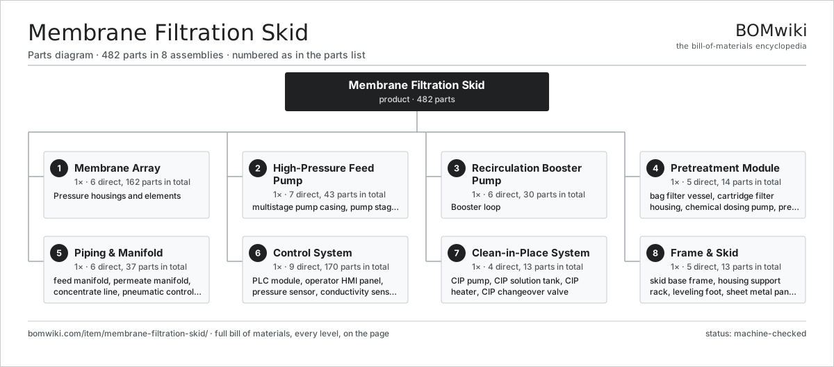
| # | Part | Qty | What it does |
|---|---|---|---|
| 1 | Membrane Array 6 parts | 1× | Pressure housings and elements |
| 2 | High-Pressure Feed Pump 7 parts | 1× | Multistage pump that supplies transmembrane pressure. |
| 3 | Recirculation Booster Pump 6 parts | 1× | Booster loop |
| 4 | Pretreatment Module 5 parts | 1× | Filters and conditions feed before the membranes. |
| 5 | Piping & Manifold 6 parts | 1× | Sanitary feed, concentrate and permeate runs with control valves. |
| 6 | Control System 9 parts | 1× | PLC, sensors and operator interface. |
| 7 | Clean-in-Place System 4 parts | 1× | Flushes membranes with cleaning chemistry on a schedule. |
| 8 | Frame & Skid 5 parts | 1× | Welded stainless frame carrying the housings and pumps. |
3D model
No 3D model yet. Have a CAD file of this? Add a 3D model — STL renders right on this page; STEP, FreeCAD, and OpenSCAD sources are welcome too (openly licensed, like all 3D models on BOMwiki).
Build & assembly graph
expand / collapse · shared sub-assemblies converge · links to related products · est. labourTap an assembly to expand/collapse · tap a part to open it · use “Open page” for any node · drag to pan, scroll to zoom.
Bill of materials for Membrane Filtration Skid
8 top-level lines · 90 rows shown · 482 parts total · indented to 3 levels| # | Item / sub-assembly | Part no. | Qty/assy | Ext. qty | Parts | Type |
|---|---|---|---|---|---|---|
| 1 | Membrane Array 6 parts | mfs-membrane-array | 1× | 1 | 162 | assembly |
| 1.1 | Pressure Housing | mfs-pressure-housing | 6× | 6 | · | part |
| 1.2 | Spiral-Wound Membrane Element 4 parts | mfs-membrane-element | 18× | 18 | 5 | assembly |
| 1.2.1 | Membrane Sheet | mfs-membrane-sheet | 1× | 18 | · | part |
| 1.2.2 | Feed Channel Spacer | mfs-feed-spacer | 1× | 18 | · | part |
| 1.2.3 | Permeate Collection Tube | mfs-permeate-tube | 1× | 18 | · | part |
| 1.2.4 | Anti-Telescoping Device | mfs-anti-telescoping-device | 2× | 36 | · | part |
| 1.3 | Element Brine Seal | mfs-element-seal | 18× | 18 | · | part |
| 1.4 | Permeate Interconnector | mfs-interconnector | 12× | 12 | · | part |
| 1.5 | Housing End Cap | mfs-end-cap | 12× | 12 | · | part |
| 1.6 | O-Ring Set | oring-set | 24× | 24 | · | part |
| 2 | High-Pressure Feed Pump 7 parts | mfs-feed-pump | 1× | 1 | 43 | assembly |
| 2.1 | Multistage Pump Casing | mfs-feed-pump-casing | 1× | 1 | · | part |
| 2.2 | Pump Stage (Impeller + Diffuser) | mfs-pump-stage | 8× | 8 | · | part |
| 2.3 | Pump Shaft | mfs-pump-shaft | 1× | 1 | · | part |
| 2.4 | Mechanical Seal 3 parts | mfs-mechanical-seal | 1× | 1 | 5 | assembly |
| 2.4.1 | Seal Face (SiC) | mfs-seal-face | 2× | 2 | · | part |
| 2.4.2 | Seal Spring | mfs-seal-spring | 1× | 1 | · | part |
| 2.4.3 | O-Ring Set | oring-set | 2× | 2 | · | part |
| 2.5 | Servo Motor 4 parts | servo-motor | 1× | 1 | 24 | assembly |
| 2.5.1 | Stator Assembly 3 parts + deeper › | stator-assembly | 1× | 1 | 3 | assembly |
| 2.5.2 | Rotor Assembly 4 parts + deeper › | rotor-assembly | 1× | 1 | 19 | assembly |
| 2.5.3 | Encoder | encoder | 1× | 1 | · | part |
| 2.5.4 | Motor Housing | motor-housing | 1× | 1 | · | part |
| 2.6 | Ball Bearing | ball-bearing | 2× | 2 | · | part |
| 2.7 | Oil Seal | oil-seal | 2× | 2 | · | part |
| 3 | Recirculation Booster Pump 6 parts | mfs-recirc-pump | 1× | 1 | 30 | assembly |
| 3.1 | Booster Pump Casing | mfs-recirc-casing | 1× | 1 | · | part |
| 3.2 | Booster Impeller | mfs-recirc-impeller | 1× | 1 | · | part |
| 3.3 | Booster Mechanical Seal | mfs-recirc-seal | 1× | 1 | · | part |
| 3.4 | Servo Motor 4 parts | servo-motor | 1× | 1 | 24 | assembly |
| 3.4.1 | Stator Assembly 3 parts + deeper › | stator-assembly | 1× | 1 | 3 | assembly |
| 3.4.2 | Rotor Assembly 4 parts + deeper › | rotor-assembly | 1× | 1 | 19 | assembly |
| 3.4.3 | Encoder | encoder | 1× | 1 | · | part |
| 3.4.4 | Motor Housing | motor-housing | 1× | 1 | · | part |
| 3.5 | Ball Bearing | ball-bearing | 2× | 2 | · | part |
| 3.6 | Oil Seal | oil-seal | 1× | 1 | · | part |
| 4 | Pretreatment Module 5 parts | mfs-pretreatment | 1× | 1 | 14 | assembly |
| 4.1 | Bag Filter Vessel | mfs-bag-filter | 1× | 1 | · | part |
| 4.2 | Cartridge Filter Housing 3 parts | mfs-cartridge-filter | 2× | 2 | 4 | assembly |
| 4.2.1 | Filter Cartridge (5 micron) | mfs-filter-cartridge | 1× | 2 | · | part |
| 4.2.2 | Cartridge Shell | mfs-cartridge-shell | 1× | 2 | · | part |
| 4.2.3 | O-Ring Set | oring-set | 2× | 4 | · | part |
| 4.3 | Chemical Dosing Pump | mfs-dosing-pump | 2× | 2 | · | part |
| 4.4 | Prefilter Housing | mfs-prefilter-housing | 1× | 1 | · | part |
| 4.5 | Pressure Sensor | pressure-sensor | 2× | 2 | · | part |
| 5 | Piping & Manifold 6 parts | mfs-piping-manifold | 1× | 1 | 37 | assembly |
| 5.1 | Feed Manifold | mfs-feed-manifold | 1× | 1 | · | part |
| 5.2 | Permeate Manifold | mfs-permeate-manifold | 1× | 1 | · | part |
| 5.3 | Concentrate Line | mfs-concentrate-line | 1× | 1 | · | part |
| 5.4 | Pneumatic Control Valve 3 parts | mfs-control-valve | 4× | 4 | 4 | assembly |
| 5.4.1 | Valve Body | mfs-valve-body | 1× | 4 | · | part |
| 5.4.2 | Pneumatic Actuator | mfs-valve-actuator | 1× | 4 | · | part |
| 5.4.3 | O-Ring Set | oring-set | 2× | 8 | · | part |
| 5.5 | Magnetic Flow Meter | mfs-flow-meter | 2× | 2 | · | part |
| 5.6 | Tri-Clamp Fitting | mfs-tri-clamp | 16× | 16 | · | part |
| 6 | Control System 9 parts | mfs-control-system | 1× | 1 | 170 | assembly |
| 6.1 | PLC Module 4 parts | mfs-plc | 1× | 1 | 125 | assembly |
| 6.1.1 | Bare PCB | pcb-bare | 1× | 1 | · | part |
| 6.1.2 | Microcontroller | mcu | 1× | 1 | · | part |
| 6.1.3 | SMD Passive (R/C/L) | smd-passives | 120× | 120 | · | part |
| 6.1.4 | I/O Card | mfs-io-card | 3× | 3 | · | part |
| 6.2 | Operator HMI Panel 3 parts | mfs-hmi | 1× | 1 | 3 | assembly |
| 6.2.1 | LCD Panel | lcd-panel | 1× | 1 | · | part |
| 6.2.2 | Touch Glass | mfs-touch-glass | 1× | 1 | · | part |
| 6.2.3 | Bare PCB | pcb-bare | 1× | 1 | · | part |
| 6.3 | Pressure Sensor | pressure-sensor | 6× | 6 | · | part |
| 6.4 | Conductivity Sensor | mfs-conductivity-sensor | 2× | 2 | · | part |
| 6.5 | RTD Temperature Sensor | mfs-temp-sensor | 2× | 2 | · | part |
| 6.6 | Power Supply | power-supply | 1× | 1 | · | part |
| 6.7 | Relay | relay | 6× | 6 | · | part |
| 6.8 | Wire Bundle | wire-bundle | 1× | 1 | · | part |
| 6.9 | Connector | connector | 24× | 24 | · | part |
| 7 | Clean-in-Place System 4 parts | mfs-cip-system | 1× | 1 | 13 | assembly |
| 7.1 | CIP Pump 4 parts | mfs-cip-pump | 1× | 1 | 5 | assembly |
| 7.1.1 | CIP Pump Casing | mfs-cip-pump-casing | 1× | 1 | · | part |
| 7.1.2 | CIP Impeller | mfs-cip-impeller | 1× | 1 | · | part |
| 7.1.3 | Ball Bearing | ball-bearing | 2× | 2 | · | part |
| 7.1.4 | Oil Seal | oil-seal | 1× | 1 | · | part |
| 7.2 | CIP Solution Tank | mfs-cip-tank | 2× | 2 | · | part |
| 7.3 | CIP Heater 2 parts | mfs-cip-heater | 1× | 1 | 2 | assembly |
| 7.3.1 | Heating Element | heating-element | 1× | 1 | · | part |
| 7.3.2 | Heater Shell | mfs-heater-shell | 1× | 1 | · | part |
| 7.4 | CIP Changeover Valve | mfs-cip-valve | 4× | 4 | · | part |
| 8 | Frame & Skid 5 parts | mfs-frame-skid | 1× | 1 | 13 | assembly |
| 8.1 | Skid Base Frame | mfs-skid-base | 1× | 1 | · | part |
| 8.2 | Housing Support Rack | mfs-housing-rack | 1× | 1 | · | part |
| 8.3 | Leveling Foot | mfs-leveling-foot | 6× | 6 | · | part |
| 8.4 | Sheet Metal Panel | sheet-panel | 4× | 4 | · | part |
| 8.5 | Fastener Set | fastener-set | 1× | 1 | · | part |
Related products
same domain, ranked by shared parts Bottle Washing Machine
2,388 parts · shares 22 with this page
Yogurt Production Line
271 parts · shares 22 with this page
Egg Grading and Packing Line
705 parts · shares 22 with this page
Brine Chilling System
239 parts · shares 22 with this page
Bottle Washing Machine
2,388 parts · shares 22 with this page
Yogurt Production Line
271 parts · shares 22 with this page
Egg Grading and Packing Line
705 parts · shares 22 with this page
Brine Chilling System
239 parts · shares 22 with this page
 Forced-Circulation Evaporator
414 parts · shares 22 with this page
Forced-Circulation Evaporator
414 parts · shares 22 with this page
Sourcing: possible vendors
Prices, MOQ, and lead times are algorithmic estimates, not quotes, and not claims about these companies. Company mappings are curated by keyword; est. price band $1k–$500k. How estimates work| Vendor | HQ | Specialty | MOQ | Lead time |
|---|---|---|---|---|
| gea.com ↗ | Düsseldorf, DE | Process technology | 20 units | 12–20 wks |
| buhlergroup.com ↗ | Uzwil, CH | Food & materials processing | 20 units | 12–20 wks |
| tetrapak.com ↗ | Pully, CH | Food packaging & processing | 20 units | 12–20 wks |
| jbtc.com ↗ | Chicago, US | Food processing equipment | 20 units | 12–20 wks |
| alfalaval.com ↗ | Lund, SE | Heat transfer & separation | 20 units | 12–20 wks |
807-word article