Inline Dynamic Mixer
ProductOverview
An inline dynamic mixer blends, disperses, and emulsifies liquid food continuously as it flows through a closed work head, rather than working on a batch in a tank. Product enters one port, passes once through a high-shear rotor-stator stage, and leaves the other port already mixed. Because it is piped directly into a process line and runs continuously, it suits high-volume production of salad dressings, beverages, gum and stabilizer solutions, sauces, and protein slurries.
The inline format has two big advantages over a batch mixer. It gives every portion of product exactly the same, controlled amount of shear, so the result is consistent from the first liter to the last. And it occupies a small footprint in the pipework instead of a large vessel, which matters when floor space is scarce.
How it works
Product is pumped into the Inlet Port and enters the Mixing Chamber. Inside, the High-Shear Rotor spins at high speed within the closely fitted Stator Screen. The rotor blades fling product outward and force it through the narrow slots or holes of the stator at high velocity. The sudden acceleration and the intense shear in the gap break up droplets, disperse powders, and hydrate gums. Product then leaves through the Outlet Port and continues down the line.
Each pass takes a fraction of a second, so the mixer relies on a steady feed rate matched to the rotor speed. The interchangeable Interchangeable Screen Insert sets how aggressive the shear is: a coarse slotted screen for simple blending, a fine-mesh screen for emulsification and droplet reduction.
Mixing chamber and screens
The Mixing Chamber is the heart of the machine. The High-Shear Rotor is a precision multi-blade impeller running with tight clearance inside the Stator Ring. The real tuning happens at the Interchangeable Screen Insert, which slots into the stator and can be swapped to change the duty. Slotted screens give high throughput and gentle dispersion, square-hole screens balance shear and flow, and fine-mesh screens give the finest droplet and particle reduction at the cost of throughput. Changing the screen is a quick way to reconfigure the machine for a different recipe without replacing the whole head.
Rotor shaft and drive
The High-Shear Rotor is carried on the Rotor Shaft, supported by Ball Bearing bearings in the Bearing Cartridge and protected by an Shaft Sleeve where it passes through the seal. The Drive Motor spins the assembly, close-coupled through the Drive Coupling so there is no belt to maintain. Tip speed, the speed of the rotor blade edge, is the number that governs shear intensity, and at 15 to 40 m/s it is high enough to emulsify oil into water and form stable mixtures.
Powder induction
A common reason to choose an inline mixer is its ability to draw dry ingredients straight into the liquid. The Powder Induction Module module sits on the inlet side: as product rushes past the Venturi Inductor, it creates suction that pulls powder down from the Powder Hopper through the Induction Butterfly Valve directly into the shear zone. This wets out and disperses the powder in one step, avoiding the lumps and dust that plague top-of-tank powder addition. The Sight Glass lets the operator watch the induction running. Gums, starches, milk powder, and protein isolates that normally clump are handled cleanly this way.
Sealing and hygiene
Where the Rotor Shaft enters the chamber it is sealed by the Seal System. A sanitary Mechanical Seal with a Seal Face (SiC) pair keeps product off the bearings, and for products that crystallize or dry at the seal an Quench Port supplies a clean flush. All wetted parts are stainless steel 316L joined with Tri-Clamp Fitting sanitary fittings so the unit can be cleaned in place, and the head opens for inspection without breaking the line connections.
Piping and control
The Piping & Ports connect the mixer into the process line through sanitary flanges, with an Bypass Valve so flow can be diverted around the head during startup or cleaning, and an Flow Meter to confirm the feed rate. The Control Panel runs the drive: an Variable Frequency Drive sets rotor speed so shear can be dialed to the recipe, Pressure Sensor units watch inlet and outlet, and the Product Temperature Sensor feeds the Operator HMI Panel so the operator sees whether the product is heating up. Interlocks prevent the rotor from running dry.
Variants and use
A single-stage head suits blending and simple dispersion. A multi-stage head puts two or three rotor-stator pairs in series for finer emulsions in one pass. Self-pumping versions generate enough head to move thin products without a separate feed pump, while non-pumping versions rely on an upstream pump for viscous duty. The powder-induction module is added wherever dry ingredients have to be wetted into the stream. Whatever the configuration, the machine works the same way: one controlled pass through a high-shear gap, applied evenly to a continuous flow.
Inline Dynamic Mixer parts and their functions
8 top-level parts · 215 parts in total · full bill of materials below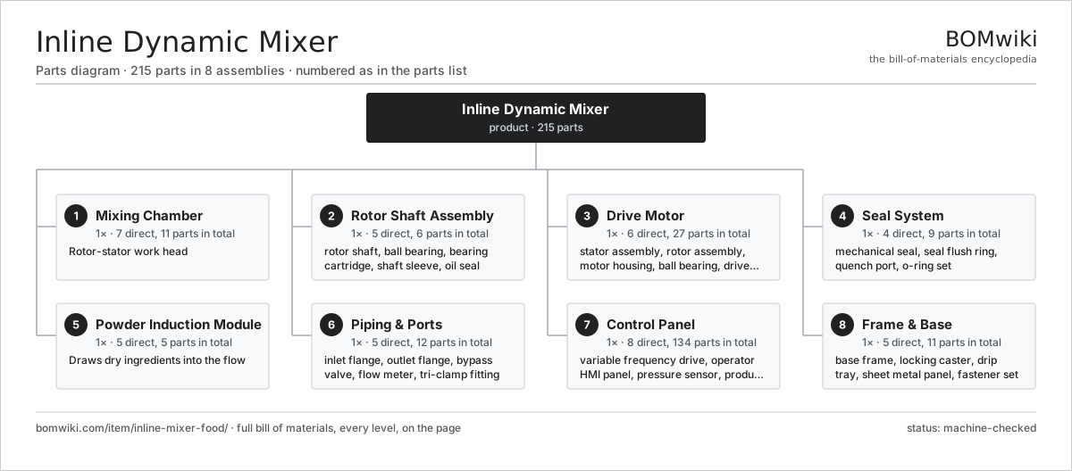
| # | Part | Qty | What it does |
|---|---|---|---|
| 1 | Mixing Chamber 7 parts | 1× | Rotor-stator work head |
| 2 | Rotor Shaft Assembly 5 parts | 1× | Shaft carrying the rotor, supported on a rigid bearing cartridge. |
| 3 | Drive Motor 6 parts | 1× | Close-coupled motor that spins the rotor at 1500-3600 rpm. |
| 4 | Seal System 4 parts | 1× | Single or double mechanical seal keeping product off the bearing. |
| 5 | Powder Induction Module 5 parts | 1× | Draws dry ingredients into the flow |
| 6 | Piping & Ports 5 parts | 1× | Sanitary connections, valves and instrumentation on the flow line. |
| 7 | Control Panel 8 parts | 1× | VFD speed control, interlocks and operator interface. |
| 8 | Frame & Base 5 parts | 1× | Mobile stainless base carrying the motor and work head. |
3D model
No 3D model yet. Have a CAD file of this? Add a 3D model — STL renders right on this page; STEP, FreeCAD, and OpenSCAD sources are welcome too (openly licensed, like all 3D models on BOMwiki).
Build & assembly graph
expand / collapse · shared sub-assemblies converge · links to related products · est. labourTap an assembly to expand/collapse · tap a part to open it · use “Open page” for any node · drag to pan, scroll to zoom.
Bill of materials for Inline Dynamic Mixer
8 top-level lines · 72 rows shown · 215 parts total · indented to 3 levels| # | Item / sub-assembly | Part no. | Qty/assy | Ext. qty | Parts | Type |
|---|---|---|---|---|---|---|
| 1 | Mixing Chamber 7 parts | imf-mixing-chamber | 1× | 1 | 11 | assembly |
| 1.1 | High-Shear Rotor | imf-rotor | 1× | 1 | · | part |
| 1.2 | Stator Screen 2 parts | imf-stator-screen | 1× | 1 | 2 | assembly |
| 1.2.1 | Stator Ring | imf-stator-ring | 1× | 1 | · | part |
| 1.2.2 | Interchangeable Screen Insert | imf-screen-insert | 1× | 1 | · | part |
| 1.3 | Chamber Housing | imf-chamber-housing | 1× | 1 | · | part |
| 1.4 | Inlet Port | imf-inlet-port | 1× | 1 | · | part |
| 1.5 | Outlet Port | imf-outlet-port | 1× | 1 | · | part |
| 1.6 | O-Ring Set | oring-set | 4× | 4 | · | part |
| 1.7 | Fastener Set | fastener-set | 1× | 1 | · | part |
| 2 | Rotor Shaft Assembly 5 parts | imf-rotor-shaft | 1× | 1 | 6 | assembly |
| 2.1 | Rotor Shaft | imf-shaft | 1× | 1 | · | part |
| 2.2 | Ball Bearing | ball-bearing | 2× | 2 | · | part |
| 2.3 | Bearing Cartridge | imf-bearing-cartridge | 1× | 1 | · | part |
| 2.4 | Shaft Sleeve | imf-shaft-sleeve | 1× | 1 | · | part |
| 2.5 | Oil Seal | oil-seal | 1× | 1 | · | part |
| 3 | Drive Motor 6 parts | imf-drive-motor | 1× | 1 | 27 | assembly |
| 3.1 | Stator Assembly 3 parts | stator-assembly | 1× | 1 | 3 | assembly |
| 3.1.1 | Stator Core (laminations) | stator-core | 1× | 1 | · | part |
| 3.1.2 | Copper Winding | copper-winding | 1× | 1 | · | part |
| 3.1.3 | Slot Insulation | stator-insulation | 1× | 1 | · | part |
| 3.2 | Rotor Assembly 4 parts | rotor-assembly | 1× | 1 | 19 | assembly |
| 3.2.1 | Rotor Shaft | rotor-shaft | 1× | 1 | · | part |
| 3.2.2 | Rotor Core | rotor-core | 1× | 1 | · | part |
| 3.2.3 | Neodymium Magnet | neodymium-magnet | 16× | 16 | · | part |
| 3.2.4 | Ball Bearing | ball-bearing | 1× | 1 | · | part |
| 3.3 | Motor Housing | imf-motor-housing | 1× | 1 | · | part |
| 3.4 | Ball Bearing | ball-bearing | 2× | 2 | · | part |
| 3.5 | Drive Coupling | imf-coupling | 1× | 1 | · | part |
| 3.6 | Oil Seal | oil-seal | 1× | 1 | · | part |
| 4 | Seal System 4 parts | imf-seal-system | 1× | 1 | 9 | assembly |
| 4.1 | Mechanical Seal 3 parts | imf-mechanical-seal | 1× | 1 | 5 | assembly |
| 4.1.1 | Seal Face (SiC) | imf-seal-face | 2× | 2 | · | part |
| 4.1.2 | Seal Spring | imf-seal-spring | 1× | 1 | · | part |
| 4.1.3 | O-Ring Set | oring-set | 2× | 2 | · | part |
| 4.2 | Seal Flush Ring | imf-flush-ring | 1× | 1 | · | part |
| 4.3 | Quench Port | imf-quench-port | 1× | 1 | · | part |
| 4.4 | O-Ring Set | oring-set | 2× | 2 | · | part |
| 5 | Powder Induction Module 5 parts | imf-powder-induction | 1× | 1 | 5 | assembly |
| 5.1 | Powder Hopper | imf-powder-hopper | 1× | 1 | · | part |
| 5.2 | Venturi Inductor | imf-venturi | 1× | 1 | · | part |
| 5.3 | Induction Butterfly Valve | imf-induction-valve | 1× | 1 | · | part |
| 5.4 | Induction Pipe | imf-induction-pipe | 1× | 1 | · | part |
| 5.5 | Sight Glass | imf-sight-glass | 1× | 1 | · | part |
| 6 | Piping & Ports 5 parts | imf-piping-ports | 1× | 1 | 12 | assembly |
| 6.1 | Inlet Flange | imf-inlet-flange | 1× | 1 | · | part |
| 6.2 | Outlet Flange | imf-outlet-flange | 1× | 1 | · | part |
| 6.3 | Bypass Valve | imf-bypass-valve | 1× | 1 | · | part |
| 6.4 | Flow Meter | imf-flow-meter | 1× | 1 | · | part |
| 6.5 | Tri-Clamp Fitting | imf-tri-clamp | 8× | 8 | · | part |
| 7 | Control Panel 8 parts | imf-control-panel | 1× | 1 | 134 | assembly |
| 7.1 | Variable Frequency Drive 4 parts | imf-vfd | 1× | 1 | 108 | assembly |
| 7.1.1 | Bare PCB | pcb-bare | 1× | 1 | · | part |
| 7.1.2 | Microcontroller | mcu | 1× | 1 | · | part |
| 7.1.3 | IGBT Power Module | imf-igbt-module | 6× | 6 | · | part |
| 7.1.4 | SMD Passive (R/C/L) | smd-passives | 100× | 100 | · | part |
| 7.2 | Operator HMI Panel 3 parts | imf-hmi | 1× | 1 | 3 | assembly |
| 7.2.1 | LCD Panel | lcd-panel | 1× | 1 | · | part |
| 7.2.2 | Touch Glass | imf-touch-glass | 1× | 1 | · | part |
| 7.2.3 | Bare PCB | pcb-bare | 1× | 1 | · | part |
| 7.3 | Pressure Sensor | pressure-sensor | 2× | 2 | · | part |
| 7.4 | Product Temperature Sensor | imf-temp-sensor | 1× | 1 | · | part |
| 7.5 | Power Supply | power-supply | 1× | 1 | · | part |
| 7.6 | Relay | relay | 4× | 4 | · | part |
| 7.7 | Wire Bundle | wire-bundle | 1× | 1 | · | part |
| 7.8 | Connector | connector | 14× | 14 | · | part |
| 8 | Frame & Base 5 parts | imf-frame-base | 1× | 1 | 11 | assembly |
| 8.1 | Base Frame | imf-base-frame | 1× | 1 | · | part |
| 8.2 | Locking Caster | imf-caster | 4× | 4 | · | part |
| 8.3 | Drip Tray | imf-drip-tray | 1× | 1 | · | part |
| 8.4 | Sheet Metal Panel | sheet-panel | 4× | 4 | · | part |
| 8.5 | Fastener Set | fastener-set | 1× | 1 | · | part |
Related products
same domain, ranked by shared parts Colloid Mill
212 parts · shares 19 with this page
Disc-Stack Separator
494 parts · shares 19 with this page
Colloid Mill
212 parts · shares 19 with this page
Disc-Stack Separator
494 parts · shares 19 with this page
 Edible Oil Refining Line
3,224 parts · shares 19 with this page
Egg Breaking and Separating Line
1,126 parts · shares 19 with this page
Edible Oil Refining Line
3,224 parts · shares 19 with this page
Egg Breaking and Separating Line
1,126 parts · shares 19 with this page
Sourcing: possible vendors
Prices, MOQ, and lead times are algorithmic estimates, not quotes, and not claims about these companies. Company mappings are curated by keyword; est. price band $1k–$500k. How estimates work| Vendor | HQ | Specialty | MOQ | Lead time |
|---|---|---|---|---|
| gea.com ↗ | Düsseldorf, DE | Process technology | 20 units | 12–20 wks |
| buhlergroup.com ↗ | Uzwil, CH | Food & materials processing | 20 units | 12–20 wks |
| tetrapak.com ↗ | Pully, CH | Food packaging & processing | 20 units | 12–20 wks |
| jbtc.com ↗ | Chicago, US | Food processing equipment | 20 units | 12–20 wks |
| alfalaval.com ↗ | Lund, SE | Heat transfer & separation | 20 units | 12–20 wks |
853-word article