Flash Butt Welding Machine
ProductOverview
A flash butt welder joins two pieces end to end across their full cross-section by bringing the ends together under current so they flash and heat, then forging them together under heavy pressure. No filler is added; the weld is made entirely from the parent metal, which is heated to a plastic, partly molten state at the interface and then upset so the soft, oxidised surface metal is squeezed out and clean metal fuses with clean metal. The signature of the process is the violent shower of sparks during flashing, as small bridges of contact between the ends melt and explode. Flash butt welding makes very strong, full-section joints quickly and is the standard way to weld railway rail into continuous track, to join ring and chain, and to butt-weld bar, tube, and band-saw blades.
The machine grips both ends in Clamp Head assemblies on a heavy Machine Frame, drives the moving end with a Platen Drive, and feeds the current from a Welding Transformer. A Hydraulic Power Unit supplies the clamping and upset force, the Weld Control runs the precise motion and current sequence, and a Weld Trimmer strips the upset flash while it is still hot.
Flashing and upset
The weld is made in two phases. First the moving end is advanced slowly into light contact while current flows, so the tiny points that touch carry enormous current density, melt, and blow apart in a flash; the controller keeps advancing to make fresh contacts, and this repeated flashing both heats the ends evenly and burns away their surfaces. When the ends are uniformly hot and slightly molten across the whole face, the second phase fires: the Platen Drive rams them together hard and fast in the upset, squeezing the dirty surface metal and oxide out into a ring of flash and forcing clean metal into clean metal. Because the contaminated surface leaves the joint in the upset, the weld is sound across the full section, which is why the process is trusted for safety-critical joints like rail.
Clamping and alignment
Everything depends on holding the two ends dead in line and not letting them slip during the upset, which applies a very large force. Each Clamp Head closes hardened Clamp Jaw elements with a Clamp Cylinder, seats the work on an Alignment Vee, and passes welding current through a Current Jaw of copper alloy. Current reaches the moving jaw through a Flexible Shunt that flexes as the platen travels. The Machine Frame is massive because the upset reaction runs through the Back Stop and the Frame Tie members, and any flex would misalign the joint.
Driving the motion
Flashing needs a finely controlled, slow advance, and upset needs a fast, powerful stroke, so the Platen Drive is servo-hydraulic. An Upset Cylinder supplies the force, a Servo Valve meters the oil to follow the programmed flashing profile, and a Position Sensor reports the platen position so the Weld Control can shape the motion to the millimetre. The power comes from the Hydraulic Power Unit, where a Hydraulic Pump driven by the Pump Motor charges an Accumulator so the upset can be delivered faster than the pump alone could supply.
Current and control
The Welding Transformer supplies tens of thousands of amperes through a single Secondary Turn, fed from the Primary Winding through a SCR Contactor, with a Tap Changer setting the heat range. The Weld Control is the brain: its Control Board runs the flash-and-upset sequence while the Servo Control Board commands the valve, and a Current Monitor tracks the welding current. Modern rail welders log the full current and displacement record of every weld for traceability, since a track joint that fails can derail a train.
Trimming and use
Upset leaves a thick collar of flash around the joint, which on rail and many bar welds must come off. The Weld Trimmer does this while the metal is still hot and soft: a Trim Cylinder drives profiled Shear Blade elements that shear the flash flush with the parent section in one stroke. The heavy current cycles heat the Current Jaw elements and the transformer, so the Water Cooling loop runs continuously. Flash butt welding is found in rail plants and on mobile track welders, in chain and ring making, in band-saw-blade joining, and wherever a fast, filler-free, full-section butt weld is needed in steel. Its main limits are that it suits matching sections joined end to end rather than complex assemblies, and that the flashing throws sparks and metal that must be contained.
Flash Butt Welding Machine parts and their functions
8 top-level parts · 294 parts in total · full bill of materials below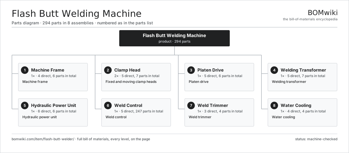
| # | Part | Qty | What it does |
|---|---|---|---|
| 1 | Machine Frame 4 parts | 1× | Machine frame |
| 2 | Clamp Head 5 parts | 2× | Fixed and moving clamp heads |
| 3 | Platen Drive 5 parts | 1× | Platen drive |
| 4 | Welding Transformer 5 parts | 1× | Welding transformer |
| 5 | Hydraulic Power Unit 6 parts | 1× | Hydraulic power unit |
| 6 | Weld Control 5 parts | 1× | Weld control |
| 7 | Weld Trimmer 3 parts | 1× | Weld trimmer |
| 8 | Water Cooling 4 parts | 1× | Water cooling |
3D model
No 3D model yet. Have a CAD file of this? Add a 3D model — STL renders right on this page; STEP, FreeCAD, and OpenSCAD sources are welcome too (openly licensed, like all 3D models on BOMwiki).
Build & assembly graph
expand / collapse · shared sub-assemblies converge · links to related products · est. labourTap an assembly to expand/collapse · tap a part to open it · use “Open page” for any node · drag to pan, scroll to zoom.
Bill of materials for Flash Butt Welding Machine
8 top-level lines · 53 rows shown · 294 parts total · indented to 3 levels| # | Item / sub-assembly | Part no. | Qty/assy | Ext. qty | Parts | Type |
|---|---|---|---|---|---|---|
| 1 | Machine Frame 4 parts | flash-butt-welder-frame | 1× | 1 | 6 | assembly |
| 1.1 | Machine Bed | flash-butt-welder-bed | 1× | 1 | · | part |
| 1.2 | Platen Ways | flash-butt-welder-guide-ways | 2× | 2 | · | part |
| 1.3 | Back Stop | flash-butt-welder-back-stop | 1× | 1 | · | part |
| 1.4 | Frame Tie | flash-butt-welder-frame-tie | 2× | 2 | · | part |
| 2 | Clamp Head 5 parts | flash-butt-welder-clamp-head | 2× | 2 | 7 | assembly |
| 2.1 | Clamp Jaw | flash-butt-welder-clamp-jaw | 2× | 4 | · | part |
| 2.2 | Clamp Cylinder | flash-butt-welder-clamp-cylinder | 1× | 2 | · | part |
| 2.3 | Current Jaw | flash-butt-welder-current-jaw | 1× | 2 | · | part |
| 2.4 | Alignment Vee | flash-butt-welder-alignment-vee | 1× | 2 | · | part |
| 2.5 | Flexible Shunt | flash-butt-welder-flexible-shunt | 2× | 4 | · | part |
| 3 | Platen Drive 5 parts | flash-butt-welder-platen-drive | 1× | 1 | 6 | assembly |
| 3.1 | Upset Cylinder | flash-butt-welder-upset-cylinder | 1× | 1 | · | part |
| 3.2 | Servo Valve | flash-butt-welder-servo-valve | 1× | 1 | · | part |
| 3.3 | Position Sensor | flash-butt-welder-position-sensor | 1× | 1 | · | part |
| 3.4 | Moving Platen | flash-butt-welder-platen | 1× | 1 | · | part |
| 3.5 | Linear Guide Rail | linear-guide | 2× | 2 | · | part |
| 4 | Welding Transformer 5 parts | flash-butt-welder-transformer | 1× | 1 | 7 | assembly |
| 4.1 | Transformer Core | flash-butt-welder-transformer-core | 1× | 1 | · | part |
| 4.2 | Primary Winding | flash-butt-welder-primary-winding | 1× | 1 | · | part |
| 4.3 | Secondary Turn | flash-butt-welder-secondary-turn | 1× | 1 | · | part |
| 4.4 | SCR Contactor 2 parts | flash-butt-welder-scr-contactor | 1× | 1 | 3 | assembly |
| 4.4.1 | Thyristor | flash-butt-welder-thyristor | 2× | 2 | · | part |
| 4.4.2 | Heat Sink | heat-sink | 1× | 1 | · | part |
| 4.5 | Tap Changer | flash-butt-welder-tap-changer | 1× | 1 | · | part |
| 5 | Hydraulic Power Unit 6 parts | flash-butt-welder-hydraulic-unit | 1× | 1 | 6 | assembly |
| 5.1 | Hydraulic Pump | flash-butt-welder-hydraulic-pump | 1× | 1 | · | part |
| 5.2 | Pump Motor | flash-butt-welder-pump-motor | 1× | 1 | · | part |
| 5.3 | Accumulator | flash-butt-welder-accumulator | 1× | 1 | · | part |
| 5.4 | Oil Tank | flash-butt-welder-oil-tank | 1× | 1 | · | part |
| 5.5 | Relief Valve | flash-butt-welder-relief-valve | 1× | 1 | · | part |
| 5.6 | Oil Filter | flash-butt-welder-oil-filter | 1× | 1 | · | part |
| 6 | Weld Control 5 parts | flash-butt-welder-control | 1× | 1 | 247 | assembly |
| 6.1 | Control Board 3 parts | flash-butt-welder-control-board | 1× | 1 | 152 | assembly |
| 6.1.1 | Bare PCB | pcb-bare | 1× | 1 | · | part |
| 6.1.2 | Microcontroller | mcu | 1× | 1 | · | part |
| 6.1.3 | SMD Passive (R/C/L) | smd-passives | 150× | 150 | · | part |
| 6.2 | Servo Control Board 3 parts | flash-butt-welder-servo-board | 1× | 1 | 92 | assembly |
| 6.2.1 | Bare PCB | pcb-bare | 1× | 1 | · | part |
| 6.2.2 | Microcontroller | mcu | 1× | 1 | · | part |
| 6.2.3 | SMD Passive (R/C/L) | smd-passives | 90× | 90 | · | part |
| 6.3 | LCD Panel | lcd-panel | 1× | 1 | · | part |
| 6.4 | Current Monitor | flash-butt-welder-current-monitor | 1× | 1 | · | part |
| 6.5 | Power Supply | power-supply | 1× | 1 | · | part |
| 7 | Weld Trimmer 3 parts | flash-butt-welder-trimmer | 1× | 1 | 4 | assembly |
| 7.1 | Shear Blade | flash-butt-welder-shear-blade | 2× | 2 | · | part |
| 7.2 | Trim Cylinder | flash-butt-welder-trim-cylinder | 1× | 1 | · | part |
| 7.3 | Trimmer Frame | flash-butt-welder-trim-frame | 1× | 1 | · | part |
| 8 | Water Cooling 4 parts | flash-butt-welder-cooling | 1× | 1 | 4 | assembly |
| 8.1 | Cooling Pump | flash-butt-welder-cooling-pump | 1× | 1 | · | part |
| 8.2 | Heat Exchanger | flash-butt-welder-heat-exchanger | 1× | 1 | · | part |
| 8.3 | Water Tank | flash-butt-welder-water-tank | 1× | 1 | · | part |
| 8.4 | Flow Switch | flash-butt-welder-flow-switch | 1× | 1 | · | part |
Related products
same domain, ranked by shared parts Industrial TIG Welder
492 parts · shares 2 with this page
Industrial TIG Welder
492 parts · shares 2 with this page
 Abrasive Flow Machining Machine
279 parts · shares 2 with this page
Abrasive Flow Machining Machine
279 parts · shares 2 with this page
 Aluminum Extrusion Press
365 parts · shares 2 with this page
Aluminum Extrusion Press
365 parts · shares 2 with this page
 Angle Roll Bender
100 parts · shares 2 with this page
Bar Chamfering Machine
1,148 parts · shares 2 with this page
Angle Roll Bender
100 parts · shares 2 with this page
Bar Chamfering Machine
1,148 parts · shares 2 with this page
Sourcing: possible vendors
Prices, MOQ, and lead times are algorithmic estimates, not quotes, and not claims about these companies. Company mappings are curated by keyword; est. price band $10k–$1M. How estimates work| Vendor | HQ | Specialty | MOQ | Lead time |
|---|---|---|---|---|
|
🇩🇪DMG MORI
dmgmori.com ↗
|
Bielefeld, DE | Machine tools | 5 units | 12–20 wks |
|
🇯🇵Mazak
mazak.com ↗
|
Oguchi, JP | Machine tools | 5 units | 12–20 wks |
| haascnc.com ↗ | Oxnard, US | CNC machine tools | 5 units | 12–20 wks |
|
🇯🇵Okuma
okuma.com ↗
|
Niwa, JP | Machine tools | 5 units | 12–20 wks |
|
🇩🇪Trumpf
trumpf.com ↗
|
Ditzingen, DE | Laser & sheet-metal machines | 5 units | 12–20 wks |
875-word article