Forging Trim Press
ProductOverview
A forging trim press removes the flash from a hot forging once the part has been formed in a closed die. In closed-die forging, more metal is put in the cavity than the part needs so the dies fill completely; the surplus escapes into a thin ring around the parting line called flash. The flash has to come off before the forging can move on to coining, heat treatment, or machining. The trim press does this by forcing the forging through a Trim Die whose opening matches the part profile at the parting line. The flash sits proud of that profile, so as the part is pushed through, the flash is sheared off against the sharp die edge and left behind as a ring. The press rates in tonnes of force, usually 100 to 1600 t, because trimming is a shearing operation and the load depends on the length of cut edge and the strength of the metal at temperature, not on stroke length.
Frame and force path
The Press Frame and Bed carries the trimming force in a closed loop. On a straight-side press the Crown Casting sits on two Side Column uprights over the Bed Casting, and four Tie Rod members clamp the stack together. Each rod is pre-tensioned by a Tie Rod Nut so the frame stays in compression and the joints do not open under load. This pre-stress keeps frame deflection small, which matters because punch and die alignment depends on the frame holding its shape during the cut. The whole press stands on Foundation Mount isolators that absorb the snap-through shock when the flash finally shears and the load drops to almost nothing in a few milliseconds. A C-frame is used on smaller presses where the open front eases tool access, but the straight-side frame is stiffer and is preferred at high tonnage.
Drive and slide
Most trim presses use a mechanical Mechanical Drive. A Main Drive Motor runs continuously and spins up a Flywheel through a set of Drive Belt elements. The flywheel stores the energy, so when the Clutch-Brake Unit engages for one stroke, the Eccentric Crankshaft can deliver far more peak power than the motor rating. The crankshaft drives the Connecting Rod, which pushes the Slide and Guides down. The slide runs in Guide Gib guides along the columns so the Punch Holder stays square to the die. A Counterbalance Cylinder cylinder carries the dead weight of the slide so the connecting rod stays in compression, and a Shut Height Screw sets the closed height for each die stack. If the load ever exceeds the rating, a Overload Protector yields and dumps oil before the frame or tooling is damaged.
Trim tooling
The cut happens at the Trim Die Station station. The Trim Punch is shaped to the top of the forging and presses on the part body, not the flash, so it pushes the forging down through the Trim Die. The die edge is the cutting tool: it is sharp and profiled exactly to the parting line, and the flash shears against it as the part passes. Both die and punch run hot, since trimming is done at 900-1100 deg C while the forging is still soft, so the edges are made from hot-work tool steel such as H13 with Cutting Insert sections in the high-wear zones that can be replaced without remaking the die. A Stripper Plate backed by Coil Spring elements pulls the severed flash ring off the punch on the upstroke, and Scrap Cutter knives chop the ring so it falls clear instead of jamming. Die Guide Post pillars hold punch and die in register so the cut clearance stays even all the way round.
Die space, scrap, and hydraulics
The lower tooling sits on the Bolster and Scrap Chute. A Bolster Plate with a Tee-Slot Field field lets the Die Shoe be clamped and centred under the slide, and Hydraulic Die Clamp units grip it for quick die changes. Below the die, the Scrap Chute carries hot flash to a bin while a separate Part Chute routes the trimmed forging to the next operation. The Hydraulic Power Unit supplies the hydraulics: a Hydraulic Pump delivers 200 to 315 bar to the overload protector, die clamps, and counterbalance charge, with an Accumulator holding pressure steady and a Oil Cooler fighting the radiant heat. A Lubrication System system feeds metered oil to the bearings and gibs and sprays release agent through a Die Spray Nozzle nozzle onto the trim edge between strokes.
Control and automation
The Control Cabinet cabinet runs the cycle. A PLC Control engages the clutch for one stroke, watches crank angle through an Encoder, and trips the brake at top dead centre, while a Safety Light Curtain pair guards the die opening. The Operator HMI holds stroke rate, shut height, and spray timing per part number. On automated lines a Part Transfer and Feed system loads and unloads the press: a Feed Arm sets each hot forging into a Locator Nest that registers it to the die edge, and a Unload Arm clears the trimmed part afterward, both carried on a Transfer Slide driven by Servo Motor units. With the transfer running in step with the slide, the press trims part after part with no hand in the die, which is what lets a forging cell keep pace with the hammer or press feeding it.
Forging Trim Press parts and their functions
9 top-level parts · 190 parts in total · full bill of materials below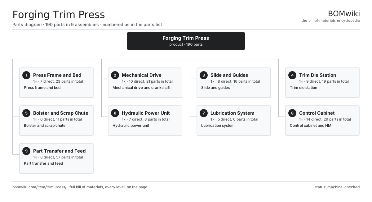
| # | Part | Qty | What it does |
|---|---|---|---|
| 1 | Press Frame and Bed 7 parts | 1× | Press frame and bed |
| 2 | Mechanical Drive 10 parts | 1× | Mechanical drive and crankshaft |
| 3 | Slide and Guides 8 parts | 1× | Slide and guides |
| 4 | Trim Die Station 9 parts | 1× | Trim die station |
| 5 | Bolster and Scrap Chute 6 parts | 1× | Bolster and scrap chute |
| 6 | Hydraulic Power Unit 7 parts | 1× | Hydraulic power unit |
| 7 | Lubrication System 5 parts | 1× | Lubrication system |
| 8 | Control Cabinet 14 parts | 1× | Control cabinet and HMI |
| 9 | Part Transfer and Feed 8 parts | 1× | Part transfer and feed |
3D model
No 3D model yet. Have a CAD file of this? Add a 3D model — STL renders right on this page; STEP, FreeCAD, and OpenSCAD sources are welcome too (openly licensed, like all 3D models on BOMwiki).
Build & assembly graph
expand / collapse · shared sub-assemblies converge · links to related products · est. labourTap an assembly to expand/collapse · tap a part to open it · use “Open page” for any node · drag to pan, scroll to zoom.
Bill of materials for Forging Trim Press
9 top-level lines · 87 rows shown · 190 parts total · indented to 3 levels| # | Item / sub-assembly | Part no. | Qty/assy | Ext. qty | Parts | Type |
|---|---|---|---|---|---|---|
| 1 | Press Frame and Bed 7 parts | trim-press-frame | 1× | 1 | 23 | assembly |
| 1.1 | Crown Casting | trim-press-crown | 1× | 1 | · | part |
| 1.2 | Side Column | trim-press-column | 2× | 2 | · | part |
| 1.3 | Bed Casting | trim-press-bed-casting | 1× | 1 | · | part |
| 1.4 | Tie Rod | trim-press-tie-rod | 4× | 4 | · | part |
| 1.5 | Tie Rod Nut | trim-press-tie-nut | 8× | 8 | · | part |
| 1.6 | Foundation Mount | trim-press-foot-mount | 6× | 6 | · | part |
| 1.7 | Fastener Set | fastener-set | 1× | 1 | · | part |
| 2 | Mechanical Drive 10 parts | trim-press-drive | 1× | 1 | 21 | assembly |
| 2.1 | Main Drive Motor | trim-press-main-motor | 1× | 1 | · | part |
| 2.2 | Flywheel | trim-press-flywheel | 1× | 1 | · | part |
| 2.3 | Clutch-Brake Unit | trim-press-clutch-brake | 1× | 1 | · | part |
| 2.4 | Eccentric Crankshaft | trim-press-crankshaft | 1× | 1 | · | part |
| 2.5 | Connecting Rod | trim-press-connecting-rod | 1× | 1 | · | part |
| 2.6 | Drive Pinion Shaft | trim-press-pinion-shaft | 1× | 1 | · | part |
| 2.7 | Drive Belt | drive-belt | 4× | 4 | · | part |
| 2.8 | Helical Gear Pair | gear-pair | 1× | 1 | · | part |
| 2.9 | Ball Bearing | ball-bearing | 6× | 6 | · | part |
| 2.10 | Oil Seal | oil-seal | 4× | 4 | · | part |
| 3 | Slide and Guides 8 parts | trim-press-slide | 1× | 1 | 16 | assembly |
| 3.1 | Slide Body | trim-press-slide-body | 1× | 1 | · | part |
| 3.2 | Guide Gib | trim-press-gib | 4× | 4 | · | part |
| 3.3 | Overload Protector | trim-press-overload-cylinder | 1× | 1 | · | part |
| 3.4 | Counterbalance Cylinder | trim-press-counterbalance | 2× | 2 | · | part |
| 3.5 | Shut Height Screw | trim-press-shut-height-screw | 1× | 1 | · | part |
| 3.6 | Punch Holder | trim-press-punch-holder | 1× | 1 | · | part |
| 3.7 | Linear Guide Rail | linear-guide | 2× | 2 | · | part |
| 3.8 | Oil Seal | oil-seal | 4× | 4 | · | part |
| 4 | Trim Die Station 9 parts | trim-press-tooling | 1× | 1 | 19 | assembly |
| 4.1 | Trim Die | trim-press-trim-die | 1× | 1 | · | part |
| 4.2 | Trim Punch | trim-press-trim-punch | 1× | 1 | · | part |
| 4.3 | Die Shoe | trim-press-die-shoe | 1× | 1 | · | part |
| 4.4 | Cutting Insert | trim-press-die-insert | 2× | 2 | · | part |
| 4.5 | Scrap Cutter | trim-press-scrap-cutter | 2× | 2 | · | part |
| 4.6 | Stripper Plate | trim-press-stripper | 1× | 1 | · | part |
| 4.7 | Die Guide Post | trim-press-die-guide-post | 4× | 4 | · | part |
| 4.8 | Coil Spring | coil-spring | 6× | 6 | · | part |
| 4.9 | Fastener Set | fastener-set | 1× | 1 | · | part |
| 5 | Bolster and Scrap Chute 6 parts | trim-press-bolster | 1× | 1 | 11 | assembly |
| 5.1 | Bolster Plate | trim-press-bolster-plate | 1× | 1 | · | part |
| 5.2 | Tee-Slot Field | trim-press-tee-slot | 1× | 1 | · | part |
| 5.3 | Scrap Chute | trim-press-scrap-chute | 1× | 1 | · | part |
| 5.4 | Part Chute | trim-press-part-chute | 1× | 1 | · | part |
| 5.5 | Hydraulic Die Clamp | trim-press-die-clamp | 4× | 4 | · | part |
| 5.6 | Sheet Metal Panel | sheet-panel | 3× | 3 | · | part |
| 6 | Hydraulic Power Unit 7 parts | trim-press-hpu | 1× | 1 | 8 | assembly |
| 6.1 | Hydraulic Pump | trim-press-hyd-pump | 1× | 1 | · | part |
| 6.2 | Oil Reservoir | trim-press-hyd-tank | 1× | 1 | · | part |
| 6.3 | Valve Manifold | trim-press-hyd-manifold | 1× | 1 | · | part |
| 6.4 | Accumulator | trim-press-accumulator | 1× | 1 | · | part |
| 6.5 | Oil Cooler | trim-press-hyd-cooler | 1× | 1 | · | part |
| 6.6 | Pressure Sensor | pressure-sensor | 2× | 2 | · | part |
| 6.7 | O-Ring Set | oring-set | 1× | 1 | · | part |
| 7 | Lubrication System 5 parts | trim-press-lubrication | 1× | 1 | 6 | assembly |
| 7.1 | Lube Pump | trim-press-lube-pump | 1× | 1 | · | part |
| 7.2 | Distributor Block | trim-press-lube-distributor | 1× | 1 | · | part |
| 7.3 | Die Spray Nozzle | trim-press-die-spray | 2× | 2 | · | part |
| 7.4 | Lubricant Reservoir | trim-press-lube-tank | 1× | 1 | · | part |
| 7.5 | Pressure Sensor | pressure-sensor | 1× | 1 | · | part |
| 8 | Control Cabinet 14 parts | trim-press-controls | 1× | 1 | 29 | assembly |
| 8.1 | PLC Control | trim-press-plc | 1× | 1 | · | part |
| 8.2 | Operator HMI | trim-press-hmi | 1× | 1 | · | part |
| 8.3 | Drive Module | trim-press-drive-module | 2× | 2 | · | part |
| 8.4 | Safety Light Curtain | trim-press-light-curtain | 2× | 2 | · | part |
| 8.5 | Power Supply | power-supply | 1× | 1 | · | part |
| 8.6 | IGBT Power Module | igbt-module | 2× | 2 | · | part |
| 8.7 | Relay | relay | 6× | 6 | · | part |
| 8.8 | Bare PCB | pcb-bare | 1× | 1 | · | part |
| 8.9 | Microcontroller | mcu | 1× | 1 | · | part |
| 8.10 | SMD Passive (R/C/L) | smd-passives | 1× | 1 | · | part |
| 8.11 | Connector | connector | 8× | 8 | · | part |
| 8.12 | Wire Bundle | wire-bundle | 1× | 1 | · | part |
| 8.13 | LCD Panel | lcd-panel | 1× | 1 | · | part |
| 8.14 | Encoder | encoder | 1× | 1 | · | part |
| 9 | Part Transfer and Feed 8 parts | trim-press-transfer | 1× | 1 | 57 | assembly |
| 9.1 | Feed Arm | trim-press-feed-arm | 1× | 1 | · | part |
| 9.2 | Locator Nest | trim-press-locator-nest | 1× | 1 | · | part |
| 9.3 | Unload Arm | trim-press-unload-arm | 1× | 1 | · | part |
| 9.4 | Transfer Slide | trim-press-transfer-slide | 1× | 1 | · | part |
| 9.5 | Linear Guide Rail | linear-guide | 2× | 2 | · | part |
| 9.6 | Servo Motor 4 parts | servo-motor | 2× | 2 | 24 | assembly |
| 9.6.1 | Stator Assembly 3 parts + deeper › | stator-assembly | 1× | 2 | 3 | assembly |
| 9.6.2 | Rotor Assembly 4 parts + deeper › | rotor-assembly | 1× | 2 | 19 | assembly |
| 9.6.3 | Encoder | encoder | 1× | 2 | · | part |
| 9.6.4 | Motor Housing | motor-housing | 1× | 2 | · | part |
| 9.7 | Pressure Sensor | pressure-sensor | 1× | 1 | · | part |
| 9.8 | Encoder | encoder | 2× | 2 | · | part |
Related products
same domain, ranked by shared parts Rotary-Table Surface Grinder
172 parts · shares 9 with this page
Spline Rolling Machine
138 parts · shares 9 with this page
Rotary-Table Surface Grinder
172 parts · shares 9 with this page
Spline Rolling Machine
138 parts · shares 9 with this page
 Bevel Gear Generator
201 parts · shares 8 with this page
Centering and Facing Machine
1,419 parts · shares 8 with this page
Forging Roll Machine
135 parts · shares 8 with this page
Bevel Gear Generator
201 parts · shares 8 with this page
Centering and Facing Machine
1,419 parts · shares 8 with this page
Forging Roll Machine
135 parts · shares 8 with this page
 Radial Forging Machine
288 parts · shares 8 with this page
Radial Forging Machine
288 parts · shares 8 with this page
Sourcing: possible vendors
Prices, MOQ, and lead times are algorithmic estimates, not quotes, and not claims about these companies. Company mappings are curated by keyword; est. price band $10k–$1M. How estimates work| Vendor | HQ | Specialty | MOQ | Lead time |
|---|---|---|---|---|
|
🇩🇪DMG MORI
dmgmori.com ↗
|
Bielefeld, DE | Machine tools | 5 units | 12–20 wks |
|
🇯🇵Mazak
mazak.com ↗
|
Oguchi, JP | Machine tools | 5 units | 12–20 wks |
| haascnc.com ↗ | Oxnard, US | CNC machine tools | 5 units | 12–20 wks |
|
🇯🇵Okuma
okuma.com ↗
|
Niwa, JP | Machine tools | 5 units | 12–20 wks |
|
🇩🇪Trumpf
trumpf.com ↗
|
Ditzingen, DE | Laser & sheet-metal machines | 5 units | 12–20 wks |
977-word article