Friction Cutoff Saw
ProductOverview
A friction cutoff saw severs steel not by cutting it but by rubbing it hot. A thin toothless steel disc spins so fast that where its rim presses into the stock the contact heats the steel above its softening point in a fraction of a second, and the rim then pushes the softened, partly molten metal out of the kerf. The whole cut takes only seconds even on heavy section, which makes the friction saw one of the fastest cutoff machines for steel. The process is violent: it throws a heavy spark plume, runs very loud, and leaves a hot, burred, heat- affected edge, so it is used where throughput matters more than cut quality, such as tube mills and high-volume bar cutoff.
The machine drives a Friction Blade from a powerful Main Drive through the Spindle Head, all carried on the Machine Frame. A hydraulic Feed System rams the head through the cut, the Clamping holds the stock, and the Spark Enclosure and Control System contain and sequence the process.
How friction cutting works
The Friction Blade is a plain Blade Disc of alloy steel with no real teeth, only a coarse Notched Rim. Counterintuitively, the blade does not need to be harder than the work, because it is not shearing chips. Instead the rim rubs the steel at very high speed, the friction dumps enormous heat into a narrow band, the steel there loses strength, and the blade plows it aside. The blade itself wears slowly and is sacrificial; the notches in the rim pump air that cools the disc between contacts and helps fling the molten steel and sparks clear of the kerf. Because the heat must build faster than it conducts away, the feed has to be fast and the rim speed high.
Spindle and drive
To reach those rim speeds the Spindle Head runs a stiff Spindle in a precise Spindle Housing on preloaded high-speed Ball Bearings, with the thin blade stiffened between large Blade Flanges so it does not wander under the side load. The Main Drive supplies the power: a high-output Drive Motor turns the spindle through a Drive Pulley set and Drive Belts, and a Flywheel stores energy so the blade holds speed when it suddenly bites into the steel. Without that stored energy the cut would stall the moment the rim touched the work.
Frame and feed
Friction cutting generates large, abrupt forces, so the Machine Frame is heavy. A Base Weldment anchors the machine, a Head Column guides the head, and hardened Slideways let it feed without deflecting. The Feed System is hydraulic because the head must be driven through the cut hard and fast: a Feed Cylinder rams the head, a Hydraulic Pump and Feed Valve set the rate, and an Accumulator delivers a fast surge of flow at the start of the cut so the blade enters before it can lose heat.
Clamping, spark control, and control
The Clamping vise locks the stock with two Clamp Jaws driven by Clamp Cylinders, gripping either side of the cut so the section cannot shift under the heavy load, with a Stock Stop for repeat lengths. Because the process throws a large spark and fume plume, the Spark Enclosure wraps the cut zone in Sheet Metal Panels with a Spark Hood, a Extraction Fan pulling the plume to a collector, and a Viewing Window so the operator can watch safely. The Control System sequences the cycle: a Machine PLC brings the blade to speed, drops the feed, and interlocks the guards, all run from the Control Panel.
Use and place among saws
Friction saws live in steel tube mills, structural fabrication lines, and bar cutoff stations where speed per cut is the priority. They handle mild and structural steel best, where the friction-softening mechanism works well, and they cut thin-wall tube extremely fast. They do poorly on aluminium, stainless, and hardened alloys that either melt and gum the blade or resist softening. Compared with a Metal Cutting Band Saw or a Cold Saw, the friction saw trades a clean, square, cool edge for raw cutting rate, so finished parts that need a tidy face are sawn elsewhere or dressed after cutting.
Blade life, safety, and maintenance
The Friction Blade is the central consumable and the main thing the operator manages. Because the disc is sacrificed slowly to the heat and rubbing, it shrinks in diameter over its life and is replaced before it gets too small to reach the work. Blade life depends on holding the right rim speed and feed: too slow and the disc rubs without building enough heat, glazing and overheating itself; too fast a feed and the rim cannot soften the steel ahead of it, which overloads the Spindle and can crack the disc. The large spinning mass and the heavy spark plume make safety central. The Spark Enclosure contains the sparks and molten spatter, the Extraction Fan removes fume, and interlocks tied to the Machine PLC prevent the head from feeding before the blade is at full speed and the guards are closed. Noise is severe, often above the level that requires hearing protection, which is one reason friction saws are giving way to cold saws and carbide circular saws in many shops. Maintenance focuses on the spindle Ball Bearings, which run hot and fast and must be kept in good condition for the disc to track true, on the Drive Belts and Flywheel balance, and on the hydraulic Feed System that must deliver a consistent fast feed cut after cut. Where it survives, it survives on sheer cutting rate for high-volume steel cropping.
Friction Cutoff Saw parts and their functions
8 top-level parts · 62 parts in total · full bill of materials below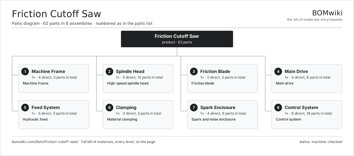
| # | Part | Qty | What it does |
|---|---|---|---|
| 1 | Machine Frame 4 parts | 1× | Machine frame |
| 2 | Spindle Head 5 parts | 1× | High-speed spindle head |
| 3 | Friction Blade 2 parts | 1× | Friction blade |
| 4 | Main Drive 4 parts | 1× | Main drive |
| 5 | Feed System 5 parts | 1× | Hydraulic feed |
| 6 | Clamping 3 parts | 1× | Material clamping |
| 7 | Spark Enclosure 4 parts | 1× | Spark and noise enclosure |
| 8 | Control System 6 parts | 1× | Control system |
3D model
No 3D model yet. Have a CAD file of this? Add a 3D model — STL renders right on this page; STEP, FreeCAD, and OpenSCAD sources are welcome too (openly licensed, like all 3D models on BOMwiki).
Build & assembly graph
expand / collapse · shared sub-assemblies converge · links to related products · est. labourTap an assembly to expand/collapse · tap a part to open it · use “Open page” for any node · drag to pan, scroll to zoom.
Bill of materials for Friction Cutoff Saw
8 top-level lines · 41 rows shown · 62 parts total · indented to 3 levels| # | Item / sub-assembly | Part no. | Qty/assy | Ext. qty | Parts | Type |
|---|---|---|---|---|---|---|
| 1 | Machine Frame 4 parts | friction-cutoff-saw-frame | 1× | 1 | 5 | assembly |
| 1.1 | Base Weldment | friction-cutoff-saw-base-weldment | 1× | 1 | · | part |
| 1.2 | Head Column | friction-cutoff-saw-column | 1× | 1 | · | part |
| 1.3 | Slideway | friction-cutoff-saw-slideway | 2× | 2 | · | part |
| 1.4 | Fastener Set | fastener-set | 1× | 1 | · | part |
| 2 | Spindle Head 5 parts | friction-cutoff-saw-spindle-head | 1× | 1 | 10 | assembly |
| 2.1 | Spindle | friction-cutoff-saw-spindle | 1× | 1 | · | part |
| 2.2 | Spindle Housing | friction-cutoff-saw-spindle-housing | 1× | 1 | · | part |
| 2.3 | Blade Flange | friction-cutoff-saw-blade-flange | 2× | 2 | · | part |
| 2.4 | Ball Bearing | ball-bearing | 4× | 4 | · | part |
| 2.5 | Oil Seal | oil-seal | 2× | 2 | · | part |
| 3 | Friction Blade 2 parts | friction-cutoff-saw-blade | 1× | 1 | 2 | assembly |
| 3.1 | Blade Disc | friction-cutoff-saw-blade-disc | 1× | 1 | · | part |
| 3.2 | Notched Rim | friction-cutoff-saw-notch-edge | 1× | 1 | · | part |
| 4 | Main Drive 4 parts | friction-cutoff-saw-drive | 1× | 1 | 8 | assembly |
| 4.1 | Drive Motor | friction-cutoff-saw-drive-motor | 1× | 1 | · | part |
| 4.2 | Flywheel | friction-cutoff-saw-flywheel | 1× | 1 | · | part |
| 4.3 | Drive Belt | drive-belt | 4× | 4 | · | part |
| 4.4 | Drive Pulley | friction-cutoff-saw-belt-pulley | 2× | 2 | · | part |
| 5 | Feed System 5 parts | friction-cutoff-saw-feed-system | 1× | 1 | 5 | assembly |
| 5.1 | Feed Cylinder | friction-cutoff-saw-feed-cylinder | 1× | 1 | · | part |
| 5.2 | Hydraulic Pump | friction-cutoff-saw-hydraulic-pump | 1× | 1 | · | part |
| 5.3 | Feed Valve | friction-cutoff-saw-feed-valve | 1× | 1 | · | part |
| 5.4 | Accumulator | friction-cutoff-saw-accumulator | 1× | 1 | · | part |
| 5.5 | Pressure Sensor | pressure-sensor | 1× | 1 | · | part |
| 6 | Clamping 3 parts | friction-cutoff-saw-clamping | 1× | 1 | 5 | assembly |
| 6.1 | Clamp Jaw | friction-cutoff-saw-clamp-jaw | 2× | 2 | · | part |
| 6.2 | Clamp Cylinder | friction-cutoff-saw-clamp-cylinder | 2× | 2 | · | part |
| 6.3 | Stock Stop | friction-cutoff-saw-stock-stop | 1× | 1 | · | part |
| 7 | Spark Enclosure 4 parts | friction-cutoff-saw-enclosure | 1× | 1 | 9 | assembly |
| 7.1 | Sheet Metal Panel | sheet-panel | 6× | 6 | · | part |
| 7.2 | Spark Hood | friction-cutoff-saw-spark-hood | 1× | 1 | · | part |
| 7.3 | Extraction Fan | friction-cutoff-saw-extraction-fan | 1× | 1 | · | part |
| 7.4 | Viewing Window | friction-cutoff-saw-view-window | 1× | 1 | · | part |
| 8 | Control System 6 parts | friction-cutoff-saw-control | 1× | 1 | 18 | assembly |
| 8.1 | Machine PLC | friction-cutoff-saw-plc | 1× | 1 | · | part |
| 8.2 | Control Panel | friction-cutoff-saw-control-panel | 1× | 1 | · | part |
| 8.3 | Relay | relay | 6× | 6 | · | part |
| 8.4 | Power Supply | power-supply | 1× | 1 | · | part |
| 8.5 | Connector | connector | 8× | 8 | · | part |
| 8.6 | Wire Bundle | wire-bundle | 1× | 1 | · | part |
Related products
same domain, ranked by shared parts Blacksmith Power Hammer
34 parts · shares 2 with this page
Blanking Press Line
350 parts · shares 2 with this page
Camshaft Grinder
489 parts · shares 2 with this page
Blacksmith Power Hammer
34 parts · shares 2 with this page
Blanking Press Line
350 parts · shares 2 with this page
Camshaft Grinder
489 parts · shares 2 with this page
 Centrifugal Disc Finishing Machine
326 parts · shares 2 with this page
Cold Heading Machine
40 parts · shares 2 with this page
Centrifugal Disc Finishing Machine
326 parts · shares 2 with this page
Cold Heading Machine
40 parts · shares 2 with this page
Sourcing: possible vendors
Prices, MOQ, and lead times are algorithmic estimates, not quotes, and not claims about these companies. Company mappings are curated by keyword; est. price band $10k–$1M. How estimates work| Vendor | HQ | Specialty | MOQ | Lead time |
|---|---|---|---|---|
|
🇩🇪DMG MORI
dmgmori.com ↗
|
Bielefeld, DE | Machine tools | 5 units | 12–20 wks |
|
🇯🇵Mazak
mazak.com ↗
|
Oguchi, JP | Machine tools | 5 units | 12–20 wks |
| haascnc.com ↗ | Oxnard, US | CNC machine tools | 5 units | 12–20 wks |
|
🇯🇵Okuma
okuma.com ↗
|
Niwa, JP | Machine tools | 5 units | 12–20 wks |
|
🇩🇪Trumpf
trumpf.com ↗
|
Ditzingen, DE | Laser & sheet-metal machines | 5 units | 12–20 wks |
1,077-word article