Laser Tube Cutting Machine
ProductOverview
A laser tube cutting machine cuts, notches, and bevels metal tube by melting a narrow line through the wall with a focused laser beam while the tube turns under a head that moves along its length. It replaces a chain of older steps: where a fabricator once sawed tube to length, drilled holes, coped the ends to fit a joint, and deburred each piece, the laser does all of that in one setup from a flat drawing. The work is held by two chucks that grip and spin the tube as a rotary axis, the head rides along the tube as the linear axis, and the controller coordinates the two so the beam traces any shape on the curved surface. The result is a finished part that drops off ready to weld, with slots, holes, tab-and-slot joints, and mitered ends already in place.
The machine carries the Fiber Laser Source that makes the beam, the Cutting Head that focuses it and follows the wall, the Chuck System that grips and rotates the tube, and the Support and Feeding that holds long stock straight and pushes it through. The Motion System moves the head and turns the chucks, the Assist Gas System blows the melt out of the cut, and the Water Chiller keeps the source cool. Around all of it the CNC Controller runs the program, the Fume and Scrap clears smoke and scrap, and the Safety Enclosure keeps the beam contained.
The fiber laser source
The Fiber Laser Source is a fiber laser, the standard choice for metal cutting because it is efficient, has no mirrors to align, and delivers its beam down a flexible fiber. Inside the Fiber Gain Module a length of Doped Fiber is doped with ytterbium, and two Fiber Bragg Grating gratings written into the fiber act as the cavity mirrors that set the 1070 nm wavelength. Banks of Pump Diode Bank feed near-infrared light through a Pump Combiner into that fiber, where it is absorbed and re-emitted as a bright single-mode beam. The Diode Cold Plate holds the diodes at a steady temperature so their wavelength stays matched to the fiber, and a Power Supply drives the whole stack. The beam leaves through an armored Process Fiber and a QBH Connector that mates it to the head.
Rotating head and chucks
The Cutting Head does three jobs at once: it shapes the beam, delivers the assist gas, and stays the right distance from the moving wall. A Collimator first turns the diverging fiber output into a parallel beam, then a Focusing Lens brings it to a small spot at the tube surface, with a cheap Protective Window in front to catch spatter. The Cutting Nozzle shapes the gas jet around that spot, and a Height Sensor reads the gap by capacitance so the machine can hold a constant standoff over the curved, sometimes dented, tube. To cut a clean bevel or to keep the beam square to the wall on a square profile, the Head Rotation Axis axis tilts the whole head on a Servo Motor. The tube itself turns in the Chuck System. A Front Power Chuck near the head and a Rear Chuck at the loading end both center the tube with self-acting jaws, and a Clamp Cylinder sets the grip force. Together they form the rotary cutting axis driven by the Chuck Rotation Drive servo.
Tube handling and feeding
A six metre tube is heavy and flexible, so the Support and Feeding keeps it straight and moves it through the machine in stages. Several Support Rest units hold the mid-span so it does not sag, and Anti-scratch Roller supports let the tube slide without marking a finished surface. The Tube Pusher grips the end and advances the stock as the cut progresses, then ejects the finished length. On a machine fitted with the optional Auto-loader, a pair of Lift Arm units lift tube from a stored bundle and a Singulator drops one piece at a time onto the Loading Area, so the machine can run unattended through a bundle.
Motion and rotary axes
Cutting a shape on a tube takes at least three coordinated axes. The Z Carriage runs the head along the tube on the Linear Guide Rail rails of the Machine Bed, driven by a Ball Screw and a Servo Motor. The Chuck Rotation Drive turns the tube as the rotary axis, and the Head Rotation Axis tilts the head for bevels. Rotary Encoder feedback on the rotary axes lets the controller wrap a flat drawing onto the round or square surface so a hole stays round and a slot stays straight. Because the head and the rotating tube must agree to a fraction of a millimetre, the Base Frame is a heavy stress-relieved weldment that keeps the rails straight under the weight of a long tube.
Controls and support systems
The CNC Controller plans the toolpath from a nest of parts and times the laser, the gas, and the motion together. Its Controller Board and Microcontroller do the path planning, a set of Servo Drive amplifiers power the axes, an I/O Module reads switches and drives valves, and the operator works from the LCD Panel touchscreen. The Assist Gas System system feeds the cut: a Gas Manifold selects oxygen for fast cuts in carbon steel or nitrogen for clean oxide-free edges in stainless, a Proportional Valve sets the pressure, and a Pressure Sensor confirms it at the nozzle. The Water Chiller runs a Coolant Pump and a Compressor to hold the source temperature, and the Fume and Scrap system pulls smoke through a Cartridge Filter while a Scrap Conveyor clears slugs and offcuts.
Use and limits
These machines sit in furniture, exercise equipment, agricultural, and architectural shops, anywhere round, square, and rectangular tube turns into welded frames. They cut carbon steel, stainless, aluminium, brass, and copper, and they cut features that a saw and drill cannot reach, such as interlocking joints that let parts self-locate before welding. The limits follow from the process. Very thick wall slows the cut and at some point a plasma or saw makes more sense. Highly reflective metals like copper need care because they can bounce the beam back toward the source. The laser is a class 4 hazard, so the Safety Enclosure with its Door Interlock doors, its Emergency Stop buttons, and a filtered Viewing Window is required on every machine. Within those limits the machine turns a stack of raw tube and a nest of flat drawings into finished, weld-ready parts with little manual handling.
Laser Tube Cutting Machine parts and their functions
11 top-level parts · 299 parts in total · full bill of materials below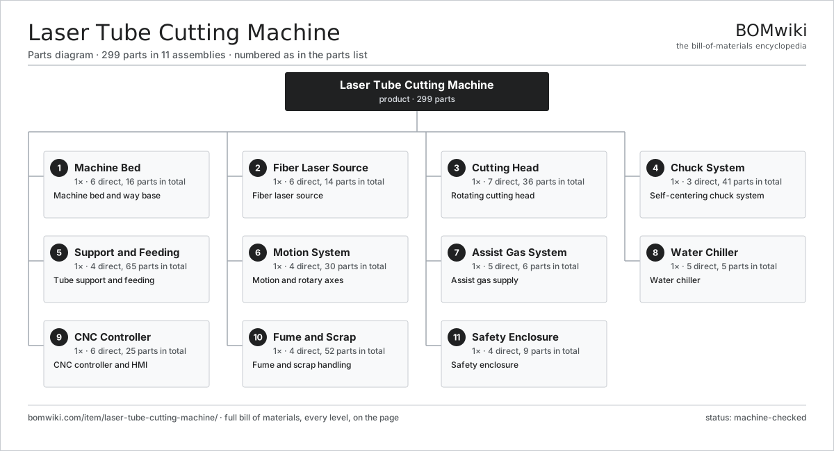
| # | Part | Qty | What it does |
|---|---|---|---|
| 1 | Machine Bed 6 parts | 1× | Machine bed and way base |
| 2 | Fiber Laser Source 6 parts | 1× | Fiber laser source |
| 3 | Cutting Head 7 parts | 1× | Rotating cutting head |
| 4 | Chuck System 3 parts | 1× | Self-centering chuck system |
| 5 | Support and Feeding 4 parts | 1× | Tube support and feeding |
| 6 | Motion System 4 parts | 1× | Motion and rotary axes |
| 7 | Assist Gas System 5 parts | 1× | Assist gas supply |
| 8 | Water Chiller 5 parts | 1× | Water chiller |
| 9 | CNC Controller 6 parts | 1× | CNC controller and HMI |
| 10 | Fume and Scrap 4 parts | 1× | Fume and scrap handling |
| 11 | Safety Enclosure 4 parts | 1× | Safety enclosure |
3D model
No 3D model yet. Have a CAD file of this? Add a 3D model — STL renders right on this page; STEP, FreeCAD, and OpenSCAD sources are welcome too (openly licensed, like all 3D models on BOMwiki).
Build & assembly graph
expand / collapse · shared sub-assemblies converge · links to related products · est. labourTap an assembly to expand/collapse · tap a part to open it · use “Open page” for any node · drag to pan, scroll to zoom.
Bill of materials for Laser Tube Cutting Machine
11 top-level lines · 114 rows shown · 299 parts total · indented to 3 levels| # | Item / sub-assembly | Part no. | Qty/assy | Ext. qty | Parts | Type |
|---|---|---|---|---|---|---|
| 1 | Machine Bed 6 parts | laser-tube-cutting-machine-bed | 1× | 1 | 16 | assembly |
| 1.1 | Base Frame | laser-tube-cutting-machine-base-frame | 1× | 1 | · | part |
| 1.2 | Linear Guide Rail | linear-guide | 2× | 2 | · | part |
| 1.3 | Way Cover | laser-tube-cutting-machine-way-cover | 1× | 1 | · | part |
| 1.4 | Loading Area 2 parts | laser-tube-cutting-machine-loading-area | 1× | 1 | 5 | assembly |
| 1.4.1 | Support Bunk | laser-tube-cutting-machine-load-bunk | 4× | 4 | · | part |
| 1.4.2 | Alignment Stop | laser-tube-cutting-machine-load-stop | 1× | 1 | · | part |
| 1.5 | Leveling Foot | laser-tube-cutting-machine-leveling-foot | 6× | 6 | · | part |
| 1.6 | Fastener Set | fastener-set | 1× | 1 | · | part |
| 2 | Fiber Laser Source 6 parts | laser-tube-cutting-machine-laser-source | 1× | 1 | 14 | assembly |
| 2.1 | Fiber Gain Module 3 parts | laser-tube-cutting-machine-fiber-module | 1× | 1 | 4 | assembly |
| 2.1.1 | Doped Fiber | laser-tube-cutting-machine-doped-fiber | 1× | 1 | · | part |
| 2.1.2 | Fiber Bragg Grating | laser-tube-cutting-machine-fbg | 2× | 2 | · | part |
| 2.1.3 | Pump Combiner | laser-tube-cutting-machine-pump-combiner | 1× | 1 | · | part |
| 2.2 | Pump Diode Bank | laser-tube-cutting-machine-pump-diode | 6× | 6 | · | part |
| 2.3 | Power Supply | power-supply | 1× | 1 | · | part |
| 2.4 | Process Fiber | laser-tube-cutting-machine-process-fiber | 1× | 1 | · | part |
| 2.5 | QBH Connector | laser-tube-cutting-machine-qbh-connector | 1× | 1 | · | part |
| 2.6 | Diode Cold Plate | laser-tube-cutting-machine-source-cooling-plate | 1× | 1 | · | part |
| 3 | Cutting Head 7 parts | laser-tube-cutting-machine-cutting-head | 1× | 1 | 36 | assembly |
| 3.1 | Collimator 2 parts | laser-tube-cutting-machine-collimator | 1× | 1 | 2 | assembly |
| 3.1.1 | Collimating Lens | laser-tube-cutting-machine-collimator-lens | 1× | 1 | · | part |
| 3.1.2 | Collimator Barrel | laser-tube-cutting-machine-collimator-barrel | 1× | 1 | · | part |
| 3.2 | Focusing Lens | laser-tube-cutting-machine-focus-lens | 1× | 1 | · | part |
| 3.3 | Protective Window | laser-tube-cutting-machine-protective-window | 1× | 1 | · | part |
| 3.4 | Cutting Nozzle | laser-tube-cutting-machine-nozzle | 1× | 1 | · | part |
| 3.5 | Height Sensor 3 parts | laser-tube-cutting-machine-height-sensor | 1× | 1 | 3 | assembly |
| 3.5.1 | Capacitive Ring | laser-tube-cutting-machine-cap-ring | 1× | 1 | · | part |
| 3.5.2 | Bare PCB | pcb-bare | 1× | 1 | · | part |
| 3.5.3 | SMD Passive (R/C/L) | smd-passives | 1× | 1 | · | part |
| 3.6 | Head Rotation Axis 3 parts | laser-tube-cutting-machine-head-rotation | 1× | 1 | 27 | assembly |
| 3.6.1 | Servo Motor 4 parts + deeper › | servo-motor | 1× | 1 | 24 | assembly |
| 3.6.2 | Helical Gear Pair | gear-pair | 1× | 1 | · | part |
| 3.6.3 | Ball Bearing | ball-bearing | 2× | 2 | · | part |
| 3.7 | Beam Bellows | laser-tube-cutting-machine-beam-bellows | 1× | 1 | · | part |
| 4 | Chuck System 3 parts | laser-tube-cutting-machine-chuck-system | 1× | 1 | 41 | assembly |
| 4.1 | Front Power Chuck 5 parts | laser-tube-cutting-machine-front-chuck | 1× | 1 | 9 | assembly |
| 4.1.1 | Chuck Body | laser-tube-cutting-machine-chuck-body | 1× | 1 | · | part |
| 4.1.2 | Chuck Jaw | laser-tube-cutting-machine-chuck-jaw | 4× | 4 | · | part |
| 4.1.3 | Clamp Cylinder | laser-tube-cutting-machine-clamp-cylinder | 1× | 1 | · | part |
| 4.1.4 | Scroll Plate | laser-tube-cutting-machine-chuck-scroll | 1× | 1 | · | part |
| 4.1.5 | Ball Bearing | ball-bearing | 2× | 2 | · | part |
| 4.2 | Rear Chuck 4 parts | laser-tube-cutting-machine-rear-chuck | 1× | 1 | 6 | assembly |
| 4.2.1 | Rear Chuck Body | laser-tube-cutting-machine-rear-chuck-body | 1× | 1 | · | part |
| 4.2.2 | Chuck Jaw | laser-tube-cutting-machine-chuck-jaw | 3× | 3 | · | part |
| 4.2.3 | Rear Carriage | laser-tube-cutting-machine-rear-carriage | 1× | 1 | · | part |
| 4.2.4 | Ball Screw | ball-screw | 1× | 1 | · | part |
| 4.3 | Chuck Rotation Drive 3 parts | laser-tube-cutting-machine-chuck-rotation | 1× | 1 | 26 | assembly |
| 4.3.1 | Servo Motor 4 parts + deeper › | servo-motor | 1× | 1 | 24 | assembly |
| 4.3.2 | Helical Gear Pair | gear-pair | 1× | 1 | · | part |
| 4.3.3 | Drive Belt | drive-belt | 1× | 1 | · | part |
| 5 | Support and Feeding 4 parts | laser-tube-cutting-machine-feeding | 1× | 1 | 65 | assembly |
| 5.1 | Support Rest | laser-tube-cutting-machine-support-rest | 4× | 4 | · | part |
| 5.2 | Anti-scratch Roller | laser-tube-cutting-machine-anti-scratch-roller | 8× | 8 | · | part |
| 5.3 | Tube Pusher 3 parts | laser-tube-cutting-machine-tube-pusher | 1× | 1 | 26 | assembly |
| 5.3.1 | Servo Motor 4 parts + deeper › | servo-motor | 1× | 1 | 24 | assembly |
| 5.3.2 | Pusher Gripper | laser-tube-cutting-machine-pusher-gripper | 1× | 1 | · | part |
| 5.3.3 | Linear Guide Rail | linear-guide | 1× | 1 | · | part |
| 5.4 | Auto-loader 3 parts | laser-tube-cutting-machine-loader | 1× | 1 | 27 | assembly |
| 5.4.1 | Lift Arm | laser-tube-cutting-machine-loader-arm | 2× | 2 | · | part |
| 5.4.2 | Singulator | laser-tube-cutting-machine-singulator | 1× | 1 | · | part |
| 5.4.3 | Servo Motor 4 parts + deeper › | servo-motor | 1× | 1 | 24 | assembly |
| 6 | Motion System 4 parts | laser-tube-cutting-machine-motion | 1× | 1 | 30 | assembly |
| 6.1 | Z Carriage 2 parts | laser-tube-cutting-machine-z-carriage | 1× | 1 | 3 | assembly |
| 6.1.1 | Carriage Plate | laser-tube-cutting-machine-carriage-plate | 1× | 1 | · | part |
| 6.1.2 | Linear Guide Rail | linear-guide | 2× | 2 | · | part |
| 6.2 | Ball Screw | ball-screw | 1× | 1 | · | part |
| 6.3 | Servo Motor 4 parts | servo-motor | 1× | 1 | 24 | assembly |
| 6.3.1 | Stator Assembly 3 parts + deeper › | stator-assembly | 1× | 1 | 3 | assembly |
| 6.3.2 | Rotor Assembly 4 parts + deeper › | rotor-assembly | 1× | 1 | 19 | assembly |
| 6.3.3 | Encoder | encoder | 1× | 1 | · | part |
| 6.3.4 | Motor Housing | motor-housing | 1× | 1 | · | part |
| 6.4 | Rotary Encoder | laser-tube-cutting-machine-encoder | 2× | 2 | · | part |
| 7 | Assist Gas System 5 parts | laser-tube-cutting-machine-assist-gas | 1× | 1 | 6 | assembly |
| 7.1 | Gas Manifold | laser-tube-cutting-machine-gas-manifold | 1× | 1 | · | part |
| 7.2 | Gas Regulator | laser-tube-cutting-machine-regulator | 2× | 2 | · | part |
| 7.3 | Proportional Valve | laser-tube-cutting-machine-proportional-valve | 1× | 1 | · | part |
| 7.4 | Pressure Sensor | pressure-sensor | 1× | 1 | · | part |
| 7.5 | O-Ring Set | oring-set | 1× | 1 | · | part |
| 8 | Water Chiller 5 parts | laser-tube-cutting-machine-chiller | 1× | 1 | 5 | assembly |
| 8.1 | Compressor | laser-tube-cutting-machine-compressor | 1× | 1 | · | part |
| 8.2 | Coolant Pump | laser-tube-cutting-machine-coolant-pump | 1× | 1 | · | part |
| 8.3 | Heat Exchanger | laser-tube-cutting-machine-heat-exchanger | 1× | 1 | · | part |
| 8.4 | Coolant Tank | laser-tube-cutting-machine-coolant-tank | 1× | 1 | · | part |
| 8.5 | Pressure Sensor | pressure-sensor | 1× | 1 | · | part |
| 9 | CNC Controller 6 parts | laser-tube-cutting-machine-controller | 1× | 1 | 25 | assembly |
| 9.1 | Controller Board 3 parts | laser-tube-cutting-machine-controller-pcb | 1× | 1 | 8 | assembly |
| 9.1.1 | Bare PCB | pcb-bare | 1× | 1 | · | part |
| 9.1.2 | SMD Passive (R/C/L) | smd-passives | 1× | 1 | · | part |
| 9.1.3 | Connector | connector | 6× | 6 | · | part |
| 9.2 | Microcontroller | mcu | 1× | 1 | · | part |
| 9.3 | Servo Drive | laser-tube-cutting-machine-servo-drive | 5× | 5 | · | part |
| 9.4 | I/O Module 3 parts | laser-tube-cutting-machine-io-module | 1× | 1 | 9 | assembly |
| 9.4.1 | Bare PCB | pcb-bare | 1× | 1 | · | part |
| 9.4.2 | Relay | relay | 4× | 4 | · | part |
| 9.4.3 | Connector | connector | 4× | 4 | · | part |
| 9.5 | LCD Panel | lcd-panel | 1× | 1 | · | part |
| 9.6 | Power Supply | power-supply | 1× | 1 | · | part |
| 10 | Fume and Scrap 4 parts | laser-tube-cutting-machine-fume | 1× | 1 | 52 | assembly |
| 10.1 | Extraction Blower 3 parts | laser-tube-cutting-machine-blower | 1× | 1 | 23 | assembly |
| 10.1.1 | Stator Assembly 3 parts + deeper › | stator-assembly | 1× | 1 | 3 | assembly |
| 10.1.2 | Rotor Assembly 4 parts + deeper › | rotor-assembly | 1× | 1 | 19 | assembly |
| 10.1.3 | Impeller | laser-tube-cutting-machine-impeller | 1× | 1 | · | part |
| 10.2 | Cartridge Filter | laser-tube-cutting-machine-filter | 1× | 1 | · | part |
| 10.3 | Scrap Conveyor 3 parts | laser-tube-cutting-machine-scrap-conveyor | 1× | 1 | 27 | assembly |
| 10.3.1 | Drive Belt | drive-belt | 1× | 1 | · | part |
| 10.3.2 | Servo Motor 4 parts + deeper › | servo-motor | 1× | 1 | 24 | assembly |
| 10.3.3 | Ball Bearing | ball-bearing | 2× | 2 | · | part |
| 10.4 | Wire Bundle | wire-bundle | 1× | 1 | · | part |
| 11 | Safety Enclosure 4 parts | laser-tube-cutting-machine-enclosure | 1× | 1 | 9 | assembly |
| 11.1 | Sheet Metal Panel | sheet-panel | 4× | 4 | · | part |
| 11.2 | Door Interlock | laser-tube-cutting-machine-interlock | 2× | 2 | · | part |
| 11.3 | Emergency Stop | laser-tube-cutting-machine-estop | 2× | 2 | · | part |
| 11.4 | Viewing Window | laser-tube-cutting-machine-viewing-window | 1× | 1 | · | part |
Related products
same domain, ranked by shared parts Crankshaft Grinder
511 parts · shares 8 with this page
Crankshaft Grinder
511 parts · shares 8 with this page
 Creep-Feed Grinder
571 parts · shares 8 with this page
Drag Finishing Machine
735 parts · shares 8 with this page
Creep-Feed Grinder
571 parts · shares 8 with this page
Drag Finishing Machine
735 parts · shares 8 with this page
 Railway Wheel Lathe
1,201 parts · shares 8 with this page
Railway Wheel Lathe
1,201 parts · shares 8 with this page
 Rotary-Table Surface Grinder
172 parts · shares 8 with this page
Rotary-Table Surface Grinder
172 parts · shares 8 with this page
Sourcing: possible vendors
Prices, MOQ, and lead times are algorithmic estimates, not quotes, and not claims about these companies. Company mappings are curated by keyword; est. price band $10k–$1M. How estimates work| Vendor | HQ | Specialty | MOQ | Lead time |
|---|---|---|---|---|
|
🇩🇪DMG MORI
dmgmori.com ↗
|
Bielefeld, DE | Machine tools | 5 units | 12–20 wks |
|
🇯🇵Mazak
mazak.com ↗
|
Oguchi, JP | Machine tools | 5 units | 12–20 wks |
| haascnc.com ↗ | Oxnard, US | CNC machine tools | 5 units | 12–20 wks |
|
🇯🇵Okuma
okuma.com ↗
|
Niwa, JP | Machine tools | 5 units | 12–20 wks |
|
🇩🇪Trumpf
trumpf.com ↗
|
Ditzingen, DE | Laser & sheet-metal machines | 5 units | 12–20 wks |
1,320-word article