Facing Lathe
ProductOverview
A facing lathe, also called a faceplate lathe or bull-nose lathe, is built to turn flat surfaces on large-diameter, short-length parts: flywheels, large flanges, brake discs, valve bodies, gear blanks, pulleys and rings. A normal centre lathe is long and slender, optimised for turning shafts that are far longer than they are wide. A facing lathe inverts that geometry. It has a short, very stiff Bed and Base, a heavy Headstock with a large overhung spindle, and a big Faceplate that holds the disc-shaped work. The tool is carried on a Cross Slide that traverses across the face, so the dominant operation is facing, machining the flat end surface, rather than the long axial turning a centre lathe does. The short bed and large swing let it accept work up to the faceplate diameter, which on big machines reaches 2.5 m.
Bed and base
The Bed and Base is short and massive. The Bed Casting is a stiff grey iron casting that carries the cross-slide ways close to the headstock, because the cutting force on a large overhung disc creates a heavy bending moment that the bed must resist without flexing. It sits on a Base Plinth that raises the work centre to a convenient height and provides foundation mounting. The cross slide rides on wide Cross-Slide Ways, hardened and scraped, with Way Gibs strips to take up clearance. Stiffness is the whole point of the short bed: the same casting that would be wasteful on a long lathe is concentrated here to keep the tool steady against a large, slowly rotating mass.
Headstock and spindle
The Headstock carries the rotating system. The Spindle is a large-bore hollow shaft in 34CrMo4 alloy steel, sized for the high overhung load that a big disc bolted to its nose imposes. It runs in a heavy Spindle Bearing Set set of taper roller bearings that take both the radial cutting force and the bending moment of the work. A Headstock Gearing back-gear train gives the low spindle speeds large diameters need: a 2 m disc at a sensible cutting speed of around 60 m/min turns at only about 10 rpm, so the gearing trades motor speed for the torque to drive a heavy faceplate. The Headstock Casting locates the bearings rigidly and is sealed with Oil Seal elements to keep its oil bath in.
Faceplate and workholding
The defining component is the Faceplate. The Faceplate Disc is a large ground cast iron plate, 600 to 2500 mm across, bolted to the spindle nose. It is cut with radial Faceplate Slots that let the operator clamp the work anywhere across the face and shift its centre to bring a particular feature onto the axis. Work is held by a Clamp Set of dogs, clamps and step blocks. Because faceplate work is often off-centre or asymmetric, adjustable Balance Weights are bolted to the opposite side to counterbalance it. Without balancing, an off-centre load would set up vibration that ruins the finish and stresses the spindle bearings, and at the low speeds these machines run, a well-balanced setup turns smoothly.
Cross slide and tooling
Facing is done by feeding the tool across the rotating face, and that motion comes from the Cross Slide. The Cross Slide Casting rides the bed ways and is driven by a Cross Feed Screw through a Ball Screw, with a Slide Scale reading radial position so the operator can size diameters accurately. The tool itself sits in a Tool Post assembly, usually an indexing Tool Turret that presents several tools in turn so roughing, finishing and boring tools can be brought to the work without re-setting. Quick-change Tool Holders clamp single-point carbide Tool Bit tools. A turret saves a great deal of time on parts that need several operations on the same face.
Feed drive and electrical
Controlled feed is supplied by the Feed Drive. A Feed Gearbox selects the feed in millimetres per revolution and drives the cross-feed screw through a Helical Gear Pair on Ball Bearing supports, with a Feed Clutch engaging and disengaging the automatic feed at the ends of a cut. The Electrical System system centres on a variable-speed Spindle Motor of 7.5–37 kW in a Drive Cabinet, with Relay units, a Power Supply and a Wire Bundle and Connector set handling control and interlocks. Variable speed matters because as the tool feeds outward from the centre, the surface speed at the cutting edge rises with diameter, so the drive can reduce spindle rpm to hold a constant cutting speed and even tool wear across the face.
Coolant, materials and use
The Coolant System uses a Coolant Pump drawing from a Coolant Tank to feed Coolant Nozzle jets at the cutting edge, cooling the tool and washing chips off the flat face where they would otherwise be flung outward by rotation. The bed, headstock and faceplate are grey iron for stiffness and damping; the spindle is alloy steel, and the ways and screws are hardened. Facing lathes are used wherever a part is large in diameter but short in length and needs a flat, true face: machining the faces of large flanges and valve bodies, finishing flywheels and brake discs, facing gear and pulley blanks, and truing the ends of large rings. Typical face flatness is 0.02 to 0.05 mm across the diameter. The short rigid bed, large balanced faceplate and turret tooling make the machine far better suited to this class of work than a long centre lathe.
Facing Lathe parts and their functions
8 top-level parts · 58 parts in total · full bill of materials below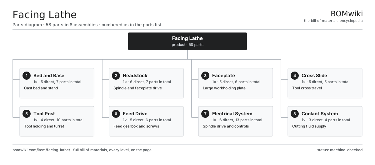
| # | Part | Qty | What it does |
|---|---|---|---|
| 1 | Bed and Base 5 parts | 1× | Cast bed and stand |
| 2 | Headstock 6 parts | 1× | Spindle and faceplate drive |
| 3 | Faceplate 5 parts | 1× | Large workholding plate |
| 4 | Cross Slide 5 parts | 1× | Tool cross travel |
| 5 | Tool Post 4 parts | 1× | Tool holding and turret |
| 6 | Feed Drive 5 parts | 1× | Feed gearbox and screws |
| 7 | Electrical System 6 parts | 1× | Spindle drive and controls |
| 8 | Coolant System 3 parts | 1× | Cutting fluid supply |
3D model
No 3D model yet. Have a CAD file of this? Add a 3D model — STL renders right on this page; STEP, FreeCAD, and OpenSCAD sources are welcome too (openly licensed, like all 3D models on BOMwiki).
Build & assembly graph
expand / collapse · shared sub-assemblies converge · links to related products · est. labourTap an assembly to expand/collapse · tap a part to open it · use “Open page” for any node · drag to pan, scroll to zoom.
Bill of materials for Facing Lathe
8 top-level lines · 47 rows shown · 58 parts total · indented to 3 levels| # | Item / sub-assembly | Part no. | Qty/assy | Ext. qty | Parts | Type |
|---|---|---|---|---|---|---|
| 1 | Bed and Base 5 parts | facing-lathe-bed-base | 1× | 1 | 7 | assembly |
| 1.1 | Bed Casting | facing-lathe-bed-casting | 1× | 1 | · | part |
| 1.2 | Base Plinth | facing-lathe-base-plinth | 1× | 1 | · | part |
| 1.3 | Cross-Slide Ways | facing-lathe-bed-ways | 1× | 1 | · | part |
| 1.4 | Way Gibs | facing-lathe-ways-gib | 2× | 2 | · | part |
| 1.5 | Fastener Set | fastener-set | 2× | 2 | · | part |
| 2 | Headstock 6 parts | facing-lathe-headstock | 1× | 1 | 7 | assembly |
| 2.1 | Spindle | facing-lathe-spindle | 1× | 1 | · | part |
| 2.2 | Spindle Bearing Set | facing-lathe-spindle-bearings | 1× | 1 | · | part |
| 2.3 | Headstock Gearing | facing-lathe-headstock-gears | 1× | 1 | · | part |
| 2.4 | Headstock Casting | facing-lathe-headstock-casting | 1× | 1 | · | part |
| 2.5 | Oil Seal | oil-seal | 2× | 2 | · | part |
| 2.6 | Fastener Set | fastener-set | 1× | 1 | · | part |
| 3 | Faceplate 5 parts | facing-lathe-faceplate | 1× | 1 | 6 | assembly |
| 3.1 | Faceplate Disc | facing-lathe-faceplate-disc | 1× | 1 | · | part |
| 3.2 | Faceplate Slots | facing-lathe-faceplate-slots | 1× | 1 | · | part |
| 3.3 | Balance Weights | facing-lathe-balance-weights | 2× | 2 | · | part |
| 3.4 | Clamp Set | facing-lathe-clamp-set | 1× | 1 | · | part |
| 3.5 | Fastener Set | fastener-set | 1× | 1 | · | part |
| 4 | Cross Slide 5 parts | facing-lathe-cross-slide | 1× | 1 | 5 | assembly |
| 4.1 | Cross Slide Casting | facing-lathe-cross-slide-casting | 1× | 1 | · | part |
| 4.2 | Cross Feed Screw | facing-lathe-cross-feed-screw | 1× | 1 | · | part |
| 4.3 | Slide Scale | facing-lathe-slide-scale | 1× | 1 | · | part |
| 4.4 | Ball Screw | ball-screw | 1× | 1 | · | part |
| 4.5 | Fastener Set | fastener-set | 1× | 1 | · | part |
| 5 | Tool Post 4 parts | facing-lathe-tool-post | 1× | 1 | 10 | assembly |
| 5.1 | Tool Turret | facing-lathe-turret | 1× | 1 | · | part |
| 5.2 | Tool Holders | facing-lathe-tool-holders | 4× | 4 | · | part |
| 5.3 | Tool Bit | facing-lathe-tool-bit | 4× | 4 | · | part |
| 5.4 | Fastener Set | fastener-set | 1× | 1 | · | part |
| 6 | Feed Drive 5 parts | facing-lathe-feed-drive | 1× | 1 | 6 | assembly |
| 6.1 | Feed Gearbox | facing-lathe-feed-gearbox | 1× | 1 | · | part |
| 6.2 | Feed Clutch | facing-lathe-feed-clutch | 1× | 1 | · | part |
| 6.3 | Helical Gear Pair | gear-pair | 1× | 1 | · | part |
| 6.4 | Ball Bearing | ball-bearing | 2× | 2 | · | part |
| 6.5 | Fastener Set | fastener-set | 1× | 1 | · | part |
| 7 | Electrical System 6 parts | facing-lathe-electrical | 1× | 1 | 13 | assembly |
| 7.1 | Spindle Motor | facing-lathe-spindle-motor | 1× | 1 | · | part |
| 7.2 | Drive Cabinet | facing-lathe-drive-cabinet | 1× | 1 | · | part |
| 7.3 | Relay | relay | 3× | 3 | · | part |
| 7.4 | Power Supply | power-supply | 1× | 1 | · | part |
| 7.5 | Wire Bundle | wire-bundle | 1× | 1 | · | part |
| 7.6 | Connector | connector | 6× | 6 | · | part |
| 8 | Coolant System 3 parts | facing-lathe-coolant-system | 1× | 1 | 4 | assembly |
| 8.1 | Coolant Pump | facing-lathe-coolant-pump | 1× | 1 | · | part |
| 8.2 | Coolant Tank | facing-lathe-coolant-tank | 1× | 1 | · | part |
| 8.3 | Coolant Nozzle | facing-lathe-coolant-nozzle | 2× | 2 | · | part |
Related products
same domain, ranked by shared parts Bed-Type Milling Machine
151 parts · shares 2 with this page
Bed-Type Milling Machine
151 parts · shares 2 with this page
 Bevel Gear Generator
201 parts · shares 2 with this page
Centering and Facing Machine
1,419 parts · shares 2 with this page
Bevel Gear Generator
201 parts · shares 2 with this page
Centering and Facing Machine
1,419 parts · shares 2 with this page
 Centerless Grinder
129 parts · shares 2 with this page
CNC Metal Spinning Machine
768 parts · shares 2 with this page
Centerless Grinder
129 parts · shares 2 with this page
CNC Metal Spinning Machine
768 parts · shares 2 with this page
Sourcing: possible vendors
Prices, MOQ, and lead times are algorithmic estimates, not quotes, and not claims about these companies. Company mappings are curated by keyword; est. price band $10k–$1M. How estimates work| Vendor | HQ | Specialty | MOQ | Lead time |
|---|---|---|---|---|
|
🇩🇪DMG MORI
dmgmori.com ↗
|
Bielefeld, DE | Machine tools | 5 units | 12–20 wks |
|
🇯🇵Mazak
mazak.com ↗
|
Oguchi, JP | Machine tools | 5 units | 12–20 wks |
| haascnc.com ↗ | Oxnard, US | CNC machine tools | 5 units | 12–20 wks |
|
🇯🇵Okuma
okuma.com ↗
|
Niwa, JP | Machine tools | 5 units | 12–20 wks |
|
🇩🇪Trumpf
trumpf.com ↗
|
Ditzingen, DE | Laser & sheet-metal machines | 5 units | 12–20 wks |
1,002-word article