Screw Press for Forging
ProductOverview
A screw press, also called a spindle press, is a die-forging machine that delivers its work as a blow rather than a slow squeeze. A Flywheel is spun up to speed, and its stored kinetic energy is driven through a Screw Spindle into the downward travel of the Ram. When the dies close on the hot part the flywheel decelerates, and the blow ends when its energy is spent. This makes the press energy-bound, not force-bound: it is rated in the energy it puts into the part, from a few kJ on small machines to over 1000 kJ on large ones, and the peak force it develops depends on how stiff the part and frame are at the moment of impact. A typical forging press of this kind runs 1.6 to 40 MN nominal force at 8 to 40 blows per minute.
Screw, nut, and flywheel
The core of the machine is the Spindle and Flywheel Assembly assembly. The Screw Spindle, usually forged 34CrNiMo6, has a large lead so that flywheel rotation turns quickly into ram descent. It runs through the Main Nut, a bronze nut fixed in the frame head that carries the full blow reaction in compression and is treated as a wear part. The Flywheel above the nut is the energy store: the larger its inertia and the higher its speed, the more energy each blow can deliver. A Thrust Bearing in the Spindle Housing takes the upward reaction during impact, and a Flywheel Brake stops and reverses the flywheel so the ram returns under control. Spindle guidance runs on Ball Bearing sets sealed by Oil Seal elements.
Ram and frame
The Ram and Slide carries the upper die and is held square to the bed by Ram Gib strips and a Linear Guide Rail pair, which matters because die forging often loads the ram off-centre and would otherwise tip it. The Upper Die Holder clamps the upper die, and a Counterbalance Cylinder cylinder pair supports the ram weight on the return. A Overload Disc sits between ram and die so that a blow landing on a cold or doubled part yields the disc instead of the screw. The whole force loop is the Frame: a Frame Head carrying the nut and flywheel, two Column members, a Bed, and four Tie Rod elements pretensioned by Tie Rod Nut hardware so the joints stay closed under impact. On a blow the frame stretches elastically and stores part of the energy, which it returns on the rebound, so the structure is built stiff and mounted on Shock Mount units that keep the shock off the floor.
Drive
The Drive comes in two forms. A direct servo press couples a large Servo Motor straight to the screw or flywheel and spins it up electrically, with an IGBT Power Module power stage and an Encoder for feedback; the blow energy is set by how far the motor accelerates the flywheel, and the same motor reverses for the return. A friction press instead runs a pair of Friction Disc wheels on a Friction Disc Shaft above the flywheel, and a Clutch Cylinder presses one disc against the flywheel rim to spin it down for the blow and the other to reverse it. The servo type is cleaner and more controllable; the friction type is simpler and long proven. The Drive Coupling and Drive Belt elements transmit the acceleration torque.
Die space, hydraulics, and lubrication
The Die Space and Ejector holds the work tooling: a Bolster raising the Die Block to height, a Die Clamp set locking the dies, and a Ejector Pin group driven by a Ejector Cylinder to lift the hot forging clear after the blow. The Hydraulic Power Unit feeds these circuits: a Hydraulic Pump supplies 200 to 250 bar, a Valve Manifold sequences clamp, counterbalance, and ejector, an Accumulator holds pressure steady, and a Pressure Sensor watches the line. The Lubrication System system meters oil to the screw thread, nut, and guides through a Lubrication Distributor and sprays die release from a Die Spray Nozzle nozzle between blows.
Control and use
The Control Cabinet cabinet houses a PLC Control and a Energy Controller module that sets flywheel spin-up so each stroke delivers the chosen energy and trims it from the measured result. The Operator HMI holds die recipes and blow counts, and power runs through a Power Supply and Relay bank wired by a Wire Bundle. Screw presses suit precision die forging of parts such as turbine blades, fasteners, valve bodies, and gear blanks, where a controlled energy blow fills deep impressions and the bottom dead centre is set by the part rather than a fixed stroke, so die wear and overload are easier to manage than on a hammer.
Screw Press for Forging parts and their functions
8 top-level parts · 138 parts in total · full bill of materials below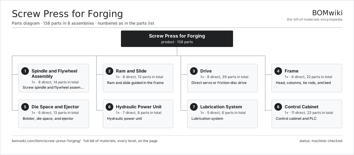
| # | Part | Qty | What it does |
|---|---|---|---|
| 1 | Spindle and Flywheel Assembly 8 parts | 1× | Screw spindle and flywheel assembly |
| 2 | Ram and Slide 8 parts | 1× | Ram and slide guided in the frame |
| 3 | Drive 9 parts | 1× | Direct servo or friction disc drive |
| 4 | Frame 6 parts | 1× | Head, columns, tie rods, and bed |
| 5 | Die Space and Ejector 6 parts | 1× | Bolster, die space, and ejector |
| 6 | Hydraulic Power Unit 7 parts | 1× | Hydraulic power unit |
| 7 | Lubrication System 5 parts | 1× | Lubrication system |
| 8 | Control Cabinet 11 parts | 1× | Control cabinet and PLC |
3D model
No 3D model yet. Have a CAD file of this? Add a 3D model — STL renders right on this page; STEP, FreeCAD, and OpenSCAD sources are welcome too (openly licensed, like all 3D models on BOMwiki).
Build & assembly graph
expand / collapse · shared sub-assemblies converge · links to related products · est. labourTap an assembly to expand/collapse · tap a part to open it · use “Open page” for any node · drag to pan, scroll to zoom.
Bill of materials for Screw Press for Forging
8 top-level lines · 72 rows shown · 138 parts total · indented to 3 levels| # | Item / sub-assembly | Part no. | Qty/assy | Ext. qty | Parts | Type |
|---|---|---|---|---|---|---|
| 1 | Spindle and Flywheel Assembly 8 parts | screw-press-forging-spindle-flywheel | 1× | 1 | 14 | assembly |
| 1.1 | Screw Spindle | screw-press-forging-screw-spindle | 1× | 1 | · | part |
| 1.2 | Main Nut | screw-press-forging-main-nut | 1× | 1 | · | part |
| 1.3 | Flywheel | screw-press-forging-flywheel | 1× | 1 | · | part |
| 1.4 | Thrust Bearing | screw-press-forging-thrust-bearing | 1× | 1 | · | part |
| 1.5 | Spindle Housing | screw-press-forging-spindle-housing | 1× | 1 | · | part |
| 1.6 | Flywheel Brake | screw-press-forging-flywheel-brake | 1× | 1 | · | part |
| 1.7 | Ball Bearing | ball-bearing | 4× | 4 | · | part |
| 1.8 | Oil Seal | oil-seal | 4× | 4 | · | part |
| 2 | Ram and Slide 8 parts | screw-press-forging-ram-slide | 1× | 1 | 13 | assembly |
| 2.1 | Ram | screw-press-forging-ram | 1× | 1 | · | part |
| 2.2 | Ram Gib | screw-press-forging-ram-gib | 4× | 4 | · | part |
| 2.3 | Upper Die Holder | screw-press-forging-upper-die-holder | 1× | 1 | · | part |
| 2.4 | Overload Disc | screw-press-forging-overload-disc | 1× | 1 | · | part |
| 2.5 | Counterbalance Cylinder | screw-press-forging-counterbalance | 2× | 2 | · | part |
| 2.6 | Position Scale | screw-press-forging-position-scale | 1× | 1 | · | part |
| 2.7 | Linear Guide Rail | linear-guide | 2× | 2 | · | part |
| 2.8 | Fastener Set | fastener-set | 1× | 1 | · | part |
| 3 | Drive 9 parts | screw-press-forging-drive | 1× | 1 | 39 | assembly |
| 3.1 | Servo Motor 4 parts | servo-motor | 1× | 1 | 24 | assembly |
| 3.1.1 | Stator Assembly 3 parts + deeper › | stator-assembly | 1× | 1 | 3 | assembly |
| 3.1.2 | Rotor Assembly 4 parts + deeper › | rotor-assembly | 1× | 1 | 19 | assembly |
| 3.1.3 | Encoder | encoder | 1× | 1 | · | part |
| 3.1.4 | Motor Housing | motor-housing | 1× | 1 | · | part |
| 3.2 | Friction Disc | screw-press-forging-friction-disc | 2× | 2 | · | part |
| 3.3 | Friction Disc Shaft | screw-press-forging-disc-shaft | 1× | 1 | · | part |
| 3.4 | Clutch Cylinder | screw-press-forging-clutch-cylinder | 2× | 2 | · | part |
| 3.5 | Drive Coupling | screw-press-forging-drive-coupling | 1× | 1 | · | part |
| 3.6 | IGBT Power Module | igbt-module | 2× | 2 | · | part |
| 3.7 | Encoder | encoder | 1× | 1 | · | part |
| 3.8 | Drive Belt | drive-belt | 2× | 2 | · | part |
| 3.9 | Ball Bearing | ball-bearing | 4× | 4 | · | part |
| 4 | Frame 6 parts | screw-press-forging-frame | 1× | 1 | 22 | assembly |
| 4.1 | Frame Head | screw-press-forging-head | 1× | 1 | · | part |
| 4.2 | Column | screw-press-forging-column | 2× | 2 | · | part |
| 4.3 | Tie Rod | screw-press-forging-tie-rod | 4× | 4 | · | part |
| 4.4 | Bed | screw-press-forging-bed | 1× | 1 | · | part |
| 4.5 | Tie Rod Nut | screw-press-forging-tie-rod-nut | 8× | 8 | · | part |
| 4.6 | Shock Mount | screw-press-forging-shock-mount | 6× | 6 | · | part |
| 5 | Die Space and Ejector 6 parts | screw-press-forging-die-space | 1× | 1 | 13 | assembly |
| 5.1 | Bolster | screw-press-forging-bolster | 1× | 1 | · | part |
| 5.2 | Lower Die Holder | screw-press-forging-lower-die-holder | 1× | 1 | · | part |
| 5.3 | Ejector Pin | screw-press-forging-ejector-pin | 4× | 4 | · | part |
| 5.4 | Ejector Cylinder | screw-press-forging-ejector-cylinder | 1× | 1 | · | part |
| 5.5 | Die Block | screw-press-forging-die-block | 2× | 2 | · | part |
| 5.6 | Die Clamp | screw-press-forging-die-clamp | 4× | 4 | · | part |
| 6 | Hydraulic Power Unit 7 parts | screw-press-forging-hpu | 1× | 1 | 8 | assembly |
| 6.1 | Hydraulic Pump | screw-press-forging-hyd-pump | 1× | 1 | · | part |
| 6.2 | Oil Reservoir | screw-press-forging-hyd-tank | 1× | 1 | · | part |
| 6.3 | Valve Manifold | screw-press-forging-hyd-manifold | 1× | 1 | · | part |
| 6.4 | Accumulator | screw-press-forging-accumulator | 1× | 1 | · | part |
| 6.5 | Oil Cooler | screw-press-forging-hyd-cooler | 1× | 1 | · | part |
| 6.6 | Pressure Sensor | pressure-sensor | 2× | 2 | · | part |
| 6.7 | O-Ring Set | oring-set | 1× | 1 | · | part |
| 7 | Lubrication System 5 parts | screw-press-forging-lubrication | 1× | 1 | 6 | assembly |
| 7.1 | Lubrication Pump | screw-press-forging-lube-pump | 1× | 1 | · | part |
| 7.2 | Lubrication Distributor | screw-press-forging-lube-distributor | 1× | 1 | · | part |
| 7.3 | Die Spray Nozzle | screw-press-forging-die-spray | 2× | 2 | · | part |
| 7.4 | Lubricant Reservoir | screw-press-forging-lube-tank | 1× | 1 | · | part |
| 7.5 | Pressure Sensor | pressure-sensor | 1× | 1 | · | part |
| 8 | Control Cabinet 11 parts | screw-press-forging-controls | 1× | 1 | 23 | assembly |
| 8.1 | PLC Control | screw-press-forging-plc | 1× | 1 | · | part |
| 8.2 | Operator HMI | screw-press-forging-hmi | 1× | 1 | · | part |
| 8.3 | Energy Controller | screw-press-forging-energy-control | 1× | 1 | · | part |
| 8.4 | Power Supply | power-supply | 1× | 1 | · | part |
| 8.5 | Relay | relay | 6× | 6 | · | part |
| 8.6 | Bare PCB | pcb-bare | 1× | 1 | · | part |
| 8.7 | Microcontroller | mcu | 1× | 1 | · | part |
| 8.8 | SMD Passive (R/C/L) | smd-passives | 1× | 1 | · | part |
| 8.9 | Connector | connector | 8× | 8 | · | part |
| 8.10 | Wire Bundle | wire-bundle | 1× | 1 | · | part |
| 8.11 | LCD Panel | lcd-panel | 1× | 1 | · | part |
Related products
same domain, ranked by shared parts Bevel Gear Generator
201 parts · shares 6 with this page
Bevel Gear Generator
201 parts · shares 6 with this page
 Forging Trim Press
190 parts · shares 6 with this page
Forging Trim Press
190 parts · shares 6 with this page
 Rotary-Table Surface Grinder
172 parts · shares 6 with this page
Spline Rolling Machine
138 parts · shares 6 with this page
Spring End Grinding Machine
1,048 parts · shares 6 with this page
Rotary-Table Surface Grinder
172 parts · shares 6 with this page
Spline Rolling Machine
138 parts · shares 6 with this page
Spring End Grinding Machine
1,048 parts · shares 6 with this page
Sourcing: possible vendors
Prices, MOQ, and lead times are algorithmic estimates, not quotes, and not claims about these companies. Company mappings are curated by keyword; est. price band $10k–$1M. How estimates work| Vendor | HQ | Specialty | MOQ | Lead time |
|---|---|---|---|---|
|
🇩🇪DMG MORI
dmgmori.com ↗
|
Bielefeld, DE | Machine tools | 5 units | 12–20 wks |
|
🇯🇵Mazak
mazak.com ↗
|
Oguchi, JP | Machine tools | 5 units | 12–20 wks |
| haascnc.com ↗ | Oxnard, US | CNC machine tools | 5 units | 12–20 wks |
|
🇯🇵Okuma
okuma.com ↗
|
Niwa, JP | Machine tools | 5 units | 12–20 wks |
|
🇩🇪Trumpf
trumpf.com ↗
|
Ditzingen, DE | Laser & sheet-metal machines | 5 units | 12–20 wks |
913-word article