Compression Spring Coiler
ProductOverview
A compression spring coiler turns a continuous coil of spring wire into finished compression springs: the helical springs that resist being squashed, found in valves, pens, suspension dampers, switches and almost any product with a push-and-return action. The machine pulls wire off a spool, straightens it, pushes it against tooling that winds it into a helix, sets the spacing between the turns, and cuts each spring free. The cycle repeats automatically, so one machine can produce hundreds of identical springs a minute. This unit coils wire from 0.3 to 6.0 mm into springs with outer diameters from 1 to 60 mm, and runs the feed, coiling, pitch and cut-off as separate CNC axes.
The machine is built around the Machine Frame, a welded steel base topped by a ground faceplate. The faceplate carries the Coiling Head, the Pitch Tool Unit and the Cut-off Station on one rigid datum so their tools stay in fixed relation to each other. Wire enters from the Spool Payoff Stand, runs through the Servo Feed Unit and the Roller Straightener, and arrives at the coiling head where the spring is formed. The whole sequence is run by the Control Cabinet.
Feed and straightening
Wire comes off the spool with a permanent curve, called cast, and with the slack that comes from unwinding. The Spool Payoff Stand manages the supply: a Payoff Reel holds the coil and a sprung Dancer Arm keeps a steady pull while a Reel Drag Brake stops the reel overrunning when the feed pauses.
The Servo Feed Unit then meters the wire forward. A Servo Motor drives hardened Feed Roller grooved to the wire size, with idler rollers clamping the wire so it cannot slip. An Encoder counts the exact length fed, and because the fed length divided by the circumference of one turn gives the coil count, this measurement is what fixes how many active coils each spring gets. Before the wire reaches the coiling point it passes through the Roller Straightener, two banks of Straightening Roller set at right angles. Flexing the wire past these offset rollers works the cast out, which matters because any residual curve would distort the coil diameter the coiling points are trying to hold.
Coiling head
The Coiling Head is where the helix is formed. The straightened wire is driven forward against a Coiling Point, a hardened tool the moving wire strikes. The wire cannot pass straight through, so it deflects into a curve. The standoff between the Wire Guide Block and the coiling point sets how tight that curve is, and therefore the coil outer diameter. Most machines use two coiling points on Coiling Point Slide, each driven by its own Servo Motor on a Linear Guide Rail and Ball Screw. With two points the controller can vary the diameter mid-spring to make barrel, conical and hourglass shapes, not only straight cylinders. The Coiling Arbor supports the inside of the forming coil and steadies it against the sideways push of the points.
Pitch
A coil wound with no axial spacing comes off as a tight tube with closed turns, which is only useful for the dead end coils of a spring. To open the body, the Pitch Tool Unit sets the gap between turns. Its Pitch Tool enters between the last two turns and pushes the new turn sideways along the Coiling Arbor by a programmed distance on each revolution. A servo Pitch Slide moves the tool in and out, so the machine can wind closed end coils, switch to open body pitch, then close the turns again for the far end, all in one spring. The pitch the tool sets multiplied by the active coil count gives the spring free length, so the feed axis and the pitch axis together define the spring rate.
Cut-off and control
When the spring is complete, the Cut-off Station severs it from the wire still feeding behind. A Cut-off Blade shears the wire against the Cut-off Arbor Anvil anvil, cropping the last turn square so the finished spring sits flat. The cut is driven by a Servo Motor where the cut point has to be placed precisely, with a Pneumatic Cylinder returning the blade. The whole machine is run from the Control Cabinet, where a multi-axis Motion Controller keeps the feed, the coiling points, the pitch tool and the cut-off in phase. Each axis has its own Servo Drive, and the operator sets coil count, diameter, pitch and free length at the Touchscreen HMI, which stores spring recipes for fast changeover.
Materials and use
The coiling points, the arbor, the pitch tool, the cut-off blade and the feed rollers are made from hardened tool steel or carbide because they take the full forming load on every spring. The wire is usually music wire, oil-tempered carbon steel or stainless, drawn to a tight diameter tolerance so the coils repeat. Compression coilers are used wherever helical springs are made in volume: spring manufacturers, automotive and valve suppliers, and the makers of pens, switches and small mechanisms. Compared with hand coiling or a fixed cam machine, the CNC coiler changes from one spring to another by loading a program and adjusting a few tools, which makes it economic for short runs as well as long production. The working area sits behind Guarding & Interlocks with interlocked doors so the fast tooling stays enclosed while the machine runs.
Compression Spring Coiler parts and their functions
9 top-level parts · 1,167 parts in total · full bill of materials below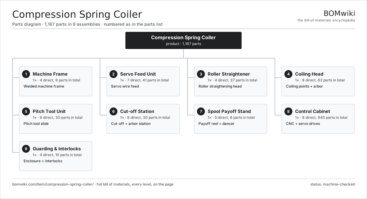
| # | Part | Qty | What it does |
|---|---|---|---|
| 1 | Machine Frame 4 parts | 1× | Welded machine frame |
| 2 | Servo Feed Unit 7 parts | 1× | Servo wire feed |
| 3 | Roller Straightener 4 parts | 1× | Roller straightening head |
| 4 | Coiling Head 8 parts | 1× | Coiling points + arbor |
| 5 | Pitch Tool Unit 6 parts | 1× | Pitch tool slide |
| 6 | Cut-off Station 6 parts | 1× | Cut-off + arbor station |
| 7 | Spool Payoff Stand 5 parts | 1× | Payoff reel + dancer |
| 8 | Control Cabinet 8 parts | 1× | CNC + servo drives |
| 9 | Guarding & Interlocks 4 parts | 1× | Enclosure + interlocks |
3D model
No 3D model yet. Have a CAD file of this? Add a 3D model — STL renders right on this page; STEP, FreeCAD, and OpenSCAD sources are welcome too (openly licensed, like all 3D models on BOMwiki).
Build & assembly graph
expand / collapse · shared sub-assemblies converge · links to related products · est. labourTap an assembly to expand/collapse · tap a part to open it · use “Open page” for any node · drag to pan, scroll to zoom.
Bill of materials for Compression Spring Coiler
9 top-level lines · 92 rows shown · 1,167 parts total · indented to 3 levels| # | Item / sub-assembly | Part no. | Qty/assy | Ext. qty | Parts | Type |
|---|---|---|---|---|---|---|
| 1 | Machine Frame 4 parts | compression-spring-coiler-frame | 1× | 1 | 9 | assembly |
| 1.1 | Base Weldment | compression-spring-coiler-base-weldment | 1× | 1 | · | part |
| 1.2 | Front Faceplate | compression-spring-coiler-faceplate | 1× | 1 | · | part |
| 1.3 | Leveling Foot | compression-spring-coiler-leveling-foot | 6× | 6 | · | part |
| 1.4 | Fastener Set | fastener-set | 1× | 1 | · | part |
| 2 | Servo Feed Unit 7 parts | compression-spring-coiler-feed-unit | 1× | 1 | 41 | assembly |
| 2.1 | Servo Motor 4 parts | servo-motor | 1× | 1 | 24 | assembly |
| 2.1.1 | Stator Assembly 3 parts + deeper › | stator-assembly | 1× | 1 | 3 | assembly |
| 2.1.2 | Rotor Assembly 4 parts + deeper › | rotor-assembly | 1× | 1 | 19 | assembly |
| 2.1.3 | Encoder | encoder | 1× | 1 | · | part |
| 2.1.4 | Motor Housing | motor-housing | 1× | 1 | · | part |
| 2.2 | Helical Gear Pair | gear-pair | 1× | 1 | · | part |
| 2.3 | Feed Roller | compression-spring-coiler-feed-roller | 4× | 4 | · | part |
| 2.4 | Roller Bracket | compression-spring-coiler-roller-bracket | 2× | 2 | · | part |
| 2.5 | Wire Entry Guide | compression-spring-coiler-feed-guide | 1× | 1 | · | part |
| 2.6 | Ball Bearing | ball-bearing | 8× | 8 | · | part |
| 2.7 | Encoder | encoder | 1× | 1 | · | part |
| 3 | Roller Straightener 4 parts | compression-spring-coiler-straightener | 1× | 1 | 37 | assembly |
| 3.1 | Straightening Roller | compression-spring-coiler-straighten-roller | 14× | 14 | · | part |
| 3.2 | Roller Carrier Block | compression-spring-coiler-straighten-block | 2× | 2 | · | part |
| 3.3 | Roller Adjust Screw | compression-spring-coiler-adjust-screw | 7× | 7 | · | part |
| 3.4 | Ball Bearing | ball-bearing | 14× | 14 | · | part |
| 4 | Coiling Head 8 parts | compression-spring-coiler-coiling-head | 1× | 1 | 62 | assembly |
| 4.1 | Coiling Point | compression-spring-coiler-coiling-point | 2× | 2 | · | part |
| 4.2 | Coiling Point Slide | compression-spring-coiler-point-slide | 2× | 2 | · | part |
| 4.3 | Coiling Arbor | compression-spring-coiler-arbor | 1× | 1 | · | part |
| 4.4 | Wire Guide Block | compression-spring-coiler-wire-guide | 1× | 1 | · | part |
| 4.5 | Servo Motor 4 parts | servo-motor | 2× | 2 | 24 | assembly |
| 4.5.1 | Stator Assembly 3 parts + deeper › | stator-assembly | 1× | 2 | 3 | assembly |
| 4.5.2 | Rotor Assembly 4 parts + deeper › | rotor-assembly | 1× | 2 | 19 | assembly |
| 4.5.3 | Encoder | encoder | 1× | 2 | · | part |
| 4.5.4 | Motor Housing | motor-housing | 1× | 2 | · | part |
| 4.6 | Linear Guide Rail | linear-guide | 2× | 2 | · | part |
| 4.7 | Ball Screw | ball-screw | 2× | 2 | · | part |
| 4.8 | Ball Bearing | ball-bearing | 4× | 4 | · | part |
| 5 | Pitch Tool Unit 6 parts | compression-spring-coiler-pitch-unit | 1× | 1 | 30 | assembly |
| 5.1 | Pitch Tool | compression-spring-coiler-pitch-tool | 1× | 1 | · | part |
| 5.2 | Pitch Slide | compression-spring-coiler-pitch-slide | 1× | 1 | · | part |
| 5.3 | Servo Motor 4 parts | servo-motor | 1× | 1 | 24 | assembly |
| 5.3.1 | Stator Assembly 3 parts + deeper › | stator-assembly | 1× | 1 | 3 | assembly |
| 5.3.2 | Rotor Assembly 4 parts + deeper › | rotor-assembly | 1× | 1 | 19 | assembly |
| 5.3.3 | Encoder | encoder | 1× | 1 | · | part |
| 5.3.4 | Motor Housing | motor-housing | 1× | 1 | · | part |
| 5.4 | Linear Guide Rail | linear-guide | 1× | 1 | · | part |
| 5.5 | Ball Screw | ball-screw | 1× | 1 | · | part |
| 5.6 | Ball Bearing | ball-bearing | 2× | 2 | · | part |
| 6 | Cut-off Station 6 parts | compression-spring-coiler-cutoff-unit | 1× | 1 | 30 | assembly |
| 6.1 | Cut-off Blade | compression-spring-coiler-cutoff-blade | 1× | 1 | · | part |
| 6.2 | Cut-off Slide | compression-spring-coiler-cutoff-slide | 1× | 1 | · | part |
| 6.3 | Cut-off Arbor Anvil | compression-spring-coiler-cut-arbor | 1× | 1 | · | part |
| 6.4 | Servo Motor 4 parts | servo-motor | 1× | 1 | 24 | assembly |
| 6.4.1 | Stator Assembly 3 parts + deeper › | stator-assembly | 1× | 1 | 3 | assembly |
| 6.4.2 | Rotor Assembly 4 parts + deeper › | rotor-assembly | 1× | 1 | 19 | assembly |
| 6.4.3 | Encoder | encoder | 1× | 1 | · | part |
| 6.4.4 | Motor Housing | motor-housing | 1× | 1 | · | part |
| 6.5 | Pneumatic Cylinder | pneumatic-cylinder | 1× | 1 | · | part |
| 6.6 | Ball Bearing | ball-bearing | 2× | 2 | · | part |
| 7 | Spool Payoff Stand 5 parts | compression-spring-coiler-spool-stand | 1× | 1 | 8 | assembly |
| 7.1 | Payoff Reel | compression-spring-coiler-payoff-reel | 1× | 1 | · | part |
| 7.2 | Dancer Arm | compression-spring-coiler-dancer-arm | 1× | 1 | · | part |
| 7.3 | Reel Drag Brake | compression-spring-coiler-reel-brake | 1× | 1 | · | part |
| 7.4 | Ball Bearing | ball-bearing | 4× | 4 | · | part |
| 7.5 | Coil Spring | coil-spring | 1× | 1 | · | part |
| 8 | Control Cabinet 8 parts | compression-spring-coiler-control-cabinet | 1× | 1 | 940 | assembly |
| 8.1 | Motion Controller 4 parts | compression-spring-coiler-cnc | 1× | 1 | 233 | assembly |
| 8.1.1 | Bare PCB | pcb-bare | 1× | 1 | · | part |
| 8.1.2 | Microcontroller | mcu | 2× | 2 | · | part |
| 8.1.3 | SMD Passive (R/C/L) | smd-passives | 200× | 200 | · | part |
| 8.1.4 | Connector | connector | 30× | 30 | · | part |
| 8.2 | Servo Drive 4 parts | servo-drive | 6× | 6 | 91 | assembly |
| 8.2.1 | Bare PCB | pcb-bare | 1× | 6 | · | part |
| 8.2.2 | IGBT Power Module | igbt-module | 1× | 6 | · | part |
| 8.2.3 | Gate Driver Board 3 parts + deeper › | gate-driver-board | 1× | 6 | 87 | assembly |
| 8.2.4 | DC-Link Capacitor | dc-link-cap | 2× | 12 | · | part |
| 8.3 | Power Supply | power-supply | 1× | 1 | · | part |
| 8.4 | Touchscreen HMI 4 parts | compression-spring-coiler-hmi | 1× | 1 | 83 | assembly |
| 8.4.1 | LCD Panel | lcd-panel | 1× | 1 | · | part |
| 8.4.2 | Touch Digitizer | touch-digitizer | 1× | 1 | · | part |
| 8.4.3 | Bare PCB | pcb-bare | 1× | 1 | · | part |
| 8.4.4 | SMD Passive (R/C/L) | smd-passives | 80× | 80 | · | part |
| 8.5 | I/O Module 3 parts | compression-spring-coiler-io-module | 2× | 2 | 33 | assembly |
| 8.5.1 | Bare PCB | pcb-bare | 1× | 2 | · | part |
| 8.5.2 | Relay | relay | 8× | 16 | · | part |
| 8.5.3 | Connector | connector | 24× | 48 | · | part |
| 8.6 | Relay | relay | 6× | 6 | · | part |
| 8.7 | Wire Bundle | wire-bundle | 1× | 1 | · | part |
| 8.8 | Sheet Metal Panel | sheet-panel | 4× | 4 | · | part |
| 9 | Guarding & Interlocks 4 parts | compression-spring-coiler-guarding | 1× | 1 | 10 | assembly |
| 9.1 | Sheet Metal Panel | sheet-panel | 4× | 4 | · | part |
| 9.2 | Polycarbonate Window | window-polycarbonate | 2× | 2 | · | part |
| 9.3 | Door Interlock Switch | compression-spring-coiler-door-interlock | 2× | 2 | · | part |
| 9.4 | Emergency Stop Button | compression-spring-coiler-estop | 2× | 2 | · | part |
Related products
same domain, ranked by shared parts Torsion Spring Coiler
1,148 parts · shares 15 with this page
Bar Chamfering Machine
1,148 parts · shares 14 with this page
Torsion Spring Coiler
1,148 parts · shares 15 with this page
Bar Chamfering Machine
1,148 parts · shares 14 with this page
 CNC Milling Machine
400 parts · shares 11 with this page
Spring End Grinding Machine
1,048 parts · shares 13 with this page
CNC Milling Machine
400 parts · shares 11 with this page
Spring End Grinding Machine
1,048 parts · shares 13 with this page
Sourcing: possible vendors
Prices, MOQ, and lead times are algorithmic estimates, not quotes, and not claims about these companies. Company mappings are curated by keyword; est. price band $10k–$1M. How estimates work| Vendor | HQ | Specialty | MOQ | Lead time |
|---|---|---|---|---|
|
🇩🇪DMG MORI
dmgmori.com ↗
|
Bielefeld, DE | Machine tools | 5 units | 12–20 wks |
|
🇯🇵Mazak
mazak.com ↗
|
Oguchi, JP | Machine tools | 5 units | 12–20 wks |
| haascnc.com ↗ | Oxnard, US | CNC machine tools | 5 units | 12–20 wks |
|
🇯🇵Okuma
okuma.com ↗
|
Niwa, JP | Machine tools | 5 units | 12–20 wks |
|
🇩🇪Trumpf
trumpf.com ↗
|
Ditzingen, DE | Laser & sheet-metal machines | 5 units | 12–20 wks |
985-word article