Deep-Hole Drilling Machine
ProductOverview
A deep-hole drilling machine produces holes that are far longer than they are wide, the kind ordinary twist drills cannot make. A conventional drill wanders and clogs once a hole passes about five times its diameter; a deep-hole machine reaches depth-to-diameter ratios of 50:1, 100:1, or more while holding the hole straight to a fraction of a millimetre per metre. It does this with special single-edge tooling, very high coolant pressure to flush chips, and a rigid machine that keeps the long tool from whipping. These machines bore gun barrels, hydraulic cylinders, injection-mould cooling channels, crankshaft oil galleries, turbine shafts, and medical implant tubes.
Two tooling families dominate. Gun drilling uses a single-flute tube with coolant fed down the centre and chips flushed back along an external V-groove; it suits smaller diameters and the deepest ratios. BTA drilling (boring and trepanning association) feeds coolant around the outside of the tube and ejects chips back through the tube bore; it suits larger diameters and removes metal faster. The machine described here supports both.
Machine bed and feed
The work rides on the Machine Bed, a long and very stiff Bed Casting that may run several metres. Straightness of the bed translates directly into straightness of the hole, so the bed carries precision guideways using the shared Linear Guide Rail leaf and a Ball Screw feed. A Coolant Trough runs the length of the bed to return the large volume of coolant to the tank. The carriage is fed slowly and steadily, because deep-hole drilling rewards a constant, vibration-free feed rate.
Headstock and workpiece rotation
The Workpiece Headstock holds the workpiece in a Hydraulic Chuck on a bored Work Spindle running on bearings from the shared Ball Bearing leaf, driven by the Spindle Motor through a Helical Gear Pair. Hole straightness depends heavily on relative rotation between tool and work. The best results come from counter-rotation, the work turning one way and the drill the other, because any tendency of the tool to drift averages out as both spin. Large or non-round work is held fixed while only the tool rotates.
Drill carriage and tooling
The cutting motion comes from the Drill Spindle Carriage carriage. A Carriage Saddle saddle carries the Drill Spindle driven by the Drill Motor, and the Feed Motor, built on the shared Servo Motor leaf, advances it along the bed. The tool itself is the Drill Tube & Boring Bar: a long Drill Tube tipped with a carbide Cutting Head and fitted with Guide Pad. The single cutting edge pushes the tool sideways against the guide pads, which burnish the bore wall and hold the head centred, and this self-guiding action is what keeps a deep hole straight. The tube joins the spindle through a Tube Coupling.
High-pressure coolant
Coolant is not a luxury here, it is the mechanism that makes deep drilling possible. The High-Pressure Coolant system uses a High-Pressure Pump delivering 20-120 bar to drive cutting fluid through the tool, cool the cutting edge, and carry every chip out of the hole. Because a single chip left in a deep hole can jam and snap the tool, the coolant must stay clean and cool: a Coolant Filter removes fines to 10-25 microns, a Coolant Chiller holds the oil temperature steady so the hole does not grow as it heats, and Pressure Sensor units watch the flow. The fluid is stored in a large Coolant Tank.
Chip separation
The returning coolant carries a continuous stream of chips that must be removed before the fluid is pumped back. The Chip Separation System catches them in a Chip Box at the pressure head, screens them on a Vibrating Screen, pulls ferrous fines out with a Magnetic Separator, and carries the solids away on a Chip Conveyor. Reliable chip separation is what lets the machine run for hours unattended.
Pressure head and whip control
At the bore entry the Pressure Head & Whip Guides does two jobs. A Pressure Seal contains the high-pressure coolant at the hole mouth so it does not spray everywhere, and a Drill Bush Block starts the hole exactly true, since the first few millimetres set the direction of the whole bore. Because the drill tube can be several metres long and spins fast, Whip Guide guides close around it to suppress whip and open as the carriage passes, while Steady Rest rests support long workpieces.
Control and use
The CNC Control is a CNC built on a CNC Computer computer, a Drive Cabinet, and a Operator Panel. Beyond positioning, the control watches drilling power and coolant pressure so it can detect a clogging hole or a breaking tool and retract before the tool snaps deep in an expensive workpiece. In service the machine holds straightness of 0.1-0.5 mm per metre and a bore finish of 0.4-1.6 micron, accuracy that would be impossible with conventional drilling, which is why deep-hole machines are dedicated equipment in firearms, hydraulics, mould-making, and aerospace shafting.
Deep-Hole Drilling Machine parts and their functions
8 top-level parts · 418 parts in total · full bill of materials below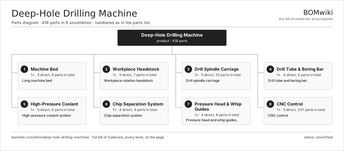
| # | Part | Qty | What it does |
|---|---|---|---|
| 1 | Machine Bed 5 parts | 1× | Long machine bed |
| 2 | Workpiece Headstock 5 parts | 1× | Workpiece rotation headstock |
| 3 | Drill Spindle Carriage 5 parts | 1× | Drill spindle carriage |
| 4 | Drill Tube & Boring Bar 4 parts | 1× | Drill tube and boring bar |
| 5 | High-Pressure Coolant 5 parts | 1× | High-pressure coolant system |
| 6 | Chip Separation System 4 parts | 1× | Chip separation system |
| 7 | Pressure Head & Whip Guides 4 parts | 1× | Pressure head and whip guides |
| 8 | CNC Control 5 parts | 1× | CNC control |
3D model
No 3D model yet. Have a CAD file of this? Add a 3D model — STL renders right on this page; STEP, FreeCAD, and OpenSCAD sources are welcome too (openly licensed, like all 3D models on BOMwiki).
Build & assembly graph
expand / collapse · shared sub-assemblies converge · links to related products · est. labourTap an assembly to expand/collapse · tap a part to open it · use “Open page” for any node · drag to pan, scroll to zoom.
Bill of materials for Deep-Hole Drilling Machine
8 top-level lines · 56 rows shown · 418 parts total · indented to 3 levels| # | Item / sub-assembly | Part no. | Qty/assy | Ext. qty | Parts | Type |
|---|---|---|---|---|---|---|
| 1 | Machine Bed 5 parts | deep-hole-drilling-machine-bed | 1× | 1 | 8 | assembly |
| 1.1 | Bed Casting | deep-hole-drilling-machine-bed-casting | 1× | 1 | · | part |
| 1.2 | Linear Guide Rail | linear-guide | 4× | 4 | · | part |
| 1.3 | Ball Screw | ball-screw | 1× | 1 | · | part |
| 1.4 | Coolant Trough | deep-hole-drilling-machine-bed-trough | 1× | 1 | · | part |
| 1.5 | Fastener Set | fastener-set | 1× | 1 | · | part |
| 2 | Workpiece Headstock 5 parts | deep-hole-drilling-machine-headstock | 1× | 1 | 7 | assembly |
| 2.1 | Work Spindle | deep-hole-drilling-machine-work-spindle | 1× | 1 | · | part |
| 2.2 | Hydraulic Chuck | deep-hole-drilling-machine-chuck | 1× | 1 | · | part |
| 2.3 | Spindle Motor | deep-hole-drilling-machine-spindle-motor | 1× | 1 | · | part |
| 2.4 | Ball Bearing | ball-bearing | 3× | 3 | · | part |
| 2.5 | Helical Gear Pair | gear-pair | 1× | 1 | · | part |
| 3 | Drill Spindle Carriage 5 parts | deep-hole-drilling-machine-drill-head | 1× | 1 | 32 | assembly |
| 3.1 | Carriage Saddle | deep-hole-drilling-machine-carriage | 1× | 1 | · | part |
| 3.2 | Drill Spindle | deep-hole-drilling-machine-drill-spindle | 1× | 1 | · | part |
| 3.3 | Drill Motor | deep-hole-drilling-machine-drill-motor | 1× | 1 | · | part |
| 3.4 | Feed Motor 2 parts | deep-hole-drilling-machine-feed-motor | 1× | 1 | 25 | assembly |
| 3.4.1 | Servo Motor 4 parts + deeper › | servo-motor | 1× | 1 | 24 | assembly |
| 3.4.2 | Ball Bearing | ball-bearing | 1× | 1 | · | part |
| 3.5 | Ball Bearing | ball-bearing | 4× | 4 | · | part |
| 4 | Drill Tube & Boring Bar 4 parts | deep-hole-drilling-machine-tool-system | 1× | 1 | 6 | assembly |
| 4.1 | Drill Tube | deep-hole-drilling-machine-drill-tube | 1× | 1 | · | part |
| 4.2 | Cutting Head | deep-hole-drilling-machine-cutting-head | 1× | 1 | · | part |
| 4.3 | Guide Pad | deep-hole-drilling-machine-guide-pads | 3× | 3 | · | part |
| 4.4 | Tube Coupling | deep-hole-drilling-machine-tube-coupling | 1× | 1 | · | part |
| 5 | High-Pressure Coolant 5 parts | deep-hole-drilling-machine-coolant | 1× | 1 | 6 | assembly |
| 5.1 | High-Pressure Pump | deep-hole-drilling-machine-hp-pump | 1× | 1 | · | part |
| 5.2 | Coolant Tank | deep-hole-drilling-machine-coolant-tank | 1× | 1 | · | part |
| 5.3 | Coolant Filter | deep-hole-drilling-machine-filter | 1× | 1 | · | part |
| 5.4 | Coolant Chiller | deep-hole-drilling-machine-chiller | 1× | 1 | · | part |
| 5.5 | Pressure Sensor | pressure-sensor | 2× | 2 | · | part |
| 6 | Chip Separation System 4 parts | deep-hole-drilling-machine-chip-system | 1× | 1 | 4 | assembly |
| 6.1 | Chip Box | deep-hole-drilling-machine-chip-box | 1× | 1 | · | part |
| 6.2 | Chip Conveyor | deep-hole-drilling-machine-conveyor | 1× | 1 | · | part |
| 6.3 | Magnetic Separator | deep-hole-drilling-machine-magnetic-sep | 1× | 1 | · | part |
| 6.4 | Vibrating Screen | deep-hole-drilling-machine-screen | 1× | 1 | · | part |
| 7 | Pressure Head & Whip Guides 4 parts | deep-hole-drilling-machine-pressure-head | 1× | 1 | 8 | assembly |
| 7.1 | Pressure Seal | deep-hole-drilling-machine-pressure-seal | 1× | 1 | · | part |
| 7.2 | Drill Bush Block | deep-hole-drilling-machine-bush-block | 1× | 1 | · | part |
| 7.3 | Whip Guide | deep-hole-drilling-machine-whip-guide | 4× | 4 | · | part |
| 7.4 | Steady Rest | deep-hole-drilling-machine-steady-rest | 2× | 2 | · | part |
| 8 | CNC Control 5 parts | deep-hole-drilling-machine-control | 1× | 1 | 347 | assembly |
| 8.1 | CNC Computer 3 parts | deep-hole-drilling-machine-cnc | 1× | 1 | 153 | assembly |
| 8.1.1 | Bare PCB | pcb-bare | 1× | 1 | · | part |
| 8.1.2 | Microcontroller | mcu | 2× | 2 | · | part |
| 8.1.3 | SMD Passive (R/C/L) | smd-passives | 150× | 150 | · | part |
| 8.2 | Drive Cabinet 3 parts | deep-hole-drilling-machine-drive-cabinet | 1× | 1 | 130 | assembly |
| 8.2.1 | Bare PCB | pcb-bare | 2× | 2 | · | part |
| 8.2.2 | Relay | relay | 8× | 8 | · | part |
| 8.2.3 | SMD Passive (R/C/L) | smd-passives | 120× | 120 | · | part |
| 8.3 | Operator Panel 3 parts | deep-hole-drilling-machine-operator-panel | 1× | 1 | 62 | assembly |
| 8.3.1 | LCD Panel | lcd-panel | 1× | 1 | · | part |
| 8.3.2 | Bare PCB | pcb-bare | 1× | 1 | · | part |
| 8.3.3 | SMD Passive (R/C/L) | smd-passives | 60× | 60 | · | part |
| 8.4 | Power Supply | power-supply | 1× | 1 | · | part |
| 8.5 | Wire Bundle | wire-bundle | 1× | 1 | · | part |
Related products
same domain, ranked by shared parts Bevel Gear Generator
201 parts · shares 5 with this page
Centering and Facing Machine
1,419 parts · shares 5 with this page
CNC Wire Forming Machine
1,438 parts · shares 5 with this page
Bevel Gear Generator
201 parts · shares 5 with this page
Centering and Facing Machine
1,419 parts · shares 5 with this page
CNC Wire Forming Machine
1,438 parts · shares 5 with this page
 Compression Spring Coiler
1,167 parts · shares 5 with this page
Compression Spring Coiler
1,167 parts · shares 5 with this page
 Crankshaft Grinder
511 parts · shares 5 with this page
Crankshaft Grinder
511 parts · shares 5 with this page
Sourcing: possible vendors
Prices, MOQ, and lead times are algorithmic estimates, not quotes, and not claims about these companies. Company mappings are curated by keyword; est. price band $10k–$1M. How estimates work| Vendor | HQ | Specialty | MOQ | Lead time |
|---|---|---|---|---|
|
🇩🇪DMG MORI
dmgmori.com ↗
|
Bielefeld, DE | Machine tools | 5 units | 12–20 wks |
|
🇯🇵Mazak
mazak.com ↗
|
Oguchi, JP | Machine tools | 5 units | 12–20 wks |
| haascnc.com ↗ | Oxnard, US | CNC machine tools | 5 units | 12–20 wks |
|
🇯🇵Okuma
okuma.com ↗
|
Niwa, JP | Machine tools | 5 units | 12–20 wks |
|
🇩🇪Trumpf
trumpf.com ↗
|
Ditzingen, DE | Laser & sheet-metal machines | 5 units | 12–20 wks |
975-word article