Multi-Spindle Drilling Head
ProductOverview
A multi-spindle drilling head is an attachment that turns a single rotating spindle into many. It bolts onto an ordinary drill press, a milling machine, or a transfer-line station, takes drive from one input, and distributes that drive through gears to a bank of output spindles, each holding its own drill. When the host machine feeds the head down, every spindle drills at once, so a pattern of holes that would take many separate operations is produced in a single pass. A head with twelve spindles drills twelve holes in the time it takes to drill one, which is why these heads are a standard way to raise output on bolt-circle flanges, valve plates, engine blocks, and electronics chassis.
The head is not a complete machine; it is a gearbox that multiplies spindles. The host machine supplies the rotation, the feed, and the workholding, while the head fixes the hole pattern and divides the power. This keeps it affordable and lets one drill press serve many jobs by swapping heads.
Gearbox body
Everything is contained in the Gearbox Body. A Main Housing of cast iron or aluminium encloses the gear train, with a Front Spindle Plate front plate bored to carry the output spindle bearings and a Rear Cover for gear access. The joints are sealed with the shared O-Ring Set leaf because the gears run in an oil bath. The body has to be stiff: drilling thrust is multiplied by the number of spindles, and any flex would throw off the hole positions.
Input drive and gear distribution
Drive enters through the Input Drive assembly. The Input Shaft couples to the host spindle, runs on bearings from the shared Ball Bearing leaf, and is sealed by the shared Oil Seal. It carries a central Input Gear that meshes into the Gear Distribution Train. The train uses a ring of Idler Gear idlers on Idler Shaft shafts to carry rotation outward to every spindle, and a Cluster Gear sets the overall speed ratio so the drills turn at a useful speed regardless of the host spindle speed. Gear quality matters here because all the spindles must turn smoothly together without the train binding or whining.
Output spindle bank
The working end is the Output Spindle Bank. Each Output Spindle runs in its own pair of bearings, is driven by a Spindle Pinion pinion, and grips a drill in a Tool Collet. The number of spindles ranges from two to fifty. The closest the spindles can be packed is limited by the diameter of the spindle gears, which sets the minimum hole spacing on a fixed-centre head, typically 12-25 mm.
Fixed-centre versus adjustable heads
There are two families of head. A fixed-centre head has its spindles permanently positioned for one hole pattern, which makes it simple, rigid, and accurate, but dedicated to a single part. A universal head adds the Adjustable Spindle Template feature so the same head can drill many patterns. Here each drill is driven through a Spindle Extension fitted with two Universal Joint universal joints, so the drill end can be moved away from the fixed spindle to wherever the hole sits. A Locator Plate drilled to the part pattern fixes the drill positions, and a Clamp Bush locks each one in place. The universal type trades some rigidity and minimum spacing for the ability to handle a different hole pattern by changing only the locator plate.
Lubrication
Because the gear train runs continuously and carries the full drilling load, the Lubrication System system keeps it cool and protected. Larger heads use an Oil Pump feeding oil through a Oil Gallery to the bearings, with a Sight Glass showing the level and the shared Oil Seal leaf keeping oil off the work. Smaller heads simply splash oil from a bath.
Mounting and use
The head attaches to its host through the Mounting Plate. An Adapter Plate matches the machine quill or table, Alignment Dowel pins set the alignment, and an Anti-Torque Arm arm reacts the combined drilling torque back to the machine column so the head cannot twist. In use the operator clamps a part, lowers the head with the host machine feed, and all holes are drilled together; spindles can also be loaded with different tools, for example drills and counterbores, to finish a hole pattern in one stroke. The main payoff is throughput: cycle time drops in proportion to the number of spindles, while hole position accuracy is held by the gear centres or the locator plate rather than by the operator.
Multi-Spindle Drilling Head parts and their functions
7 top-level parts · 157 parts in total · full bill of materials below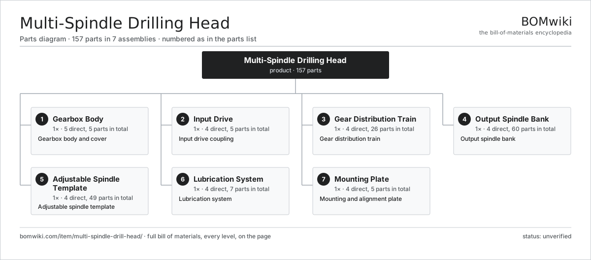
| # | Part | Qty | What it does |
|---|---|---|---|
| 1 | Gearbox Body 5 parts | 1× | Gearbox body and cover |
| 2 | Input Drive 4 parts | 1× | Input drive coupling |
| 3 | Gear Distribution Train 4 parts | 1× | Gear distribution train |
| 4 | Output Spindle Bank 4 parts | 1× | Output spindle bank |
| 5 | Adjustable Spindle Template 4 parts | 1× | Adjustable spindle template |
| 6 | Lubrication System 4 parts | 1× | Lubrication system |
| 7 | Mounting Plate 4 parts | 1× | Mounting and alignment plate |
3D model
No 3D model yet. Have a CAD file of this? Add a 3D model — STL renders right on this page; STEP, FreeCAD, and OpenSCAD sources are welcome too (openly licensed, like all 3D models on BOMwiki).
Build & assembly graph
expand / collapse · shared sub-assemblies converge · links to related products · est. labourTap an assembly to expand/collapse · tap a part to open it · use “Open page” for any node · drag to pan, scroll to zoom.
Bill of materials for Multi-Spindle Drilling Head
7 top-level lines · 36 rows shown · 157 parts total · indented to 3 levels| # | Item / sub-assembly | Part no. | Qty/assy | Ext. qty | Parts | Type |
|---|---|---|---|---|---|---|
| 1 | Gearbox Body 5 parts | multi-spindle-drill-head-body | 1× | 1 | 5 | assembly |
| 1.1 | Main Housing | multi-spindle-drill-head-housing | 1× | 1 | · | part |
| 1.2 | Front Spindle Plate | multi-spindle-drill-head-cover | 1× | 1 | · | part |
| 1.3 | Rear Cover | multi-spindle-drill-head-back-cover | 1× | 1 | · | part |
| 1.4 | O-Ring Set | oring-set | 1× | 1 | · | part |
| 1.5 | Fastener Set | fastener-set | 1× | 1 | · | part |
| 2 | Input Drive 4 parts | multi-spindle-drill-head-input | 1× | 1 | 5 | assembly |
| 2.1 | Input Shaft | multi-spindle-drill-head-input-shaft | 1× | 1 | · | part |
| 2.2 | Input Gear | multi-spindle-drill-head-input-gear | 1× | 1 | · | part |
| 2.3 | Ball Bearing | ball-bearing | 2× | 2 | · | part |
| 2.4 | Oil Seal | oil-seal | 1× | 1 | · | part |
| 3 | Gear Distribution Train 4 parts | multi-spindle-drill-head-gear-train | 1× | 1 | 26 | assembly |
| 3.1 | Idler Gear | multi-spindle-drill-head-idler-gear | 6× | 6 | · | part |
| 3.2 | Idler Shaft | multi-spindle-drill-head-idler-shaft | 6× | 6 | · | part |
| 3.3 | Cluster Gear | multi-spindle-drill-head-cluster-gear | 2× | 2 | · | part |
| 3.4 | Ball Bearing | ball-bearing | 12× | 12 | · | part |
| 4 | Output Spindle Bank 4 parts | multi-spindle-drill-head-spindle-bank | 1× | 1 | 60 | assembly |
| 4.1 | Output Spindle | multi-spindle-drill-head-spindle | 12× | 12 | · | part |
| 4.2 | Spindle Pinion | multi-spindle-drill-head-spindle-gear | 12× | 12 | · | part |
| 4.3 | Tool Collet | multi-spindle-drill-head-collet | 12× | 12 | · | part |
| 4.4 | Ball Bearing | ball-bearing | 24× | 24 | · | part |
| 5 | Adjustable Spindle Template 4 parts | multi-spindle-drill-head-template | 1× | 1 | 49 | assembly |
| 5.1 | Spindle Extension | multi-spindle-drill-head-extension | 12× | 12 | · | part |
| 5.2 | Universal Joint | multi-spindle-drill-head-uni-joint | 24× | 24 | · | part |
| 5.3 | Locator Plate | multi-spindle-drill-head-locator-plate | 1× | 1 | · | part |
| 5.4 | Clamp Bush | multi-spindle-drill-head-clamp-bush | 12× | 12 | · | part |
| 6 | Lubrication System 4 parts | multi-spindle-drill-head-lube | 1× | 1 | 7 | assembly |
| 6.1 | Oil Pump | multi-spindle-drill-head-oil-pump | 1× | 1 | · | part |
| 6.2 | Oil Gallery | multi-spindle-drill-head-oil-gallery | 1× | 1 | · | part |
| 6.3 | Sight Glass | multi-spindle-drill-head-sight-glass | 1× | 1 | · | part |
| 6.4 | Oil Seal | oil-seal | 4× | 4 | · | part |
| 7 | Mounting Plate 4 parts | multi-spindle-drill-head-mount | 1× | 1 | 5 | assembly |
| 7.1 | Adapter Plate | multi-spindle-drill-head-adapter-plate | 1× | 1 | · | part |
| 7.2 | Alignment Dowel | multi-spindle-drill-head-dowel | 2× | 2 | · | part |
| 7.3 | Anti-Torque Arm | multi-spindle-drill-head-anti-torque | 1× | 1 | · | part |
| 7.4 | Fastener Set | fastener-set | 1× | 1 | · | part |
Related products
same domain, ranked by shared parts Abrasive Flow Machining Machine
279 parts · shares 1 with this page
Abrasive Flow Machining Machine
279 parts · shares 1 with this page
 Aluminum Extrusion Press
365 parts · shares 1 with this page
Aluminum Extrusion Press
365 parts · shares 1 with this page
 Angle Roll Bender
100 parts · shares 1 with this page
Bar Chamfering Machine
1,148 parts · shares 1 with this page
Angle Roll Bender
100 parts · shares 1 with this page
Bar Chamfering Machine
1,148 parts · shares 1 with this page
 Bed-Type Milling Machine
151 parts · shares 1 with this page
Bed-Type Milling Machine
151 parts · shares 1 with this page
 Bevel Gear Generator
201 parts · shares 1 with this page
Bevel Gear Generator
201 parts · shares 1 with this page
Sourcing: possible vendors
Prices, MOQ, and lead times are algorithmic estimates, not quotes, and not claims about these companies. Company mappings are curated by keyword; est. price band $10k–$1M. How estimates work| Vendor | HQ | Specialty | MOQ | Lead time |
|---|---|---|---|---|
|
🇩🇪DMG MORI
dmgmori.com ↗
|
Bielefeld, DE | Machine tools | 5 units | 12–20 wks |
|
🇯🇵Mazak
mazak.com ↗
|
Oguchi, JP | Machine tools | 5 units | 12–20 wks |
| haascnc.com ↗ | Oxnard, US | CNC machine tools | 5 units | 12–20 wks |
|
🇯🇵Okuma
okuma.com ↗
|
Niwa, JP | Machine tools | 5 units | 12–20 wks |
|
🇩🇪Trumpf
trumpf.com ↗
|
Ditzingen, DE | Laser & sheet-metal machines | 5 units | 12–20 wks |
861-word article