Skin Pass Mill
ProductRole of the skin pass
A skin pass mill applies the final light pass to cold-rolled or coated steel strip. The reduction is small, typically 0.3% to 2.0% of permanent extension, and the goal is not gauge reduction but surface and shape. The pass does three jobs at once. It flattens the strip so it lies down after coiling, it transfers a controlled surface roughness from the Work Roll to the strip, and it works the surface layer enough to suppress yield-point elongation. Without that last effect, deep-drawn parts show Luders bands (stretcher strain marks) when the customer presses them. A single pass through the Skin Pass Mill removes that risk for several months of aging.
The unit is built around one rolling stand. That makes it look like a temper mill, and the rolling mechanics are the same, but the application differs. A skin pass mill usually sits inline inside a continuous annealing line or a hot-dip galvanizing line, after the furnace and coating sections, where it handles galvanized, galvannealed and electro-coated strip in addition to bare cold-rolled coil. Because it is inline, its speed is tied to the rest of the line, and the strip arrives already under tension from the line bridles and accumulators rather than from a payoff and coiler local to the stand.
Mill stand and housing
The Mill Stand & Housing carries the roll-separating force across the full strip width. Two cast Housing Post uprights are closed by a Housing Cap at the top and clamped together with pre-tensioned Tie Rod members so the stand stays stiff when force changes. Each post sits on a grouted Sole Plate. The window in which the roll chocks slide is faced with a replaceable Window Liner Plate and kept square by a Window Guide. Stand stiffness matters here more than in a heavy reduction mill: the elongation is so small that gauge and shape are sensitive to any spring in the housing.
Roll set and chocks
The Roll Set is the part that does the surface work. Two hardened Work Roll rolls contact the strip. Their finish, either electro-discharge texture (EDT) or a fine bright grind, is copied onto the strip surface in the bite, which is why work-roll roughness and the wear of that texture are tracked closely. Two large Back-Up Roll rolls sit behind the work rolls to resist bending and hold the gap flat across the width. Each roll neck runs in a Roll Chock. The back-up necks carry the highest load and run in a hydrodynamic Oil-Film Bearing, while the work-roll positions use Ball Bearing units for location and thrust. A Roll-Neck Seal and an Oil Seal keep water, solution and scale out of the bearings.
Roll-force and elongation control
Elongation control is the defining function of the mill. The Roll-Force & Elongation Control sets the small permanent extension by trimming roll force against measured strip tension and speed. A hydraulic Hydraulic Loading Cylinder on each side applies the force through a Servo Valve, a Roll-Gap Position Sensor reads the roll gap, and a Load Cell reads actual force per side. A Roll-Bending Cylinder set bends the work-roll necks to correct flatness across the width. The Elongation Controller computes percent extension from the entry and exit strip speed, then trims force and tension to hold the target. Because the strip is loaded both by roll force and by line tension, the controller treats the two together: at light elongation, more of the work can come from tension; at heavier settings, force dominates.
Strip tension, bridles and threading
The Strip Tension & Threading holds the strip under tension on both sides of the stand. A driven Entry Bridle sets back tension and a driven Exit Bridle sets forward tension, isolating the stand from coiler or downstream pull. A Deflector Roll steers the path, a Strip Centering Guide keeps the strip centered, and a Tensiometer Roll measures actual tension for the elongation loop. A Strip Speed Encoder on each side gives entry and exit speed; the ratio of the two is the measured elongation. A Strip Wiper clears residual liquid and debris before the strip leaves.
Drive, hydraulics and controls
The Drive Train turns the work rolls through a Main Drive Motor, a Gear Distributor that splits torque to top and bottom, two Drive Spindle members and a Drive Coupling at each end. Separate Bridle Drive Motor units drive the bridles. The Lubrication & Hydraulics group runs a circulating Lube Oil Unit for the bearings and a Hydraulic Power Unit for the loading and bending cylinders. The Control System coordinates roll force, elongation, roughness and line speed; it carries a Control Panel, a Drive Control Cabinet cabinet for line-speed coordination, a Roughness Monitor, plus Pressure Sensor and Load Cell inputs, a Wire Bundle, Relay outputs and redundant Power Supply units.
Wet skin-pass and variants
In wet mode the Wet Skin-Pass & Surface System meters a dilute solution into the bite from a Solution Tank through a Solution Pump, a Applicator Header and a row of Spray Nozzle jets. A Wringer / Squeegee Roll and a Blow-Off / Drying Header remove the liquid afterward, a Solution Filter keeps the loop clean, and a Roll-Cleaning Brush keeps the roll texture free of pickup. The wet pass gives a more uniform finish and reduces work-roll wear on long campaigns. Dry skin passing is used where a specific dry texture is wanted. The mill runs bare cold-rolled coil as well as galvanized and galvannealed strip, where the pass also flattens and smooths the zinc coating. Against a standalone temper mill, which is a dedicated batch stand with its own payoff and recoiler, this stand earns its keep by being inline: it picks up strip already conditioned by the furnace and coating sections and matches its speed to them.
Skin Pass Mill parts and their functions
8 top-level parts · 362 parts in total · full bill of materials below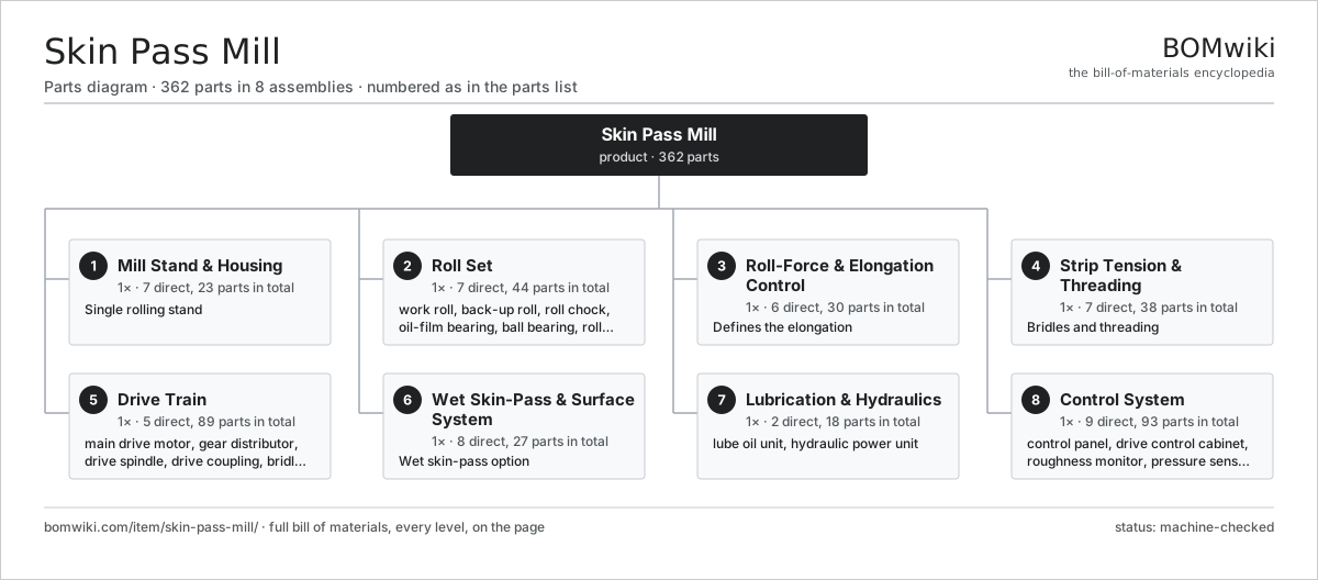
| # | Part | Qty | What it does |
|---|---|---|---|
| 1 | Mill Stand & Housing 7 parts | 1× | Single rolling stand |
| 2 | Roll Set 7 parts | 1× | Two textured work rolls backed by two large back-up rolls; the work-roll surface transfers roughness to the strip. |
| 3 | Roll-Force & Elongation Control 6 parts | 1× | Defines the elongation |
| 4 | Strip Tension & Threading 7 parts | 1× | Bridles and threading |
| 5 | Drive Train 5 parts | 1× | Main motor drives the work rolls through a gear distributor and spindles; separate motors drive the bridles. |
| 6 | Wet Skin-Pass & Surface System 8 parts | 1× | Wet skin-pass option |
| 7 | Lubrication & Hydraulics 2 parts | 1× | Circulating oil lubrication for the bearings plus the hydraulic power unit feeding the loading and bending cylinders. |
| 8 | Control System 9 parts | 1× | Coordinates roll force, elongation, roughness monitoring and line speed with the upstream and downstream sections. |
3D model
No 3D model yet. Have a CAD file of this? Add a 3D model — STL renders right on this page; STEP, FreeCAD, and OpenSCAD sources are welcome too (openly licensed, like all 3D models on BOMwiki).
Build & assembly graph
expand / collapse · shared sub-assemblies converge · links to related products · est. labourTap an assembly to expand/collapse · tap a part to open it · use “Open page” for any node · drag to pan, scroll to zoom.
Bill of materials for Skin Pass Mill
8 top-level lines · 111 rows shown · 362 parts total · indented to 3 levels| # | Item / sub-assembly | Part no. | Qty/assy | Ext. qty | Parts | Type |
|---|---|---|---|---|---|---|
| 1 | Mill Stand & Housing 7 parts | skin-pass-mill-stand | 1× | 1 | 23 | assembly |
| 1.1 | Housing Post | skin-pass-mill-housing-post | 2× | 2 | · | part |
| 1.2 | Housing Cap | skin-pass-mill-housing-cap | 2× | 2 | · | part |
| 1.3 | Tie Rod | skin-pass-mill-tie-rod | 4× | 4 | · | part |
| 1.4 | Sole Plate | skin-pass-mill-sole-plate | 2× | 2 | · | part |
| 1.5 | Window Liner Plate | skin-pass-mill-liner-plate | 8× | 8 | · | part |
| 1.6 | Window Guide | skin-pass-mill-window-guide | 4× | 4 | · | part |
| 1.7 | Fastener Set | fastener-set | 1× | 1 | · | part |
| 2 | Roll Set 7 parts | skin-pass-mill-roll-set | 1× | 1 | 44 | assembly |
| 2.1 | Work Roll | skin-pass-mill-work-roll | 2× | 2 | · | part |
| 2.2 | Back-Up Roll | skin-pass-mill-backup-roll | 2× | 2 | · | part |
| 2.3 | Roll Chock 3 parts | skin-pass-mill-roll-chock | 4× | 4 | 3 | assembly |
| 2.3.1 | Chock Body | skin-pass-mill-chock-body | 1× | 4 | · | part |
| 2.3.2 | Ball Bearing | ball-bearing | 1× | 4 | · | part |
| 2.3.3 | O-Ring Set | oring-set | 1× | 4 | · | part |
| 2.4 | Oil-Film Bearing 3 parts | skin-pass-mill-oilfilm-bearing | 4× | 4 | 3 | assembly |
| 2.4.1 | Bearing Sleeve | skin-pass-mill-bearing-sleeve | 1× | 4 | · | part |
| 2.4.2 | Bearing Bushing | skin-pass-mill-bearing-bushing | 1× | 4 | · | part |
| 2.4.3 | Oil Seal | oil-seal | 1× | 4 | · | part |
| 2.5 | Ball Bearing | ball-bearing | 4× | 4 | · | part |
| 2.6 | Roll-Neck Seal | skin-pass-mill-neck-seal | 8× | 8 | · | part |
| 2.7 | Oil Seal | oil-seal | 4× | 4 | · | part |
| 3 | Roll-Force & Elongation Control 6 parts | skin-pass-mill-rollforce-control | 1× | 1 | 30 | assembly |
| 3.1 | Hydraulic Loading Cylinder 4 parts | skin-pass-mill-loading-cylinder | 2× | 2 | 6 | assembly |
| 3.1.1 | Cylinder Barrel | skin-pass-mill-cylinder-barrel | 1× | 2 | · | part |
| 3.1.2 | Cylinder Piston | skin-pass-mill-cylinder-piston | 1× | 2 | · | part |
| 3.1.3 | O-Ring Set | oring-set | 2× | 4 | · | part |
| 3.1.4 | Oil Seal | oil-seal | 2× | 4 | · | part |
| 3.2 | Servo Valve | skin-pass-mill-servo-valve | 2× | 2 | · | part |
| 3.3 | Roll-Gap Position Sensor | skin-pass-mill-position-sensor | 2× | 2 | · | part |
| 3.4 | Load Cell | skin-pass-mill-load-cell | 2× | 2 | · | part |
| 3.5 | Roll-Bending Cylinder | skin-pass-mill-bending-cylinder | 4× | 4 | · | part |
| 3.6 | Elongation Controller 3 parts | skin-pass-mill-elongation-controller | 1× | 1 | 8 | assembly |
| 3.6.1 | Bare PCB | pcb-bare | 1× | 1 | · | part |
| 3.6.2 | Microcontroller | mcu | 1× | 1 | · | part |
| 3.6.3 | Connector | connector | 6× | 6 | · | part |
| 4 | Strip Tension & Threading 7 parts | skin-pass-mill-strip-line | 1× | 1 | 38 | assembly |
| 4.1 | Entry Bridle 3 parts | skin-pass-mill-entry-bridle | 1× | 1 | 13 | assembly |
| 4.1.1 | Bridle Roll | skin-pass-mill-bridle-roll | 4× | 4 | · | part |
| 4.1.2 | Ball Bearing | ball-bearing | 8× | 8 | · | part |
| 4.1.3 | Bridle Frame | skin-pass-mill-bridle-frame | 1× | 1 | · | part |
| 4.2 | Exit Bridle 3 parts | skin-pass-mill-exit-bridle | 1× | 1 | 13 | assembly |
| 4.2.1 | Bridle Roll | skin-pass-mill-bridle-roll | 4× | 4 | · | part |
| 4.2.2 | Ball Bearing | ball-bearing | 8× | 8 | · | part |
| 4.2.3 | Bridle Frame | skin-pass-mill-bridle-frame | 1× | 1 | · | part |
| 4.3 | Deflector Roll | skin-pass-mill-deflector-roll | 4× | 4 | · | part |
| 4.4 | Strip Centering Guide | skin-pass-mill-centering-guide | 2× | 2 | · | part |
| 4.5 | Tensiometer Roll | skin-pass-mill-tensiometer | 2× | 2 | · | part |
| 4.6 | Strip Speed Encoder | skin-pass-mill-speed-encoder | 2× | 2 | · | part |
| 4.7 | Strip Wiper | skin-pass-mill-strip-wiper | 2× | 2 | · | part |
| 5 | Drive Train 5 parts | skin-pass-mill-drive | 1× | 1 | 89 | assembly |
| 5.1 | Main Drive Motor 5 parts | skin-pass-mill-main-motor | 1× | 1 | 26 | assembly |
| 5.1.1 | Stator Assembly 3 parts + deeper › | stator-assembly | 1× | 1 | 3 | assembly |
| 5.1.2 | Rotor Assembly 4 parts + deeper › | rotor-assembly | 1× | 1 | 19 | assembly |
| 5.1.3 | Copper Winding | copper-winding | 1× | 1 | · | part |
| 5.1.4 | Motor Housing | motor-housing | 1× | 1 | · | part |
| 5.1.5 | Ball Bearing | ball-bearing | 2× | 2 | · | part |
| 5.2 | Gear Distributor 4 parts | skin-pass-mill-gear-distributor | 1× | 1 | 9 | assembly |
| 5.2.1 | Helical Gear Pair | gear-pair | 2× | 2 | · | part |
| 5.2.2 | Gearbox Housing | gearbox-housing | 1× | 1 | · | part |
| 5.2.3 | Ball Bearing | ball-bearing | 4× | 4 | · | part |
| 5.2.4 | Oil Seal | oil-seal | 2× | 2 | · | part |
| 5.3 | Drive Spindle | skin-pass-mill-spindle | 2× | 2 | · | part |
| 5.4 | Drive Coupling | skin-pass-mill-coupling | 2× | 2 | · | part |
| 5.5 | Bridle Drive Motor 2 parts | skin-pass-mill-bridle-motor | 2× | 2 | 25 | assembly |
| 5.5.1 | Servo Motor 4 parts + deeper › | servo-motor | 1× | 2 | 24 | assembly |
| 5.5.2 | Gearbox Housing | gearbox-housing | 1× | 2 | · | part |
| 6 | Wet Skin-Pass & Surface System 8 parts | skin-pass-mill-wet-system | 1× | 1 | 27 | assembly |
| 6.1 | Solution Tank | skin-pass-mill-solution-tank | 1× | 1 | · | part |
| 6.2 | Solution Pump | skin-pass-mill-solution-pump | 1× | 1 | · | part |
| 6.3 | Applicator Header | skin-pass-mill-applicator-header | 2× | 2 | · | part |
| 6.4 | Spray Nozzle | skin-pass-mill-spray-nozzle | 16× | 16 | · | part |
| 6.5 | Wringer / Squeegee Roll | skin-pass-mill-wringer-roll | 2× | 2 | · | part |
| 6.6 | Blow-Off / Drying Header | skin-pass-mill-blowoff-header | 1× | 1 | · | part |
| 6.7 | Solution Filter | skin-pass-mill-solution-filter | 2× | 2 | · | part |
| 6.8 | Roll-Cleaning Brush | skin-pass-mill-cleaning-brush | 2× | 2 | · | part |
| 7 | Lubrication & Hydraulics 2 parts | skin-pass-mill-lube-hydraulic | 1× | 1 | 18 | assembly |
| 7.1 | Lube Oil Unit 5 parts | skin-pass-mill-lube-unit | 1× | 1 | 11 | assembly |
| 7.1.1 | Oil Pump | skin-pass-mill-oil-pump | 1× | 1 | · | part |
| 7.1.2 | Oil Cooler | skin-pass-mill-oil-cooler | 1× | 1 | · | part |
| 7.1.3 | Oil Tank | skin-pass-mill-oil-tank | 1× | 1 | · | part |
| 7.1.4 | Oil Line | skin-pass-mill-oil-line | 6× | 6 | · | part |
| 7.1.5 | Oil Filter | skin-pass-mill-oil-filter | 2× | 2 | · | part |
| 7.2 | Hydraulic Power Unit 5 parts | skin-pass-mill-hydraulic-unit | 1× | 1 | 7 | assembly |
| 7.2.1 | Hydraulic Pump | skin-pass-mill-hydraulic-pump | 1× | 1 | · | part |
| 7.2.2 | Hydraulic Accumulator | skin-pass-mill-accumulator | 2× | 2 | · | part |
| 7.2.3 | Valve Manifold | skin-pass-mill-valve-manifold | 1× | 1 | · | part |
| 7.2.4 | Hydraulic Reservoir | skin-pass-mill-reservoir | 1× | 1 | · | part |
| 7.2.5 | Oil Filter | skin-pass-mill-oil-filter | 2× | 2 | · | part |
| 8 | Control System 9 parts | skin-pass-mill-control-system | 1× | 1 | 93 | assembly |
| 8.1 | Control Panel 4 parts | skin-pass-mill-control-panel | 1× | 1 | 35 | assembly |
| 8.1.1 | Bare PCB | pcb-bare | 2× | 2 | · | part |
| 8.1.2 | Microcontroller | mcu | 2× | 2 | · | part |
| 8.1.3 | Connector | connector | 30× | 30 | · | part |
| 8.1.4 | Power Supply | power-supply | 1× | 1 | · | part |
| 8.2 | Drive Control Cabinet 4 parts | skin-pass-mill-drive-control | 1× | 1 | 28 | assembly |
| 8.2.1 | Bare PCB | pcb-bare | 1× | 1 | · | part |
| 8.2.2 | Microcontroller | mcu | 1× | 1 | · | part |
| 8.2.3 | Connector | connector | 20× | 20 | · | part |
| 8.2.4 | Relay | relay | 6× | 6 | · | part |
| 8.3 | Roughness Monitor 4 parts | skin-pass-mill-roughness-monitor | 1× | 1 | 7 | assembly |
| 8.3.1 | Bare PCB | pcb-bare | 1× | 1 | · | part |
| 8.3.2 | Microcontroller | mcu | 1× | 1 | · | part |
| 8.3.3 | Pressure Sensor | pressure-sensor | 1× | 1 | · | part |
| 8.3.4 | Connector | connector | 4× | 4 | · | part |
| 8.4 | Pressure Sensor | pressure-sensor | 4× | 4 | · | part |
| 8.5 | Load Cell | skin-pass-mill-load-cell | 2× | 2 | · | part |
| 8.6 | Strip Speed Encoder | skin-pass-mill-speed-encoder | 2× | 2 | · | part |
| 8.7 | Wire Bundle | wire-bundle | 1× | 1 | · | part |
| 8.8 | Relay | relay | 12× | 12 | · | part |
| 8.9 | Power Supply | power-supply | 2× | 2 | · | part |
Related products
same domain, ranked by shared parts Bed-Type Milling Machine
151 parts · shares 4 with this page
Bed-Type Milling Machine
151 parts · shares 4 with this page
 Bevel Gear Generator
201 parts · shares 4 with this page
Centering and Facing Machine
1,419 parts · shares 4 with this page
Cold Rolling Mill
991 parts · shares 4 with this page
Bevel Gear Generator
201 parts · shares 4 with this page
Centering and Facing Machine
1,419 parts · shares 4 with this page
Cold Rolling Mill
991 parts · shares 4 with this page
 Creep-Feed Grinder
571 parts · shares 4 with this page
Cut-to-Length Line
500 parts · shares 4 with this page
Creep-Feed Grinder
571 parts · shares 4 with this page
Cut-to-Length Line
500 parts · shares 4 with this page
Sourcing: possible vendors
Prices, MOQ, and lead times are algorithmic estimates, not quotes, and not claims about these companies. Company mappings are curated by keyword; est. price band $10k–$1M. How estimates work| Vendor | HQ | Specialty | MOQ | Lead time |
|---|---|---|---|---|
|
🇩🇪DMG MORI
dmgmori.com ↗
|
Bielefeld, DE | Machine tools | 5 units | 12–20 wks |
|
🇯🇵Mazak
mazak.com ↗
|
Oguchi, JP | Machine tools | 5 units | 12–20 wks |
| haascnc.com ↗ | Oxnard, US | CNC machine tools | 5 units | 12–20 wks |
|
🇯🇵Okuma
okuma.com ↗
|
Niwa, JP | Machine tools | 5 units | 12–20 wks |
|
🇩🇪Trumpf
trumpf.com ↗
|
Ditzingen, DE | Laser & sheet-metal machines | 5 units | 12–20 wks |
1,116-word article