Section Bending Machine
ProductOverview
A section bending machine, also called a profile bender or angle roll, curves structural sections such as angle, channel, beam, flat bar, tube, and pipe into smooth arcs, rings, and spirals. It works the same way as a plate roller but uses three grooved rolls shaped to the cross-section of the profile being bent. Two outer rolls drive the section through while a center roll is moved in to set the curvature, so a straight bar comes out as a continuous curve of a chosen radius.
The machine is built on a rigid Main Frame carrying three Roll Station shafts. A Roll Drive turns the outer rolls, a Lateral Guide keeps tall profiles from twisting, and a Hydraulic Power Pack positions the center roll. The NC Control sets the bend, a Profile Tooling Set of interchangeable dies suits each profile, and the Guarding protects the operator.
How it works
The section is fed into the three rolls so it sits in the groove of each Profile Roll Die. The two outer Roll Station shafts are driven, gripping the profile by friction. The center roll is then advanced by its Position Cylinder, pushing into the profile and bending it past its yield point. As the outer rolls feed the section through, every point passing the center roll takes the same permanent curve, producing a constant radius.
Tighter radii are reached gradually. The operator advances the center roll a little, runs the section back and forth between the rolls, advances again, and repeats until the target radius is met. Trying to reach a tight radius in one step would buckle or crack the section, so progressive passes are normal. Rings are made by feeding the section in a full loop and overlapping the ends; spirals and helices are made by tilting one roll so each turn advances along the axis. The Position Encoder on the center roll lets the control return to a known roll position to repeat a radius across parts.
Profiles are bent in different orientations. An angle can be rolled with its heel in or out, a channel with its legs in or out, and a tube about either axis, each requiring a matching die groove that supports the section so its walls do not collapse. This is why the tooling set is central to the machine.
Subsystems
The Main Frame holds the three roll shafts in Bearing Block supports and reacts the bending force. Its Frame Housing is a heavy steel structure, because a section under bending pushes hard against the rolls. Each Roll Shaft is splined so a pair of profile dies can be clamped on and changed when the profile changes, with a Spacer Ring setting the axial die position.
The Roll Drive supplies torque through a Gearbox Housing with Helical Gear Pair reduction, distributing drive to both outer rolls through Roll Coupling connections so they pull the section evenly. A Drive Motor, usually hydraulic, turns the rolls slowly because the load is high and the feed is short.
The Lateral Guide is what separates a section bender from a plate roller. Tall, narrow profiles like a deep beam or a channel on edge want to twist or roll over sideways as they are bent. The Guide Roll sets, mounted on adjustable Guide Arm supports, press on the flanges to hold the profile upright so it bends about the intended axis and stays flat.
Tooling
The Profile Tooling Set is the most-handled part of the machine. Each profile needs a die grooved to its exact cross-section so the metal is supported on all sides during the bend. An Angle Roll Die grips an angle on its leg and heel, a Channel Roll Die holds a channel on its web and flanges, and a Tube Roll Die cradles round or square tube to keep it from going oval. Without the right die a hollow or thin-walled section would buckle on the inside of the bend. Dies are made from hardened tool steel and swapped on the splined shafts when the job changes.
Control and hydraulics
The Hydraulic Power Pack provides positioning force. Its Hydraulic Pump feeds the center-roll position cylinder and the drive motor through a Valve Manifold, with Pressure Sensor feedback. The NC Control reads the center-roll encoder and meters the cylinder to hold the roll at its target position. A Control Unit coordinates roll position and feed, the operator works through an LCD Panel, and a Operator Pendant with hand and foot controls lets the operator jog the rolls while feeding the section. Relay outputs switch the heavier loads and signals run over a Wire Bundle and Connector set.
Variants and use
Section benders range from small horizontal machines that roll handrail and light tube to large machines that bend heavy structural beams for bridges, arches, and pressure-vessel rings. Vertical machines, with the roll axes upright, suit very large or heavy work where gravity helps hold the section in place. The same machine, with a die change, can bend flat bar for tank rings, tube for furniture and architecture, and beams for curved roof and bridge members, which makes it a flexible workhorse in any structural steel shop.
Section Bending Machine parts and their functions
8 top-level parts · 116 parts in total · full bill of materials below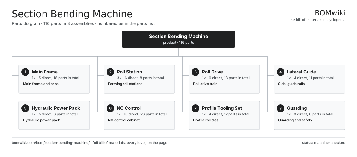
| # | Part | Qty | What it does |
|---|---|---|---|
| 1 | Main Frame 5 parts | 1× | Main frame and base |
| 2 | Roll Station 6 parts | 3× | Forming roll stations |
| 3 | Roll Drive 6 parts | 1× | Roll drive train |
| 4 | Lateral Guide 4 parts | 1× | Side-guide rolls |
| 5 | Hydraulic Power Pack 5 parts | 1× | Hydraulic power pack |
| 6 | NC Control 10 parts | 1× | NC control cabinet |
| 7 | Profile Tooling Set 4 parts | 1× | Profile roll dies |
| 8 | Guarding 3 parts | 1× | Guarding and safety |
3D model
No 3D model yet. Have a CAD file of this? Add a 3D model — STL renders right on this page; STEP, FreeCAD, and OpenSCAD sources are welcome too (openly licensed, like all 3D models on BOMwiki).
Build & assembly graph
expand / collapse · shared sub-assemblies converge · links to related products · est. labourTap an assembly to expand/collapse · tap a part to open it · use “Open page” for any node · drag to pan, scroll to zoom.
Bill of materials for Section Bending Machine
8 top-level lines · 51 rows shown · 116 parts total · indented to 3 levels| # | Item / sub-assembly | Part no. | Qty/assy | Ext. qty | Parts | Type |
|---|---|---|---|---|---|---|
| 1 | Main Frame 5 parts | section-bending-machine-frame | 1× | 1 | 18 | assembly |
| 1.1 | Frame Housing | section-bending-machine-housing | 1× | 1 | · | part |
| 1.2 | Bearing Block | section-bending-machine-bearing-block | 6× | 6 | · | part |
| 1.3 | Ball Bearing | ball-bearing | 6× | 6 | · | part |
| 1.4 | Leveling Pad | section-bending-machine-leveling-pad | 4× | 4 | · | part |
| 1.5 | Fastener Set | fastener-set | 1× | 1 | · | part |
| 2 | Roll Station 6 parts | section-bending-machine-roll-station | 3× | 3 | 8 | assembly |
| 2.1 | Roll Shaft | section-bending-machine-roll-shaft | 1× | 3 | · | part |
| 2.2 | Profile Roll Die | section-bending-machine-roll-die | 2× | 6 | · | part |
| 2.3 | Position Cylinder | section-bending-machine-position-cylinder | 1× | 3 | · | part |
| 2.4 | Position Encoder | section-bending-machine-position-encoder | 1× | 3 | · | part |
| 2.5 | Ball Bearing | ball-bearing | 2× | 6 | · | part |
| 2.6 | Oil Seal | oil-seal | 1× | 3 | · | part |
| 3 | Roll Drive 6 parts | section-bending-machine-drive | 1× | 1 | 13 | assembly |
| 3.1 | Drive Motor | section-bending-machine-drive-motor | 1× | 1 | · | part |
| 3.2 | Gearbox Housing | gearbox-housing | 1× | 1 | · | part |
| 3.3 | Helical Gear Pair | gear-pair | 3× | 3 | · | part |
| 3.4 | Roll Coupling | section-bending-machine-coupling | 2× | 2 | · | part |
| 3.5 | Ball Bearing | ball-bearing | 4× | 4 | · | part |
| 3.6 | Oil Seal | oil-seal | 2× | 2 | · | part |
| 4 | Lateral Guide 4 parts | section-bending-machine-lateral-guide | 1× | 1 | 11 | assembly |
| 4.1 | Guide Roll | section-bending-machine-guide-roll | 4× | 4 | · | part |
| 4.2 | Guide Arm | section-bending-machine-guide-arm | 2× | 2 | · | part |
| 4.3 | Ball Bearing | ball-bearing | 4× | 4 | · | part |
| 4.4 | Fastener Set | fastener-set | 1× | 1 | · | part |
| 5 | Hydraulic Power Pack 5 parts | section-bending-machine-hydraulic-unit | 1× | 1 | 6 | assembly |
| 5.1 | Hydraulic Pump | section-bending-machine-hydraulic-pump | 1× | 1 | · | part |
| 5.2 | Hydraulic Tank | section-bending-machine-hydraulic-tank | 1× | 1 | · | part |
| 5.3 | Valve Manifold | section-bending-machine-valve-block | 1× | 1 | · | part |
| 5.4 | Pressure Sensor | pressure-sensor | 2× | 2 | · | part |
| 5.5 | O-Ring Set | oring-set | 1× | 1 | · | part |
| 6 | NC Control 10 parts | section-bending-machine-control | 1× | 1 | 26 | assembly |
| 6.1 | Control Unit | section-bending-machine-control-unit | 1× | 1 | · | part |
| 6.2 | LCD Panel | lcd-panel | 1× | 1 | · | part |
| 6.3 | Power Supply | power-supply | 1× | 1 | · | part |
| 6.4 | Bare PCB | pcb-bare | 1× | 1 | · | part |
| 6.5 | Microcontroller | mcu | 1× | 1 | · | part |
| 6.6 | SMD Passive (R/C/L) | smd-passives | 1× | 1 | · | part |
| 6.7 | Relay | relay | 6× | 6 | · | part |
| 6.8 | Operator Pendant | section-bending-machine-pendant | 1× | 1 | · | part |
| 6.9 | Wire Bundle | wire-bundle | 1× | 1 | · | part |
| 6.10 | Connector | connector | 12× | 12 | · | part |
| 7 | Profile Tooling Set 4 parts | section-bending-machine-tooling-set | 1× | 1 | 12 | assembly |
| 7.1 | Angle Roll Die | section-bending-machine-angle-roll | 2× | 2 | · | part |
| 7.2 | Channel Roll Die | section-bending-machine-channel-roll | 2× | 2 | · | part |
| 7.3 | Tube Roll Die | section-bending-machine-tube-roll | 2× | 2 | · | part |
| 7.4 | Spacer Ring | section-bending-machine-spacer-ring | 6× | 6 | · | part |
| 8 | Guarding 3 parts | section-bending-machine-guard | 1× | 1 | 6 | assembly |
| 8.1 | Sheet Metal Panel | sheet-panel | 3× | 3 | · | part |
| 8.2 | Emergency Stop | section-bending-machine-estop | 2× | 2 | · | part |
| 8.3 | Trip Bar | section-bending-machine-trip-bar | 1× | 1 | · | part |
Related products
same domain, ranked by shared parts Angle Roll Bender
100 parts · shares 5 with this page
Centering and Facing Machine
1,419 parts · shares 5 with this page
CNC Metal Spinning Machine
768 parts · shares 5 with this page
Angle Roll Bender
100 parts · shares 5 with this page
Centering and Facing Machine
1,419 parts · shares 5 with this page
CNC Metal Spinning Machine
768 parts · shares 5 with this page
 Continuous Belt Furnace
130 parts · shares 5 with this page
Continuous Belt Furnace
130 parts · shares 5 with this page
 Creep-Feed Grinder
571 parts · shares 5 with this page
Cut-to-Length Line
500 parts · shares 5 with this page
Creep-Feed Grinder
571 parts · shares 5 with this page
Cut-to-Length Line
500 parts · shares 5 with this page
Sourcing: possible vendors
Prices, MOQ, and lead times are algorithmic estimates, not quotes, and not claims about these companies. Company mappings are curated by keyword; est. price band $10k–$1M. How estimates work| Vendor | HQ | Specialty | MOQ | Lead time |
|---|---|---|---|---|
|
🇩🇪DMG MORI
dmgmori.com ↗
|
Bielefeld, DE | Machine tools | 5 units | 12–20 wks |
|
🇯🇵Mazak
mazak.com ↗
|
Oguchi, JP | Machine tools | 5 units | 12–20 wks |
| haascnc.com ↗ | Oxnard, US | CNC machine tools | 5 units | 12–20 wks |
|
🇯🇵Okuma
okuma.com ↗
|
Niwa, JP | Machine tools | 5 units | 12–20 wks |
|
🇩🇪Trumpf
trumpf.com ↗
|
Ditzingen, DE | Laser & sheet-metal machines | 5 units | 12–20 wks |
952-word article