Hot Rolling Mill
ProductHot Rolling Mill
A Hot Rolling Mill reduces a thick, reheated steel slab into plate, strip or sectional product by passing it between two rotating rolls. The slab leaves a reheat furnace at 1100-1250 C, hot enough that the steel deforms plastically at low flow stress. As the metal enters the gap between the work rolls it is squeezed thinner and pushed longer, while its width changes little. A single Hot Rolling Mill stand of the four-high reversing type can take a slab back and forth through the same gap many times, closing the rolls a little on each pass until the target thickness is reached. Finishing mills instead run several stands in a continuous line, each taking one bite.
The headline numbers come from the geometry and the load. A 210 mm slab can finish at 2-25 mm, the separating force between the rolls reaches about 25 MN, and the main motor delivers roughly 8 MW to overcome roll torque at speeds up to 7 m/s.
Mill stand and housing
The structural load path is the Mill Stand. Two cast steel Housing Post uprights stand on a Sole Plate bolted into the foundation, and a Housing Cap closes the top of each window. Four Tie Rod bars are pre-tensioned to clamp the cap and posts into a stiff closed frame, so that the rolling force stretches the housing elastically rather than opening a joint. The inside faces of the window run on replaceable Window Liner Plate wear plates, and a Window Guide on each side locates the roll chocks as they move up and down. Housing stiffness matters directly: any springback of the stand under load shows up as thickness error in the strip, so the frame is sized for very small deflection at full force.
Roll set and chocks
The working part is the Roll Set, a four-high stack. Two forged Work Roll barrels of about 700 mm diameter touch the strip and do the deforming. Because slim work rolls would bend under 25 MN, each is backed by a much larger Back-up Roll of about 1500 mm diameter that carries most of the separating force and keeps the work roll straight. Every roll neck sits in a Work Roll Chock or Back-up Roll Chock, a cast housing that slides in the window. The work rolls run on rolling-element bearings using a shared Ball Bearing, while the back-up roll necks ride on a hydrodynamic Oil-Film Bearing, a Morgoil-style sleeve whose Bearing Bushing and Bearing Sleeve float the neck on a pressurised oil film. Each neck is closed by an Oil Seal to keep mill scale and cooling water out of the bearing.
Screwdown and hydraulic gap control
Roll gap is set in two stages. Coarse positioning comes from the Screwdown Mechanism: two large Screwdown Screw power screws turn in bronze Screwdown Nut seats in the housing cap, driven through the Screwdown Gearbox by a Screwdown Motor so both columns move together. A Load Cell under each column reads rolling force, and a Position Encoder reports screw position. Fine, fast correction comes from the Hydraulic Gap Control, a hydraulic capsule under the bottom chock. Each HGC Capsule Cylinder is fed by a high-response Servo Valve and trimmed by a Capsule Position Sensor reading capsule stroke to about one micron. The gauge controller compares load-cell force and exit thickness against the target and adjusts the capsule on every revolution, holding tolerance the screwdown alone could not reach.
Main drive train
Torque reaches the rolls through the Main Drive. The roughly 8 MW Main Drive Motor feeds a Pinion Stand, a gear distributor that splits torque to two output shafts so the top and bottom work rolls turn at the same speed. From there a Universal Spindle on each side carries torque into the work roll. Each spindle uses a Spindle Universal Joint at both ends so it keeps driving as the roll gap, and therefore the roll height, changes during rolling. A Gear Coupling links the motor, pinion stand and spindles, and a Flywheel adds inertia that smooths the torque spike when the slab first bites.
Roller tables, descaling and cooling
Slabs reach and leave the stand on the Roller Tables. Driven Roller-Table Roll rolls, each turned by a Roller-Table Motor, convey the bar, while a Side Guide centres it and, on a plate mill, a Plate Manipulator turns and squares the piece between passes. Before the first reduction a Descaling Header fitted with many Descaling Nozzle jets, fed by a Descaling Pump at about 200 bar, blasts the oxide scale off the hot surface so it is not rolled into the steel. Roll life depends on the Cooling & Lubrication system, where a Roll Cooling Header and its Cooling Spray Nozzle array flood the work rolls with water, and a Lubrication Pump with an Oil Cooler circulates oil to the bearings and spindles.
Hydraulics, shape control and controls
Hydraulic power for HGC, bending and guides comes from the Hydraulic Power Unit, where a Hydraulic Pump charges several Accumulator units and feeds a Valve Manifold monitored by a Pressure Sensor. Strip flatness is set by the Roll Bending System system, whose Bending Cylinder and Balance Cylinder act through the Bending Block to vary roll crown. The whole line is coordinated by the Control System: a Mill Control Board runs gauge and shape regulation, a Drive Control Cabinet cabinet commands the motors, and a Pyrometer feeds strip temperature back so the model can correct for how flow stress changes as the steel cools. Variants range from heavy plate mills running a single reversing stand to hot strip finishing trains of six or seven stands in series, but the building blocks stay the same.
Hot Rolling Mill parts and their functions
10 top-level parts · 1,363 parts in total · full bill of materials below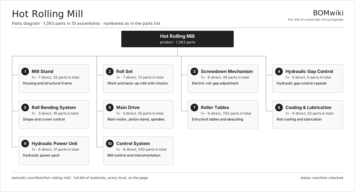
| # | Part | Qty | What it does |
|---|---|---|---|
| 1 | Mill Stand 7 parts | 1× | Housing and structural frame |
| 2 | Roll Set 7 parts | 1× | Work and back-up rolls with chocks |
| 3 | Screwdown Mechanism 6 parts | 1× | Electric roll-gap adjustment |
| 4 | Hydraulic Gap Control 5 parts | 1× | Hydraulic gap control capsule |
| 5 | Roll Bending System 5 parts | 1× | Shape and crown control |
| 6 | Main Drive 5 parts | 1× | Main motor, pinion stand, spindles |
| 7 | Roller Tables 6 parts | 1× | Entry/exit tables and descaling |
| 8 | Cooling & Lubrication 6 parts | 1× | Roll cooling and lubrication |
| 9 | Hydraulic Power Unit 6 parts | 1× | Hydraulic power pack |
| 10 | Control System 8 parts | 1× | Mill control and instrumentation |
3D model
No 3D model yet. Have a CAD file of this? Add a 3D model — STL renders right on this page; STEP, FreeCAD, and OpenSCAD sources are welcome too (openly licensed, like all 3D models on BOMwiki).
Build & assembly graph
expand / collapse · shared sub-assemblies converge · links to related products · est. labourTap an assembly to expand/collapse · tap a part to open it · use “Open page” for any node · drag to pan, scroll to zoom.
Bill of materials for Hot Rolling Mill
10 top-level lines · 137 rows shown · 1,363 parts total · indented to 3 levels| # | Item / sub-assembly | Part no. | Qty/assy | Ext. qty | Parts | Type |
|---|---|---|---|---|---|---|
| 1 | Mill Stand 7 parts | hot-rolling-mill-stand | 1× | 1 | 23 | assembly |
| 1.1 | Housing Post | hot-rolling-mill-housing-post | 2× | 2 | · | part |
| 1.2 | Housing Cap | hot-rolling-mill-housing-cap | 2× | 2 | · | part |
| 1.3 | Tie Rod | hot-rolling-mill-tie-rod | 4× | 4 | · | part |
| 1.4 | Sole Plate | hot-rolling-mill-sole-plate | 2× | 2 | · | part |
| 1.5 | Window Liner Plate | hot-rolling-mill-liner-plate | 8× | 8 | · | part |
| 1.6 | Window Guide | hot-rolling-mill-window-guide | 4× | 4 | · | part |
| 1.7 | Fastener Set | fastener-set | 1× | 1 | · | part |
| 2 | Roll Set 7 parts | hot-rolling-mill-roll-set | 1× | 1 | 72 | assembly |
| 2.1 | Work Roll | hot-rolling-mill-work-roll | 2× | 2 | · | part |
| 2.2 | Back-up Roll | hot-rolling-mill-backup-roll | 2× | 2 | · | part |
| 2.3 | Work Roll Chock 4 parts | hot-rolling-mill-work-chock | 4× | 4 | 4 | assembly |
| 2.3.1 | Chock Body | hot-rolling-mill-chock-body | 1× | 4 | · | part |
| 2.3.2 | Ball Bearing | ball-bearing | 1× | 4 | · | part |
| 2.3.3 | Oil Seal | oil-seal | 1× | 4 | · | part |
| 2.3.4 | Roll Balance Pad | hot-rolling-mill-balance-pad | 1× | 4 | · | part |
| 2.4 | Back-up Roll Chock 3 parts | hot-rolling-mill-backup-chock | 4× | 4 | 6 | assembly |
| 2.4.1 | Chock Body | hot-rolling-mill-chock-body | 1× | 4 | · | part |
| 2.4.2 | Oil-Film Bearing 3 parts + deeper › | hot-rolling-mill-oilfilm-bearing | 1× | 4 | 4 | assembly |
| 2.4.3 | Oil Seal | oil-seal | 1× | 4 | · | part |
| 2.5 | Oil-Film Bearing 3 parts | hot-rolling-mill-oilfilm-bearing | 4× | 4 | 4 | assembly |
| 2.5.1 | Bearing Bushing | hot-rolling-mill-bearing-bushing | 1× | 4 | · | part |
| 2.5.2 | Bearing Sleeve | hot-rolling-mill-bearing-sleeve | 1× | 4 | · | part |
| 2.5.3 | Oil Seal | oil-seal | 2× | 8 | · | part |
| 2.6 | Ball Bearing | ball-bearing | 4× | 4 | · | part |
| 2.7 | Oil Seal | oil-seal | 8× | 8 | · | part |
| 3 | Screwdown Mechanism 6 parts | hot-rolling-mill-screwdown | 1× | 1 | 48 | assembly |
| 3.1 | Screwdown Screw | hot-rolling-mill-screwdown-screw | 2× | 2 | · | part |
| 3.2 | Screwdown Nut | hot-rolling-mill-screwdown-nut | 2× | 2 | · | part |
| 3.3 | Screwdown Gearbox 4 parts | hot-rolling-mill-screwdown-gearbox | 1× | 1 | 13 | assembly |
| 3.3.1 | Gearbox Housing | gearbox-housing | 1× | 1 | · | part |
| 3.3.2 | Helical Gear Pair | gear-pair | 2× | 2 | · | part |
| 3.3.3 | Ball Bearing | ball-bearing | 6× | 6 | · | part |
| 3.3.4 | Oil Seal | oil-seal | 4× | 4 | · | part |
| 3.4 | Screwdown Motor 6 parts | hot-rolling-mill-screwdown-motor | 1× | 1 | 27 | assembly |
| 3.4.1 | Stator Assembly 3 parts + deeper › | stator-assembly | 1× | 1 | 3 | assembly |
| 3.4.2 | Rotor Assembly 4 parts + deeper › | rotor-assembly | 1× | 1 | 19 | assembly |
| 3.4.3 | Copper Winding | copper-winding | 1× | 1 | · | part |
| 3.4.4 | Motor Housing | motor-housing | 1× | 1 | · | part |
| 3.4.5 | Ball Bearing | ball-bearing | 2× | 2 | · | part |
| 3.4.6 | Position Encoder | hot-rolling-mill-position-encoder | 1× | 1 | · | part |
| 3.5 | Load Cell | hot-rolling-mill-load-cell | 2× | 2 | · | part |
| 3.6 | Position Encoder | hot-rolling-mill-position-encoder | 2× | 2 | · | part |
| 4 | Hydraulic Gap Control 5 parts | hot-rolling-mill-hgc | 1× | 1 | 9 | assembly |
| 4.1 | HGC Capsule Cylinder | hot-rolling-mill-hgc-cylinder | 2× | 2 | · | part |
| 4.2 | Servo Valve | hot-rolling-mill-servo-valve | 2× | 2 | · | part |
| 4.3 | Capsule Position Sensor | hot-rolling-mill-position-sensor | 2× | 2 | · | part |
| 4.4 | Load Cell | hot-rolling-mill-load-cell | 2× | 2 | · | part |
| 4.5 | O-Ring Set | oring-set | 1× | 1 | · | part |
| 5 | Roll Bending System 5 parts | hot-rolling-mill-roll-bending | 1× | 1 | 19 | assembly |
| 5.1 | Bending Block | hot-rolling-mill-bending-block | 4× | 4 | · | part |
| 5.2 | Bending Cylinder | hot-rolling-mill-bending-cylinder | 8× | 8 | · | part |
| 5.3 | Balance Cylinder | hot-rolling-mill-balance-cylinder | 4× | 4 | · | part |
| 5.4 | Servo Valve | hot-rolling-mill-servo-valve | 2× | 2 | · | part |
| 5.5 | O-Ring Set | oring-set | 1× | 1 | · | part |
| 6 | Main Drive 5 parts | hot-rolling-mill-main-drive | 1× | 1 | 55 | assembly |
| 6.1 | Main Drive Motor 6 parts | hot-rolling-mill-main-motor | 1× | 1 | 27 | assembly |
| 6.1.1 | Stator Assembly 3 parts + deeper › | stator-assembly | 1× | 1 | 3 | assembly |
| 6.1.2 | Rotor Assembly 4 parts + deeper › | rotor-assembly | 1× | 1 | 19 | assembly |
| 6.1.3 | Copper Winding | copper-winding | 1× | 1 | · | part |
| 6.1.4 | Motor Housing | motor-housing | 1× | 1 | · | part |
| 6.1.5 | Ball Bearing | ball-bearing | 2× | 2 | · | part |
| 6.1.6 | Position Encoder | hot-rolling-mill-position-encoder | 1× | 1 | · | part |
| 6.2 | Pinion Stand 4 parts | hot-rolling-mill-pinion-stand | 1× | 1 | 15 | assembly |
| 6.2.1 | Gearbox Housing | gearbox-housing | 1× | 1 | · | part |
| 6.2.2 | Helical Gear Pair | gear-pair | 2× | 2 | · | part |
| 6.2.3 | Ball Bearing | ball-bearing | 8× | 8 | · | part |
| 6.2.4 | Oil Seal | oil-seal | 4× | 4 | · | part |
| 6.3 | Universal Spindle 3 parts | hot-rolling-mill-spindle | 2× | 2 | 5 | assembly |
| 6.3.1 | Spindle Shaft | hot-rolling-mill-spindle-shaft | 1× | 2 | · | part |
| 6.3.2 | Spindle Universal Joint | hot-rolling-mill-spindle-joint | 2× | 4 | · | part |
| 6.3.3 | Oil Seal | oil-seal | 2× | 4 | · | part |
| 6.4 | Gear Coupling | hot-rolling-mill-coupling | 2× | 2 | · | part |
| 6.5 | Flywheel | hot-rolling-mill-flywheel | 1× | 1 | · | part |
| 7 | Roller Tables 6 parts | hot-rolling-mill-roller-tables | 1× | 1 | 703 | assembly |
| 7.1 | Roller-Table Roll | hot-rolling-mill-table-roller | 24× | 24 | · | part |
| 7.2 | Roller-Table Motor 5 parts | hot-rolling-mill-table-roller-motor | 24× | 24 | 26 | assembly |
| 7.2.1 | Stator Assembly 3 parts + deeper › | stator-assembly | 1× | 24 | 3 | assembly |
| 7.2.2 | Rotor Assembly 4 parts + deeper › | rotor-assembly | 1× | 24 | 19 | assembly |
| 7.2.3 | Copper Winding | copper-winding | 1× | 24 | · | part |
| 7.2.4 | Motor Housing | motor-housing | 1× | 24 | · | part |
| 7.2.5 | Ball Bearing | ball-bearing | 2× | 48 | · | part |
| 7.3 | Side Guide | hot-rolling-mill-side-guide | 2× | 2 | · | part |
| 7.4 | Plate Manipulator | hot-rolling-mill-manipulator | 2× | 2 | · | part |
| 7.5 | Descaling Header 3 parts | hot-rolling-mill-descale-header | 2× | 2 | 22 | assembly |
| 7.5.1 | Descaling Nozzle | hot-rolling-mill-descale-nozzle | 20× | 40 | · | part |
| 7.5.2 | O-Ring Set | oring-set | 1× | 2 | · | part |
| 7.5.3 | Fastener Set | fastener-set | 1× | 2 | · | part |
| 7.6 | Descaling Pump 4 parts | hot-rolling-mill-descale-pump | 1× | 1 | 7 | assembly |
| 7.6.1 | Pump Block | hot-rolling-mill-pump-block | 1× | 1 | · | part |
| 7.6.2 | Pump Plunger | hot-rolling-mill-plunger | 3× | 3 | · | part |
| 7.6.3 | O-Ring Set | oring-set | 1× | 1 | · | part |
| 7.6.4 | Ball Bearing | ball-bearing | 2× | 2 | · | part |
| 8 | Cooling & Lubrication 6 parts | hot-rolling-mill-cooling-lube | 1× | 1 | 53 | assembly |
| 8.1 | Roll Cooling Header | hot-rolling-mill-cooling-header | 4× | 4 | · | part |
| 8.2 | Cooling Spray Nozzle | hot-rolling-mill-spray-nozzle | 40× | 40 | · | part |
| 8.3 | Lubrication Pump 4 parts | hot-rolling-mill-lube-pump | 1× | 1 | 6 | assembly |
| 8.3.1 | Pump Block | hot-rolling-mill-pump-block | 1× | 1 | · | part |
| 8.3.2 | Ball Bearing | ball-bearing | 2× | 2 | · | part |
| 8.3.3 | Oil Seal | oil-seal | 2× | 2 | · | part |
| 8.3.4 | O-Ring Set | oring-set | 1× | 1 | · | part |
| 8.4 | Oil Cooler | hot-rolling-mill-oil-cooler | 1× | 1 | · | part |
| 8.5 | Lube Oil Tank | hot-rolling-mill-oil-tank | 1× | 1 | · | part |
| 8.6 | Oil Distribution Lines | hot-rolling-mill-oil-line | 1× | 1 | · | part |
| 9 | Hydraulic Power Unit 6 parts | hot-rolling-mill-hydraulic-unit | 1× | 1 | 31 | assembly |
| 9.1 | Hydraulic Pump 4 parts | hot-rolling-mill-hydraulic-pump | 2× | 2 | 6 | assembly |
| 9.1.1 | Pump Block | hot-rolling-mill-pump-block | 1× | 2 | · | part |
| 9.1.2 | Ball Bearing | ball-bearing | 2× | 4 | · | part |
| 9.1.3 | Oil Seal | oil-seal | 2× | 4 | · | part |
| 9.1.4 | O-Ring Set | oring-set | 1× | 2 | · | part |
| 9.2 | Accumulator | hot-rolling-mill-accumulator | 4× | 4 | · | part |
| 9.3 | Valve Manifold 3 parts | hot-rolling-mill-valve-manifold | 1× | 1 | 6 | assembly |
| 9.3.1 | Manifold Block | hot-rolling-mill-manifold-block | 1× | 1 | · | part |
| 9.3.2 | Servo Valve | hot-rolling-mill-servo-valve | 4× | 4 | · | part |
| 9.3.3 | O-Ring Set | oring-set | 1× | 1 | · | part |
| 9.4 | Hydraulic Reservoir | hot-rolling-mill-reservoir | 1× | 1 | · | part |
| 9.5 | Hydraulic Filter | hot-rolling-mill-filter | 4× | 4 | · | part |
| 9.6 | Pressure Sensor | pressure-sensor | 4× | 4 | · | part |
| 10 | Control System 8 parts | hot-rolling-mill-control-system | 1× | 1 | 350 | assembly |
| 10.1 | Mill Control Board 5 parts | hot-rolling-mill-control-board | 1× | 1 | 216 | assembly |
| 10.1.1 | Bare PCB | pcb-bare | 1× | 1 | · | part |
| 10.1.2 | Microcontroller | mcu | 2× | 2 | · | part |
| 10.1.3 | Connector | connector | 12× | 12 | · | part |
| 10.1.4 | SMD Passive (R/C/L) | smd-passives | 200× | 200 | · | part |
| 10.1.5 | Power Supply | power-supply | 1× | 1 | · | part |
| 10.2 | Drive Control Cabinet 5 parts | hot-rolling-mill-drive-control | 1× | 1 | 41 | assembly |
| 10.2.1 | Bare PCB | pcb-bare | 2× | 2 | · | part |
| 10.2.2 | Microcontroller | mcu | 1× | 1 | · | part |
| 10.2.3 | Relay | relay | 12× | 12 | · | part |
| 10.2.4 | Connector | connector | 24× | 24 | · | part |
| 10.2.5 | Power Supply | power-supply | 2× | 2 | · | part |
| 10.3 | Pyrometer | hot-rolling-mill-pyrometer | 2× | 2 | · | part |
| 10.4 | Pressure Sensor | pressure-sensor | 4× | 4 | · | part |
| 10.5 | Load Cell | hot-rolling-mill-load-cell | 2× | 2 | · | part |
| 10.6 | Wire Bundle | wire-bundle | 1× | 1 | · | part |
| 10.7 | Relay | relay | 24× | 24 | · | part |
| 10.8 | Connector | connector | 60× | 60 | · | part |
Related products
same domain, ranked by shared parts Angle Roll Bender
100 parts · shares 3 with this page
Angle Roll Bender
100 parts · shares 3 with this page
 Bed-Type Milling Machine
151 parts · shares 3 with this page
Bed-Type Milling Machine
151 parts · shares 3 with this page
 Bevel Gear Generator
201 parts · shares 3 with this page
Bevel Gear Generator
201 parts · shares 3 with this page
 Capstan Lathe
197 parts · shares 3 with this page
Centering and Facing Machine
1,419 parts · shares 3 with this page
CNC Metal Spinning Machine
768 parts · shares 3 with this page
Capstan Lathe
197 parts · shares 3 with this page
Centering and Facing Machine
1,419 parts · shares 3 with this page
CNC Metal Spinning Machine
768 parts · shares 3 with this page
Sourcing: possible vendors
Prices, MOQ, and lead times are algorithmic estimates, not quotes, and not claims about these companies. Company mappings are curated by keyword; est. price band $10k–$1M. How estimates work| Vendor | HQ | Specialty | MOQ | Lead time |
|---|---|---|---|---|
|
🇩🇪DMG MORI
dmgmori.com ↗
|
Bielefeld, DE | Machine tools | 5 units | 12–20 wks |
|
🇯🇵Mazak
mazak.com ↗
|
Oguchi, JP | Machine tools | 5 units | 12–20 wks |
| haascnc.com ↗ | Oxnard, US | CNC machine tools | 5 units | 12–20 wks |
|
🇯🇵Okuma
okuma.com ↗
|
Niwa, JP | Machine tools | 5 units | 12–20 wks |
|
🇩🇪Trumpf
trumpf.com ↗
|
Ditzingen, DE | Laser & sheet-metal machines | 5 units | 12–20 wks |
1,117-word article