Strip Edge Trimming Machine
ProductOverview
A strip edge trimming machine takes rolled metal strip whose edges are uneven, wavy, or burred from the rolling mill and shears both sides to an exact width with a clean, square edge. It is a continuous coil-to-coil line: a full coil is loaded on the Uncoiler, threaded through a Trimming Head that carries two rotary slitter cartridges, and rewound on the Recoiler. The narrow ribbons cut off each edge are chopped and removed by the Scrap Handling system. Edge trimming is a routine step ahead of slitting, tube welding, stamping, and any process where edge straightness and a known width matter.
Payoff and coil handling
The incoming coil sits on the Uncoiler, a powered reel built around an Expanding Mandrel. This mandrel uses four Mandrel Segment jaws driven outward by an internal Expansion Cylinder, so one mandrel grips any coil within its inner-diameter range, typically 508 mm and 610 mm. A Coil Loading Car with a hydraulic V-saddle lifts the coil from the floor and centers it on the mandrel before expansion. The Uncoiler Drive is a servo geared through the Reduction Gearbox and runs in torque mode to hold back-tension on the strip, while a Coil Hold-Down Arm arm presses on the coil OD to stop clock-spring loosening when the line stops.
Trimming head
The cutting work happens at the Trimming Head. Two Slitter Cartridge units, one per edge, each hold an upper and lower Circular Trim Knife mounted on a ground Knife Arbor. The knives overlap slightly and run with a small horizontal clearance; as the strip passes between them they shear it the way scissors do, leaving a square edge rather than the torn edge a single blade would produce. Knife clearance is set with stacked Precision Spacer rings, and a Stripper Ring lifts the trimmed strip off the knife so it does not wrap.
Trim width is set by the Width Adjustment, a motorized stage running two Ball Screw actuators on Linear Guide Rail rails, positioning each cartridge against a Linear Position Encoder for ±0.05 mm repeatability. The Head Drive turns the arbors through a Helical Gear Pair and Cardan Drive Shaft couplings so peripheral knife speed matches strip speed and the edge is sheared, not dragged.
Scrap handling
The two ribbons cut from the edges cannot be allowed to pile up. Each one feeds into an Edge Scrap Chopper, a crash-roll unit whose Chopper Blade sets cut the sliver into 50 to 100 mm pieces. The pieces drop onto the Scrap Conveyor, a steel-belt conveyor that carries them to an Scrap Baller or a bin. Chopping keeps the scrap dense and feedable to a remelt furnace; an alternative on some lines coils the trim ribbon onto a separate scrap winder.
Tension and guiding
Edge quality depends on holding the strip flat and on the centerline as it crosses the knives. The Tension Bridle is a four-roll S-wrap whose driven Bridle Roll sets isolate tension in the cutting zone, monitored by a Tension Load Cell. The Strip Guide System uses an Edge Position Sensor pair to read the strip position and a Guide Actuator to steer the entry rolls, keeping the strip centered to the knives so both trims are equal.
Power, control, and frame
The Hydraulic Power Unit supplies the mandrel cylinders, coil car, and hold-down at 160 bar, with a Accumulator for peak demand and a Pressure Sensor pair for monitoring. The Control System runs the line from a PLC Controller; the Drive Cabinet holds the Variable Frequency Drive drives and a Power Supply, and the operator works from a HMI Touch Panel panel built on an LCD Panel. All of it bolts to the welded Machine Frame, leveled on Leveling Foot mounts and clad in Sheet Metal Panel guarding.
Use and variants
Edge trimming lines feed tube and pipe mills, which need a precise width to form a good weld seam, and they prepare strip for stamping where a burred edge would crack on the first draw. Smaller lines trim narrow strip for connectors and lead frames; heavy lines handle 4 mm structural strip at 25 t coils. The choice of Circular Trim Knife grade and the knife clearance setting are matched to material and thickness to keep burr height under roughly 8% of strip thickness.
Knife clearance is the single most important setting on the machine. Too much clearance leaves a large burr and a torn secondary shear zone; too little wears the knives quickly and can cause them to rub. The setting is a percentage of strip thickness, typically 5 to 10 percent, dialed in with the Precision Spacer stack. Soft aluminum runs tighter clearance than hard stainless. Knife life between regrinds depends on material and runs from a few coils on abrasive grades to many tonnes on mild steel. Operators check edge quality with the first coil and adjust the Knife Overlap Adjuster and clearance before committing the run, since a bad edge propagates through every downstream process.
Strip Edge Trimming Machine parts and their functions
9 top-level parts · 491 parts in total · full bill of materials below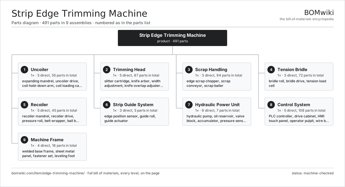
| # | Part | Qty | What it does |
|---|---|---|---|
| 1 | Uncoiler 5 parts | 1× | Mandrel-type payoff reel that holds the incoming coil and feeds strip into the line. |
| 2 | Trimming Head 5 parts | 1× | Pair of rotary slitter cartridges that shear both strip edges to a set width. |
| 3 | Scrap Handling 3 parts | 1× | Choppers and conveyor that cut the trimmed edge strips into short scrap and remove them. |
| 4 | Tension Bridle 3 parts | 1× | Multi-roll S-wrap that isolates and controls strip tension across the trimming zone. |
| 5 | Recoiler 5 parts | 1× | Driven mandrel that winds the trimmed strip into a tight, edge-aligned coil. |
| 6 | Strip Guide System 3 parts | 1× | Center-position guide that keeps the strip aligned to the knife centerline. |
| 7 | Hydraulic Power Unit 6 parts | 1× | Pump, reservoir, and valve bank supplying mandrel expansion and cylinder functions. |
| 8 | Control System 5 parts | 1× | PLC and drive cabinet coordinating tension, knife position, and line speed. |
| 9 | Machine Frame 4 parts | 1× | Welded steel base and stands carrying the line modules on a common centerline. |
3D model
No 3D model yet. Have a CAD file of this? Add a 3D model — STL renders right on this page; STEP, FreeCAD, and OpenSCAD sources are welcome too (openly licensed, like all 3D models on BOMwiki).
Build & assembly graph
expand / collapse · shared sub-assemblies converge · links to related products · est. labourTap an assembly to expand/collapse · tap a part to open it · use “Open page” for any node · drag to pan, scroll to zoom.
Bill of materials for Strip Edge Trimming Machine
9 top-level lines · 93 rows shown · 491 parts total · indented to 3 levels| # | Item / sub-assembly | Part no. | Qty/assy | Ext. qty | Parts | Type |
|---|---|---|---|---|---|---|
| 1 | Uncoiler 5 parts | edge-trimming-machine-uncoiler | 1× | 1 | 55 | assembly |
| 1.1 | Expanding Mandrel 4 parts | edge-trimming-machine-uncoiler-mandrel | 1× | 1 | 10 | assembly |
| 1.1.1 | Mandrel Segment | edge-trimming-machine-mandrel-segment | 4× | 4 | · | part |
| 1.1.2 | Mandrel Wedge | edge-trimming-machine-mandrel-wedge | 4× | 4 | · | part |
| 1.1.3 | Expansion Cylinder | edge-trimming-machine-mandrel-cylinder | 1× | 1 | · | part |
| 1.1.4 | Mandrel Shaft | edge-trimming-machine-mandrel-shaft | 1× | 1 | · | part |
| 1.2 | Uncoiler Drive 3 parts | edge-trimming-machine-uncoiler-drive | 1× | 1 | 34 | assembly |
| 1.2.1 | Servo Motor 4 parts + deeper › | servo-motor | 1× | 1 | 24 | assembly |
| 1.2.2 | Reduction Gearbox 4 parts + deeper › | edge-trimming-machine-gearbox | 1× | 1 | 9 | assembly |
| 1.2.3 | Tension Brake Disc | edge-trimming-machine-brake-disc | 1× | 1 | · | part |
| 1.3 | Coil Hold-Down Arm | edge-trimming-machine-uncoiler-hold-down | 1× | 1 | · | part |
| 1.4 | Coil Loading Car 3 parts | edge-trimming-machine-uncoiler-coil-car | 1× | 1 | 6 | assembly |
| 1.4.1 | V-Saddle | edge-trimming-machine-coil-car-saddle | 1× | 1 | · | part |
| 1.4.2 | Lift Cylinder | edge-trimming-machine-coil-car-cylinder | 1× | 1 | · | part |
| 1.4.3 | Car Wheel | edge-trimming-machine-coil-car-wheel | 4× | 4 | · | part |
| 1.5 | Ball Bearing | ball-bearing | 4× | 4 | · | part |
| 2 | Trimming Head 5 parts | edge-trimming-machine-trimming-head | 1× | 1 | 87 | assembly |
| 2.1 | Slitter Cartridge 4 parts | edge-trimming-machine-slitter-cartridge | 2× | 2 | 14 | assembly |
| 2.1.1 | Circular Trim Knife | edge-trimming-machine-circular-knife | 2× | 4 | · | part |
| 2.1.2 | Precision Spacer | edge-trimming-machine-knife-spacer | 6× | 12 | · | part |
| 2.1.3 | Stripper Ring | edge-trimming-machine-stripper-ring | 2× | 4 | · | part |
| 2.1.4 | Ball Bearing | ball-bearing | 4× | 8 | · | part |
| 2.2 | Knife Arbor | edge-trimming-machine-arbor | 2× | 2 | · | part |
| 2.3 | Width Adjustment 4 parts | edge-trimming-machine-width-adjust | 1× | 1 | 29 | assembly |
| 2.3.1 | Ball Screw | ball-screw | 2× | 2 | · | part |
| 2.3.2 | Servo Motor 4 parts + deeper › | servo-motor | 1× | 1 | 24 | assembly |
| 2.3.3 | Linear Guide Rail | linear-guide | 2× | 2 | · | part |
| 2.3.4 | Linear Position Encoder | edge-trimming-machine-position-encoder | 1× | 1 | · | part |
| 2.4 | Knife Overlap Adjuster | edge-trimming-machine-overlap-adjust | 1× | 1 | · | part |
| 2.5 | Head Drive 3 parts | edge-trimming-machine-head-drive | 1× | 1 | 27 | assembly |
| 2.5.1 | Servo Motor 4 parts + deeper › | servo-motor | 1× | 1 | 24 | assembly |
| 2.5.2 | Helical Gear Pair | gear-pair | 1× | 1 | · | part |
| 2.5.3 | Cardan Drive Shaft | edge-trimming-machine-cardan-shaft | 2× | 2 | · | part |
| 3 | Scrap Handling 3 parts | edge-trimming-machine-scrap-handling | 1× | 1 | 94 | assembly |
| 3.1 | Edge Scrap Chopper 3 parts | edge-trimming-machine-scrap-chopper | 2× | 2 | 30 | assembly |
| 3.1.1 | Chopper Roll | edge-trimming-machine-chopper-roll | 2× | 4 | · | part |
| 3.1.2 | Chopper Blade | edge-trimming-machine-chopper-blade | 4× | 8 | · | part |
| 3.1.3 | Servo Motor 4 parts + deeper › | servo-motor | 1× | 2 | 24 | assembly |
| 3.2 | Scrap Conveyor 3 parts | edge-trimming-machine-scrap-conveyor | 1× | 1 | 33 | assembly |
| 3.2.1 | Drive Belt | drive-belt | 1× | 1 | · | part |
| 3.2.2 | Conveyor Roller | edge-trimming-machine-conveyor-roller | 8× | 8 | · | part |
| 3.2.3 | Servo Motor 4 parts + deeper › | servo-motor | 1× | 1 | 24 | assembly |
| 3.3 | Scrap Baller | edge-trimming-machine-scrap-baller | 1× | 1 | · | part |
| 4 | Tension Bridle 3 parts | edge-trimming-machine-tension-bridle | 1× | 1 | 72 | assembly |
| 4.1 | Bridle Roll | edge-trimming-machine-bridle-roll | 4× | 4 | · | part |
| 4.2 | Bridle Drive 2 parts | edge-trimming-machine-bridle-drive | 2× | 2 | 33 | assembly |
| 4.2.1 | Servo Motor 4 parts + deeper › | servo-motor | 1× | 2 | 24 | assembly |
| 4.2.2 | Reduction Gearbox 4 parts + deeper › | edge-trimming-machine-gearbox | 1× | 2 | 9 | assembly |
| 4.3 | Tension Load Cell | edge-trimming-machine-load-cell | 2× | 2 | · | part |
| 5 | Recoiler 5 parts | edge-trimming-machine-recoiler | 1× | 1 | 45 | assembly |
| 5.1 | Recoiler Mandrel 3 parts | edge-trimming-machine-recoiler-mandrel | 1× | 1 | 6 | assembly |
| 5.1.1 | Mandrel Segment | edge-trimming-machine-mandrel-segment | 4× | 4 | · | part |
| 5.1.2 | Expansion Cylinder | edge-trimming-machine-mandrel-cylinder | 1× | 1 | · | part |
| 5.1.3 | Mandrel Shaft | edge-trimming-machine-mandrel-shaft | 1× | 1 | · | part |
| 5.2 | Recoiler Drive 2 parts | edge-trimming-machine-recoiler-drive | 1× | 1 | 33 | assembly |
| 5.2.1 | Servo Motor 4 parts + deeper › | servo-motor | 1× | 1 | 24 | assembly |
| 5.2.2 | Reduction Gearbox 4 parts + deeper › | edge-trimming-machine-gearbox | 1× | 1 | 9 | assembly |
| 5.3 | Pressure Roll | edge-trimming-machine-pressure-roll | 1× | 1 | · | part |
| 5.4 | Belt Wrapper | edge-trimming-machine-belt-wrapper | 1× | 1 | · | part |
| 5.5 | Ball Bearing | ball-bearing | 4× | 4 | · | part |
| 6 | Strip Guide System 3 parts | edge-trimming-machine-strip-guide | 1× | 1 | 5 | assembly |
| 6.1 | Edge Position Sensor | edge-trimming-machine-edge-sensor | 2× | 2 | · | part |
| 6.2 | Guide Roll | edge-trimming-machine-guide-roll | 2× | 2 | · | part |
| 6.3 | Guide Actuator | edge-trimming-machine-guide-actuator | 1× | 1 | · | part |
| 7 | Hydraulic Power Unit 6 parts | edge-trimming-machine-hydraulic-power-unit | 1× | 1 | 7 | assembly |
| 7.1 | Hydraulic Pump | edge-trimming-machine-hydraulic-pump | 1× | 1 | · | part |
| 7.2 | Oil Reservoir | edge-trimming-machine-reservoir | 1× | 1 | · | part |
| 7.3 | Valve Block | edge-trimming-machine-valve-block | 1× | 1 | · | part |
| 7.4 | Accumulator | edge-trimming-machine-accumulator | 1× | 1 | · | part |
| 7.5 | Pressure Sensor | pressure-sensor | 2× | 2 | · | part |
| 7.6 | O-Ring Set | oring-set | 1× | 1 | · | part |
| 8 | Control System 5 parts | edge-trimming-machine-control-system | 1× | 1 | 108 | assembly |
| 8.1 | PLC Controller 4 parts | edge-trimming-machine-plc | 1× | 1 | 88 | assembly |
| 8.1.1 | Bare PCB | pcb-bare | 1× | 1 | · | part |
| 8.1.2 | Microcontroller | mcu | 1× | 1 | · | part |
| 8.1.3 | SMD Passive (R/C/L) | smd-passives | 80× | 80 | · | part |
| 8.1.4 | Connector | connector | 6× | 6 | · | part |
| 8.2 | Drive Cabinet 4 parts | edge-trimming-machine-drive-cabinet | 1× | 1 | 15 | assembly |
| 8.2.1 | Power Supply | power-supply | 1× | 1 | · | part |
| 8.2.2 | Variable Frequency Drive | edge-trimming-machine-vfd | 5× | 5 | · | part |
| 8.2.3 | Relay | relay | 8× | 8 | · | part |
| 8.2.4 | Wire Bundle | wire-bundle | 1× | 1 | · | part |
| 8.3 | HMI Touch Panel 3 parts | edge-trimming-machine-hmi | 1× | 1 | 3 | assembly |
| 8.3.1 | LCD Panel | lcd-panel | 1× | 1 | · | part |
| 8.3.2 | Bare PCB | pcb-bare | 1× | 1 | · | part |
| 8.3.3 | Microcontroller | mcu | 1× | 1 | · | part |
| 8.4 | Operator Pulpit | edge-trimming-machine-operator-pulpit | 1× | 1 | · | part |
| 8.5 | Wire Bundle | wire-bundle | 1× | 1 | · | part |
| 9 | Machine Frame 4 parts | edge-trimming-machine-frame | 1× | 1 | 18 | assembly |
| 9.1 | Welded Base Frame | edge-trimming-machine-base-frame | 1× | 1 | · | part |
| 9.2 | Sheet Metal Panel | sheet-panel | 8× | 8 | · | part |
| 9.3 | Fastener Set | fastener-set | 1× | 1 | · | part |
| 9.4 | Leveling Foot | edge-trimming-machine-leveling-foot | 8× | 8 | · | part |
Related products
same domain, ranked by shared parts Creep-Feed Grinder
571 parts · shares 9 with this page
Drag Finishing Machine
735 parts · shares 9 with this page
Creep-Feed Grinder
571 parts · shares 9 with this page
Drag Finishing Machine
735 parts · shares 9 with this page
 Railway Wheel Lathe
1,201 parts · shares 9 with this page
Railway Wheel Lathe
1,201 parts · shares 9 with this page
 Rotary-Table Surface Grinder
172 parts · shares 9 with this page
Rotary-Table Surface Grinder
172 parts · shares 9 with this page
 Shot Peening Machine
586 parts · shares 9 with this page
Spring End Grinding Machine
1,048 parts · shares 9 with this page
Shot Peening Machine
586 parts · shares 9 with this page
Spring End Grinding Machine
1,048 parts · shares 9 with this page
Sourcing: possible vendors
Prices, MOQ, and lead times are algorithmic estimates, not quotes, and not claims about these companies. Company mappings are curated by keyword; est. price band $10k–$1M. How estimates work| Vendor | HQ | Specialty | MOQ | Lead time |
|---|---|---|---|---|
|
🇩🇪DMG MORI
dmgmori.com ↗
|
Bielefeld, DE | Machine tools | 5 units | 12–20 wks |
|
🇯🇵Mazak
mazak.com ↗
|
Oguchi, JP | Machine tools | 5 units | 12–20 wks |
| haascnc.com ↗ | Oxnard, US | CNC machine tools | 5 units | 12–20 wks |
|
🇯🇵Okuma
okuma.com ↗
|
Niwa, JP | Machine tools | 5 units | 12–20 wks |
|
🇩🇪Trumpf
trumpf.com ↗
|
Ditzingen, DE | Laser & sheet-metal machines | 5 units | 12–20 wks |
954-word article