Metal Slitting and Rewinding Line
ProductOverview
A metal slitting and rewinding line takes a wide master coil, runs it through a bank of circular knives that cut it lengthwise into several narrow strips, and winds those strips back into separate finished coils. It is the standard way a steel service centre turns a mill coil of, say, 1250 mm width into the 60 mm or 120 mm widths that a stamping plant or a tube mill actually buys. The line works as a continuous web process: the strip is unwound at one end, kept under steady tension through the middle, slit on the fly, and rewound at the other end, so the whole coil passes through without stopping once it is threaded.
In process order the strip passes through the Double-Mandrel Decoiler, the Entry Pinch and Leveller pinch and leveller, the Slitter Head, the Tension Stand and Loop Pit and its loop pit, the Overarm Separator, and finally the Recoiler. The Scrap Winder takes the edge trim away, the Main Drives turn the machinery, the Hydraulic Power Pack powers the clamping and lifting cylinders, and the PLC Control Desk coordinates speed and tension across every section.
Decoiling and entry
The master coil is loaded onto the Double-Mandrel Decoiler, a turret that carries two Expanding Mandrel units so the operator can load the next coil while the current one runs. A Coil Car lifts the coil from the bay and aligns its bore to the mandrel, which then expands hydraulically through its Mandrel Segment leaves to grip the bore from inside. A Peeler and Threading Table lifts the lead end off the wrap and feeds it onto the threading table.
From there the strip enters the Entry Pinch and Leveller section. A pair of Entry Pinch Roll rolls draw it off the decoiler, and the Roller Leveller flattens it. The leveller bends the strip past its yield point back and forth between staggered Leveller Work Roll rolls, which removes coil set and edge wave so the strip lies flat going into the knives. Flatness matters because a strip that is not flat will not feed squarely and the slit edges will not be true.
The slitter head
The Slitter Head does the cutting. It holds two Arbor Shaft shafts, one above the other, each loaded with a stack of Circular Slitting Knife knives, Arbor Spacer rings, and rubber Stripper Ring rings. The knives on the two arbors interleave so that an upper and a lower knife overlap slightly at each cut line. The strip is sheared between the two edges in the same way scissors shear paper, not torn or ground, so the slit edge is clean if the knife clearance and overlap are set right.
Slit width is set by the spacers: the widths of the spacer rings between the knives fix where each knife sits along the arbor, and so the width of each strip. Changing a job means restacking the arbors with a different spacer and knife arrangement, which is why the head uses a Knife Cassette that can be preset off the machine and swapped in. The stripper rings hold the strip down and push each cut ribbon off the knife so it does not climb and jam. The outermost cuts trim a strip off each edge to square the master coil; this edge trim is pulled off by the Scrap Winder and wound into scrap coils.
Tension and recoiling
Slit ribbons must be wound under even tension or the finished coils will be loose, telescoped, or uneven across the set. Between the slitter and the recoiler the strip runs through the Tension Stand and Loop Pit, where Bridle Roll rolls build running tension by friction and a Loop Pit lets the strip hang in a free loop. The loop and its Dancer Roll absorb the small speed differences between slitting and rewinding so neither section starves or slacks. A bank of Felt Tension Pad pads adds a light, even drag to each ribbon so all of them wind at matched tension even though they are now slightly different lengths.
Before the recoiler the Overarm Separator fans the ribbons apart with grooved Separator Disc discs so neighbours do not rub. The Recoiler then winds them. Its Recoiler Mandrel expands to grip the strips, a Strip Separator keeps each ribbon in its own track, and an Outboard Support swings up to carry the free end of the mandrel so it does not deflect under a 25 t coil. A Pressure Roll presses the strips onto the building coil to wind it tight and flat.
Drives and control
The line is driven by the Main Drives. A Slitter Drive Motor turns the arbors through the Reduction Gearbox, built from a Gearbox Housing and Helical Gear Pair sets that drop motor speed and raise torque. The Decoiler Motor and the Recoiler Motor hold tension at the two ends, with the recoiler tapering its torque as the coil grows so tension stays constant from empty mandrel to full coil.
All of this is run from the PLC Control Desk. A PLC sequences threading, running, and coil change. A set of Variable-Frequency Drive drives set the speed of each motor, and the Tension Controller reads the Tension Load Cell cells and the dancer position to trim torque in a closed loop. Line Encoder encoders report speed and strip length so the line stops a coil at the set length, and the operator works from the HMI Touchscreen screen.
Materials and use
Slitting lines run carbon steel, stainless, aluminium, copper, and coated stock from about 0.3 mm to 3 mm thick. The knives are hardened Circular Slitting Knife discs of D2 or similar tool steel, since they shear millions of metres of strip between regrinds; soft or sticky metals like aluminium need different knife clearances and sometimes lubrication. Service centres run these lines to convert mill-width coils into the exact widths their customers order, which is cheaper and faster than buying narrow coil from the mill. The same line feeds tube and pipe mills, roll-forming lines, and stamping plants, all of which need strip cut to a tolerance the master coil does not hold. Output quality is judged by burr height on the slit edge, by camber along the strip, and by how tight the finished coils wind, all of which trace back to knife condition, clearance setting, and the tension held across the line.
Metal Slitting and Rewinding Line parts and their functions
10 top-level parts · 310 parts in total · full bill of materials below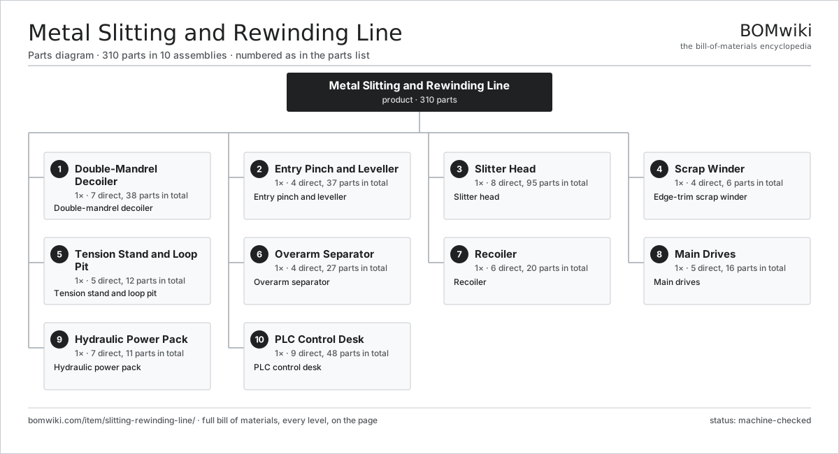
| # | Part | Qty | What it does |
|---|---|---|---|
| 1 | Double-Mandrel Decoiler 7 parts | 1× | Double-mandrel decoiler |
| 2 | Entry Pinch and Leveller 4 parts | 1× | Entry pinch and leveller |
| 3 | Slitter Head 8 parts | 1× | Slitter head |
| 4 | Scrap Winder 4 parts | 1× | Edge-trim scrap winder |
| 5 | Tension Stand and Loop Pit 5 parts | 1× | Tension stand and loop pit |
| 6 | Overarm Separator 4 parts | 1× | Overarm separator |
| 7 | Recoiler 6 parts | 1× | Recoiler |
| 8 | Main Drives 5 parts | 1× | Main drives |
| 9 | Hydraulic Power Pack 7 parts | 1× | Hydraulic power pack |
| 10 | PLC Control Desk 9 parts | 1× | PLC control desk |
3D model
No 3D model yet. Have a CAD file of this? Add a 3D model — STL renders right on this page; STEP, FreeCAD, and OpenSCAD sources are welcome too (openly licensed, like all 3D models on BOMwiki).
Build & assembly graph
expand / collapse · shared sub-assemblies converge · links to related products · est. labourTap an assembly to expand/collapse · tap a part to open it · use “Open page” for any node · drag to pan, scroll to zoom.
Bill of materials for Metal Slitting and Rewinding Line
10 top-level lines · 99 rows shown · 310 parts total · indented to 3 levels| # | Item / sub-assembly | Part no. | Qty/assy | Ext. qty | Parts | Type |
|---|---|---|---|---|---|---|
| 1 | Double-Mandrel Decoiler 7 parts | slitting-rewinding-line-decoiler | 1× | 1 | 38 | assembly |
| 1.1 | Decoiler Turret | slitting-rewinding-line-decoiler-turret | 1× | 1 | · | part |
| 1.2 | Expanding Mandrel 5 parts | slitting-rewinding-line-mandrel | 2× | 2 | 12 | assembly |
| 1.2.1 | Mandrel Shaft | slitting-rewinding-line-mandrel-shaft | 1× | 2 | · | part |
| 1.2.2 | Mandrel Segment | slitting-rewinding-line-mandrel-segment | 4× | 8 | · | part |
| 1.2.3 | Expansion Cylinder | slitting-rewinding-line-mandrel-cylinder | 1× | 2 | · | part |
| 1.2.4 | Wedge Actuator | slitting-rewinding-line-mandrel-wedge | 4× | 8 | · | part |
| 1.2.5 | Ball Bearing | ball-bearing | 2× | 4 | · | part |
| 1.3 | Coil Car 3 parts | slitting-rewinding-line-coil-car | 1× | 1 | 6 | assembly |
| 1.3.1 | Coil Saddle | slitting-rewinding-line-coil-saddle | 1× | 1 | · | part |
| 1.3.2 | Coil Car Lift Cylinder | slitting-rewinding-line-coil-car-lift | 1× | 1 | · | part |
| 1.3.3 | Coil Car Wheel | slitting-rewinding-line-coil-car-wheel | 4× | 4 | · | part |
| 1.4 | Peeler and Threading Table | slitting-rewinding-line-peeler | 1× | 1 | · | part |
| 1.5 | Decoiler Motor | slitting-rewinding-line-decoiler-motor | 1× | 1 | · | part |
| 1.6 | Ball Bearing | ball-bearing | 4× | 4 | · | part |
| 1.7 | Fastener Set | fastener-set | 1× | 1 | · | part |
| 2 | Entry Pinch and Leveller 4 parts | slitting-rewinding-line-entry | 1× | 1 | 37 | assembly |
| 2.1 | Entry Pinch Roll | slitting-rewinding-line-pinch-roll | 2× | 2 | · | part |
| 2.2 | Roller Leveller 4 parts | slitting-rewinding-line-leveller | 1× | 1 | 30 | assembly |
| 2.2.1 | Leveller Work Roll | slitting-rewinding-line-leveller-work-roll | 9× | 9 | · | part |
| 2.2.2 | Leveller Backup Roll | slitting-rewinding-line-leveller-backup-roll | 12× | 12 | · | part |
| 2.2.3 | Leveller Frame | slitting-rewinding-line-leveller-frame | 1× | 1 | · | part |
| 2.2.4 | Ball Bearing | ball-bearing | 8× | 8 | · | part |
| 2.3 | Entry Edge Guide | slitting-rewinding-line-edge-guide | 1× | 1 | · | part |
| 2.4 | Ball Bearing | ball-bearing | 4× | 4 | · | part |
| 3 | Slitter Head 8 parts | slitting-rewinding-line-slitter-head | 1× | 1 | 95 | assembly |
| 3.1 | Arbor Shaft | slitting-rewinding-line-arbor-shaft | 2× | 2 | · | part |
| 3.2 | Circular Slitting Knife | slitting-rewinding-line-circular-knife | 24× | 24 | · | part |
| 3.3 | Arbor Spacer | slitting-rewinding-line-spacer | 40× | 40 | · | part |
| 3.4 | Stripper Ring | slitting-rewinding-line-stripper-ring | 22× | 22 | · | part |
| 3.5 | Knife Cassette | slitting-rewinding-line-cassette | 1× | 1 | · | part |
| 3.6 | Arbor Housing | slitting-rewinding-line-arbor-housing | 1× | 1 | · | part |
| 3.7 | Ball Bearing | ball-bearing | 4× | 4 | · | part |
| 3.8 | Fastener Set | fastener-set | 1× | 1 | · | part |
| 4 | Scrap Winder 4 parts | slitting-rewinding-line-scrap-winder | 1× | 1 | 6 | assembly |
| 4.1 | Scrap Mandrel | slitting-rewinding-line-scrap-mandrel | 1× | 1 | · | part |
| 4.2 | Trim Chute | slitting-rewinding-line-scrap-guide | 2× | 2 | · | part |
| 4.3 | Scrap Winder Motor | slitting-rewinding-line-scrap-motor | 1× | 1 | · | part |
| 4.4 | Ball Bearing | ball-bearing | 2× | 2 | · | part |
| 5 | Tension Stand and Loop Pit 5 parts | slitting-rewinding-line-tension-stand | 1× | 1 | 12 | assembly |
| 5.1 | Bridle Roll | slitting-rewinding-line-bridle-roll | 3× | 3 | · | part |
| 5.2 | Loop Pit | slitting-rewinding-line-loop-pit | 1× | 1 | · | part |
| 5.3 | Felt Tension Pad | slitting-rewinding-line-felt-pad | 1× | 1 | · | part |
| 5.4 | Dancer Roll | slitting-rewinding-line-dancer-roll | 1× | 1 | · | part |
| 5.5 | Ball Bearing | ball-bearing | 6× | 6 | · | part |
| 6 | Overarm Separator 4 parts | slitting-rewinding-line-separator | 1× | 1 | 27 | assembly |
| 6.1 | Overarm Beam | slitting-rewinding-line-overarm | 1× | 1 | · | part |
| 6.2 | Separator Disc | slitting-rewinding-line-separator-disc | 23× | 23 | · | part |
| 6.3 | Separator Shaft | slitting-rewinding-line-separator-shaft | 1× | 1 | · | part |
| 6.4 | Ball Bearing | ball-bearing | 2× | 2 | · | part |
| 7 | Recoiler 6 parts | slitting-rewinding-line-recoiler | 1× | 1 | 20 | assembly |
| 7.1 | Recoiler Mandrel 5 parts | slitting-rewinding-line-recoiler-mandrel | 1× | 1 | 12 | assembly |
| 7.1.1 | Mandrel Shaft | slitting-rewinding-line-mandrel-shaft | 1× | 1 | · | part |
| 7.1.2 | Mandrel Segment | slitting-rewinding-line-mandrel-segment | 4× | 4 | · | part |
| 7.1.3 | Expansion Cylinder | slitting-rewinding-line-mandrel-cylinder | 1× | 1 | · | part |
| 7.1.4 | Wedge Actuator | slitting-rewinding-line-mandrel-wedge | 4× | 4 | · | part |
| 7.1.5 | Ball Bearing | ball-bearing | 2× | 2 | · | part |
| 7.2 | Strip Separator | slitting-rewinding-line-strip-separator | 1× | 1 | · | part |
| 7.3 | Outboard Support | slitting-rewinding-line-outboard-support | 1× | 1 | · | part |
| 7.4 | Pressure Roll | slitting-rewinding-line-tension-pad-roll | 1× | 1 | · | part |
| 7.5 | Recoiler Motor | slitting-rewinding-line-recoiler-motor | 1× | 1 | · | part |
| 7.6 | Ball Bearing | ball-bearing | 4× | 4 | · | part |
| 8 | Main Drives 5 parts | slitting-rewinding-line-drives | 1× | 1 | 16 | assembly |
| 8.1 | Slitter Drive Motor | slitting-rewinding-line-slitter-motor | 1× | 1 | · | part |
| 8.2 | Reduction Gearbox 4 parts | slitting-rewinding-line-gearbox | 1× | 1 | 9 | assembly |
| 8.2.1 | Gearbox Housing | gearbox-housing | 1× | 1 | · | part |
| 8.2.2 | Helical Gear Pair | gear-pair | 2× | 2 | · | part |
| 8.2.3 | Ball Bearing | ball-bearing | 4× | 4 | · | part |
| 8.2.4 | Oil Seal | oil-seal | 2× | 2 | · | part |
| 8.3 | Shaft Coupling | slitting-rewinding-line-coupling | 3× | 3 | · | part |
| 8.4 | Line Shaft | slitting-rewinding-line-line-shaft | 1× | 1 | · | part |
| 8.5 | Drive Belt | drive-belt | 2× | 2 | · | part |
| 9 | Hydraulic Power Pack 7 parts | slitting-rewinding-line-hydraulic-pack | 1× | 1 | 11 | assembly |
| 9.1 | Hydraulic Pump | slitting-rewinding-line-hyd-pump | 1× | 1 | · | part |
| 9.2 | Reservoir Tank | slitting-rewinding-line-hyd-tank | 1× | 1 | · | part |
| 9.3 | Valve Block | slitting-rewinding-line-hyd-valve-block | 1× | 1 | · | part |
| 9.4 | Accumulator | slitting-rewinding-line-hyd-accumulator | 1× | 1 | · | part |
| 9.5 | Service Cylinder | slitting-rewinding-line-hyd-cylinder | 4× | 4 | · | part |
| 9.6 | Pressure Sensor | pressure-sensor | 2× | 2 | · | part |
| 9.7 | O-Ring Set | oring-set | 1× | 1 | · | part |
| 10 | PLC Control Desk 9 parts | slitting-rewinding-line-control-desk | 1× | 1 | 48 | assembly |
| 10.1 | PLC | slitting-rewinding-line-plc | 1× | 1 | · | part |
| 10.2 | Variable-Frequency Drive | slitting-rewinding-line-vfd | 3× | 3 | · | part |
| 10.3 | HMI Touchscreen | slitting-rewinding-line-hmi | 1× | 1 | · | part |
| 10.4 | Tension Controller 4 parts | slitting-rewinding-line-tension-controller | 1× | 1 | 17 | assembly |
| 10.4.1 | Tension Load Cell | slitting-rewinding-line-load-cell | 2× | 2 | · | part |
| 10.4.2 | Control Board 5 parts + deeper › | slitting-rewinding-line-control-pcb | 1× | 1 | 13 | assembly |
| 10.4.3 | Microcontroller | mcu | 1× | 1 | · | part |
| 10.4.4 | SMD Passive (R/C/L) | smd-passives | 1× | 1 | · | part |
| 10.5 | Line Encoder | slitting-rewinding-line-encoder | 3× | 3 | · | part |
| 10.6 | Control Board 5 parts | slitting-rewinding-line-control-pcb | 1× | 1 | 13 | assembly |
| 10.6.1 | Bare PCB | pcb-bare | 1× | 1 | · | part |
| 10.6.2 | Microcontroller | mcu | 1× | 1 | · | part |
| 10.6.3 | SMD Passive (R/C/L) | smd-passives | 1× | 1 | · | part |
| 10.6.4 | Relay | relay | 4× | 4 | · | part |
| 10.6.5 | Connector | connector | 6× | 6 | · | part |
| 10.7 | Power Supply | power-supply | 1× | 1 | · | part |
| 10.8 | Wire Bundle | wire-bundle | 1× | 1 | · | part |
| 10.9 | Connector | connector | 8× | 8 | · | part |
Related products
same domain, ranked by shared parts Bevel Gear Generator
201 parts · shares 4 with this page
Cold Rolling Mill
991 parts · shares 4 with this page
Bevel Gear Generator
201 parts · shares 4 with this page
Cold Rolling Mill
991 parts · shares 4 with this page
 Creep-Feed Grinder
571 parts · shares 4 with this page
Drag Finishing Machine
735 parts · shares 4 with this page
Creep-Feed Grinder
571 parts · shares 4 with this page
Drag Finishing Machine
735 parts · shares 4 with this page
 Industrial Band Saw
131 parts · shares 4 with this page
Multi-Blanking Line
492 parts · shares 4 with this page
Industrial Band Saw
131 parts · shares 4 with this page
Multi-Blanking Line
492 parts · shares 4 with this page
Sourcing: possible vendors
Prices, MOQ, and lead times are algorithmic estimates, not quotes, and not claims about these companies. Company mappings are curated by keyword; est. price band $10k–$1M. How estimates work| Vendor | HQ | Specialty | MOQ | Lead time |
|---|---|---|---|---|
|
🇩🇪DMG MORI
dmgmori.com ↗
|
Bielefeld, DE | Machine tools | 5 units | 12–20 wks |
|
🇯🇵Mazak
mazak.com ↗
|
Oguchi, JP | Machine tools | 5 units | 12–20 wks |
| haascnc.com ↗ | Oxnard, US | CNC machine tools | 5 units | 12–20 wks |
|
🇯🇵Okuma
okuma.com ↗
|
Niwa, JP | Machine tools | 5 units | 12–20 wks |
|
🇩🇪Trumpf
trumpf.com ↗
|
Ditzingen, DE | Laser & sheet-metal machines | 5 units | 12–20 wks |
1,185-word article