Plate Rolling Machine
ProductOverview
A plate rolling machine, also called a plate bending roll, curves flat steel plate into cylinders, cones, and other curved shells by passing it between rotating rolls. A large driven roll grips the plate and feeds it through, while one or more positioning rolls push against it to set the bend radius. Raising the bending rolls more produces a tighter curve, and the plate emerges as a continuous arc. Most heavy machines are three-roll or four-roll designs, named for how many rolls they use to control the bend.
The machine is built on a heavy Main Frame that carries the driven Top Roll and the Side Roll set. A Roll Drive turns the rolls, a Hydraulic Power Pack positions them, and the NC Control coordinates the bend. The Drop-End and Supports handles the finished shell and supports long plate, and the Guarding protects the operator.
How it works
A flat plate is fed in until it sits between the top roll and the side rolls. The Lift Cylinder under each Side Roll raises it, pinching the plate against the Top Roll. The Drive Motor then turns the top roll, which grips the plate by friction and feeds it through. As the plate passes over the raised side roll it is bent past its yield point and takes a permanent curve. The height of the side rolls sets the radius: raise them more for a tighter cylinder, less for a gentle curve.
The leading and trailing ends need special handling. When a plate first enters, a short flat length stays unbent because it has not yet reached the bending roll. To deal with this the machine pre-bends each end, either by clamping it and lifting one roll on a four-roll machine, or by reversing and adjusting on a three-roll machine. Without pre-bending the finished cylinder would have two flat tangent ends that prevent a clean weld seam. Four-roll machines pre-bend both ends in one setup with a separate clamping roll, which is why they are preferred for production work.
On a four-roll machine the Position Encoder on each side roll reports its height to the control, so the operator can dial a radius and have the rolls move to it. A cone is rolled by tilting the side rolls so one end is bent more tightly than the other, producing a tapered curve along the plate.
Subsystems
The Main Frame carries the entire bending reaction. Its two Side Housing plates are tied together by Cross Tie beams and hold the rolls in Bearing Block supports. The frame must stay rigid because any spread between the housings would let the rolls bow and roll an uneven radius.
The Top Roll is the driven, gripping roll. Its Top Roll Barrel is a forged, hardened cylinder running in self-aligning Roll Bearing units on each Roll Journal. The Side Roll barrels are the same construction but lighter, each raised by its lift cylinder. Larger machines use rolls with a slight crown ground into the barrel to compensate for deflection so wide plate bends to a uniform radius across its width.
The Roll Drive supplies torque, not speed. A Drive Motor, usually hydraulic on heavy machines, turns the rolls through a Gearbox Housing with Helical Gear Pair reduction and Roll Coupling connections to each roll journal. The rolls turn slowly, often only a few metres per minute, because the bending load is large.
Hydraulics and control
The Hydraulic Power Pack is the muscle for positioning. Its Hydraulic Pump feeds the lift and drop cylinders through a Valve Manifold, with Pressure Sensor feedback so the control knows the load. The NC Control reads the side-roll encoders and meters the cylinders to hold each roll at its target height. A Control Unit coordinates roll positions and feed, the operator works through an LCD Panel, and a portable Operator Pendant lets the operator jog the rolls while watching the plate curl. Relay outputs switch the heavier interlocked loads and signals run over a Wire Bundle and Connector set.
Handling and safety
Once a cylinder is rolled it surrounds the top roll and cannot be lifted off. The Drop-End and Supports solves this with a Drop-End Yoke yoke that swings down on its Drop-End Cylinder, freeing one end of the top roll so the finished shell slides off. An Overhead Support holds the rising end of the plate as it curls, and Side Support rests keep wide plate from sagging. Safety is handled by the Guarding: pressure-sensitive Safety Trip Bar trips across the roll entry stop the rolls if a hand or sleeve is caught, backed by Emergency Stop buttons that cut all drive power.
Variants and use
Plate rollers range from small initial-pinch three-roll machines that bend light gauge to large four-roll and double-pinch machines that roll plate over 150 mm thick and several metres wide. They are central to fabricating storage tanks, boiler shells, pipe, wind-turbine tower sections, and pressure vessels. The four-roll layout dominates production because it pre-bends both ends and feeds the plate from a fixed reference, giving repeatable cylinders ready for a longitudinal weld, while three-roll machines remain common for thicker single-piece work where setup time matters less.
Plate Rolling Machine parts and their functions
8 top-level parts · 109 parts in total · full bill of materials below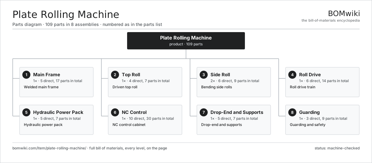
| # | Part | Qty | What it does |
|---|---|---|---|
| 1 | Main Frame 5 parts | 1× | Welded main frame |
| 2 | Top Roll 4 parts | 1× | Driven top roll |
| 3 | Side Roll 6 parts | 2× | Bending side rolls |
| 4 | Roll Drive 6 parts | 1× | Roll drive train |
| 5 | Hydraulic Power Pack 5 parts | 1× | Hydraulic power pack |
| 6 | NC Control 10 parts | 1× | NC control cabinet |
| 7 | Drop-End and Supports 5 parts | 1× | Drop-end and supports |
| 8 | Guarding 3 parts | 1× | Guarding and safety |
3D model
No 3D model yet. Have a CAD file of this? Add a 3D model — STL renders right on this page; STEP, FreeCAD, and OpenSCAD sources are welcome too (openly licensed, like all 3D models on BOMwiki).
Build & assembly graph
expand / collapse · shared sub-assemblies converge · links to related products · est. labourTap an assembly to expand/collapse · tap a part to open it · use “Open page” for any node · drag to pan, scroll to zoom.
Bill of materials for Plate Rolling Machine
8 top-level lines · 52 rows shown · 109 parts total · indented to 3 levels| # | Item / sub-assembly | Part no. | Qty/assy | Ext. qty | Parts | Type |
|---|---|---|---|---|---|---|
| 1 | Main Frame 5 parts | plate-rolling-machine-frame | 1× | 1 | 17 | assembly |
| 1.1 | Side Housing | plate-rolling-machine-side-housing | 2× | 2 | · | part |
| 1.2 | Cross Tie | plate-rolling-machine-cross-tie | 2× | 2 | · | part |
| 1.3 | Bearing Block | plate-rolling-machine-bearing-block | 6× | 6 | · | part |
| 1.4 | Ball Bearing | ball-bearing | 6× | 6 | · | part |
| 1.5 | Fastener Set | fastener-set | 1× | 1 | · | part |
| 2 | Top Roll 4 parts | plate-rolling-machine-top-roll | 1× | 1 | 7 | assembly |
| 2.1 | Top Roll Barrel | plate-rolling-machine-top-roll-barrel | 1× | 1 | · | part |
| 2.2 | Roll Journal | plate-rolling-machine-roll-journal | 2× | 2 | · | part |
| 2.3 | Roll Bearing | plate-rolling-machine-roll-bearing | 2× | 2 | · | part |
| 2.4 | Oil Seal | oil-seal | 2× | 2 | · | part |
| 3 | Side Roll 6 parts | plate-rolling-machine-side-roll | 2× | 2 | 9 | assembly |
| 3.1 | Side Roll Barrel | plate-rolling-machine-side-roll-barrel | 1× | 2 | · | part |
| 3.2 | Roll Journal | plate-rolling-machine-roll-journal | 2× | 4 | · | part |
| 3.3 | Roll Bearing | plate-rolling-machine-roll-bearing | 2× | 4 | · | part |
| 3.4 | Lift Cylinder | plate-rolling-machine-lift-cylinder | 1× | 2 | · | part |
| 3.5 | Position Encoder | plate-rolling-machine-position-encoder | 1× | 2 | · | part |
| 3.6 | Oil Seal | oil-seal | 2× | 4 | · | part |
| 4 | Roll Drive 6 parts | plate-rolling-machine-roll-drive | 1× | 1 | 14 | assembly |
| 4.1 | Drive Motor | plate-rolling-machine-drive-motor | 1× | 1 | · | part |
| 4.2 | Gearbox Housing | gearbox-housing | 1× | 1 | · | part |
| 4.3 | Helical Gear Pair | gear-pair | 3× | 3 | · | part |
| 4.4 | Roll Coupling | plate-rolling-machine-spindle-coupling | 3× | 3 | · | part |
| 4.5 | Ball Bearing | ball-bearing | 4× | 4 | · | part |
| 4.6 | Oil Seal | oil-seal | 2× | 2 | · | part |
| 5 | Hydraulic Power Pack 5 parts | plate-rolling-machine-hydraulic-unit | 1× | 1 | 7 | assembly |
| 5.1 | Hydraulic Pump | plate-rolling-machine-hydraulic-pump | 1× | 1 | · | part |
| 5.2 | Hydraulic Tank | plate-rolling-machine-hydraulic-tank | 1× | 1 | · | part |
| 5.3 | Valve Manifold | plate-rolling-machine-valve-block | 1× | 1 | · | part |
| 5.4 | Pressure Sensor | pressure-sensor | 3× | 3 | · | part |
| 5.5 | O-Ring Set | oring-set | 1× | 1 | · | part |
| 6 | NC Control 10 parts | plate-rolling-machine-control | 1× | 1 | 30 | assembly |
| 6.1 | Control Unit | plate-rolling-machine-control-unit | 1× | 1 | · | part |
| 6.2 | LCD Panel | lcd-panel | 1× | 1 | · | part |
| 6.3 | Power Supply | power-supply | 1× | 1 | · | part |
| 6.4 | Bare PCB | pcb-bare | 1× | 1 | · | part |
| 6.5 | Microcontroller | mcu | 1× | 1 | · | part |
| 6.6 | SMD Passive (R/C/L) | smd-passives | 1× | 1 | · | part |
| 6.7 | Relay | relay | 8× | 8 | · | part |
| 6.8 | Operator Pendant | plate-rolling-machine-pendant | 1× | 1 | · | part |
| 6.9 | Wire Bundle | wire-bundle | 1× | 1 | · | part |
| 6.10 | Connector | connector | 14× | 14 | · | part |
| 7 | Drop-End and Supports 5 parts | plate-rolling-machine-support-arm | 1× | 1 | 7 | assembly |
| 7.1 | Drop-End Yoke | plate-rolling-machine-drop-end | 1× | 1 | · | part |
| 7.2 | Overhead Support | plate-rolling-machine-overhead-support | 1× | 1 | · | part |
| 7.3 | Side Support | plate-rolling-machine-side-support | 2× | 2 | · | part |
| 7.4 | Drop-End Cylinder | plate-rolling-machine-drop-cylinder | 1× | 1 | · | part |
| 7.5 | Ball Bearing | ball-bearing | 2× | 2 | · | part |
| 8 | Guarding 3 parts | plate-rolling-machine-guard | 1× | 1 | 9 | assembly |
| 8.1 | Sheet Metal Panel | sheet-panel | 4× | 4 | · | part |
| 8.2 | Safety Trip Bar | plate-rolling-machine-safety-bar | 2× | 2 | · | part |
| 8.3 | Emergency Stop | plate-rolling-machine-estop | 3× | 3 | · | part |
Related products
same domain, ranked by shared parts Angle Roll Bender
100 parts · shares 5 with this page
Centering and Facing Machine
1,419 parts · shares 5 with this page
CNC Metal Spinning Machine
768 parts · shares 5 with this page
Angle Roll Bender
100 parts · shares 5 with this page
Centering and Facing Machine
1,419 parts · shares 5 with this page
CNC Metal Spinning Machine
768 parts · shares 5 with this page
 Continuous Belt Furnace
130 parts · shares 5 with this page
Continuous Belt Furnace
130 parts · shares 5 with this page
 Creep-Feed Grinder
571 parts · shares 5 with this page
Cut-to-Length Line
500 parts · shares 5 with this page
Creep-Feed Grinder
571 parts · shares 5 with this page
Cut-to-Length Line
500 parts · shares 5 with this page
Sourcing: possible vendors
Prices, MOQ, and lead times are algorithmic estimates, not quotes, and not claims about these companies. Company mappings are curated by keyword; est. price band $10k–$1M. How estimates work| Vendor | HQ | Specialty | MOQ | Lead time |
|---|---|---|---|---|
|
🇩🇪DMG MORI
dmgmori.com ↗
|
Bielefeld, DE | Machine tools | 5 units | 12–20 wks |
|
🇯🇵Mazak
mazak.com ↗
|
Oguchi, JP | Machine tools | 5 units | 12–20 wks |
| haascnc.com ↗ | Oxnard, US | CNC machine tools | 5 units | 12–20 wks |
|
🇯🇵Okuma
okuma.com ↗
|
Niwa, JP | Machine tools | 5 units | 12–20 wks |
|
🇩🇪Trumpf
trumpf.com ↗
|
Ditzingen, DE | Laser & sheet-metal machines | 5 units | 12–20 wks |
990-word article