Bed-Type Milling Machine
ProductOverview
A bed-type milling machine is a heavy, rigid mill in which the worktable moves in only two directions, longitudinally along the bed and crosswise on a saddle, while vertical cutting depth is set by the spindle head rather than by raising the table. This is the defining contrast with a knee mill, where a vertically adjustable knee carries the table up and down. By keeping the table at a fixed height on a solid bed, the bed-type machine gains stiffness and can take heavier cuts, which makes it the standard choice for production milling of larger, heavier parts where a knee mill would flex.
The trade is flexibility for rigidity. A knee mill can quickly raise the table to a small tool or a tall part, which is handy for varied toolroom work. A bed mill gives that up in exchange for a low, heavily supported table that does not droop or shift under load, so it holds accuracy through long roughing passes on big workpieces like plates, frames, and housings.
The machine is built from seven systems. The Bed and Base is the rigid foundation. The Table and Slides move the work in X and Y. The Spindle Head carries the cutting spindle. The Headstock sets vertical position. The Feed Drives move the axes. The Coolant System cools and clears the cut. The Control System commands the machine.
The bed and base
The Bed and Base is what the whole design is named for. The Bed Casting is a heavy, ribbed gray cast iron structure that fixes the table at a constant height and carries the Longitudinal Way guideways running its length. Because the bed does not move, it can be made massive and rigidly supported by the Base Casting beneath it, giving the machine its characteristic stiffness. The guideways are protected by Way Cover panels, and the machine sits on Leveling Foot that anchor it and bring the table level. Cast iron is used throughout because it damps vibration well and machines to a fine reference surface, both essential for a machine that takes heavy interrupted cuts.
Table and saddle
The Table and Slides give the two table motions. The Worktable is a T-slotted cast iron surface that holds workpieces and fixtures, sliding longitudinally along the bed for the X axis. It rides on the Saddle, which itself moves crosswise on the Cross Way guides for the Y axis. Vertical motion is deliberately absent from the table; cutting depth comes from the head instead. This keeps the table low and fully supported by the bed at all times, unlike a knee mill where the table is cantilevered out on a raised knee. A Table Wiper keeps chips off the ways, and a Chip Tray drains coolant and swarf away.
The spindle head
The Spindle Head does the cutting. The Spindle is a hardened shaft running in preloaded Ball Bearing units for low runout, driven by a Spindle Motor of 7.5-30 kW through a multi-speed Gearbox Housing. The geared drive gives high torque at low speed, which heavy roughing of steel and cast iron needs, with a wide speed range from a few dozen rpm up to several thousand. Many bed mills include a Quill, a sliding sleeve that lets the spindle feed vertically a short distance for drilling and fine depth setting without moving the whole head. A Drawbar holds tooling in the Spindle Taper.
Setting vertical position
Because the table does not rise, vertical position is set at the Headstock. The spindle head rides on a Column and is raised or lowered by a Vertical Screw driven by a Servo Motor, moving along the Vertical Way guides. Once set, a Head Clamp locks the head at height so the structure is rigid during cutting rather than relying on the screw to hold position. This arrangement keeps the heavy work fixed and moves only the lighter head, which contributes to the machine's stability under load.
Feed and feedback
The Feed Drives move the table and saddle. On a CNC bed mill each axis uses a Servo Motor turning a ground Ball Screw through a Feed Coupling, with a Linear Scale closing the loop on real table position. A Handwheel remains on each axis for manual setup, a reminder that many bed mills are run as conventional machines with a digital readout rather than full CNC. A Lubrication Pump feeds the ways and screws so they do not run dry under the high contact loads of heavy cutting.
Coolant, chips, and control
The Coolant System floods the cut from a Coolant Pump drawing from the Coolant Tank, aimed by a Coolant Nozzle, with chips cleared by a conveyor. The Control System ranges from a simple digital readout on a manual machine to a full CNC with a CNC Control, a Servo Amplifier per axis, and an Operator Panel, all behind Guarding that protects the operator from chips and coolant.
Use
Bed-type mills sit between flexible knee mills and full machining centers. Shops choose them when parts are too heavy or too large for a knee mill and the work does not need the automatic tool changing of a machining center. Typical jobs are facing and slotting large plates, machining weldments and frames, and roughing castings before they move to a finishing machine. Their rigidity also makes them well suited to retrofitting with CNC, since the solid bed holds accuracy that a programmed toolpath can then exploit.
Bed-Type Milling Machine parts and their functions
7 top-level parts · 151 parts in total · full bill of materials below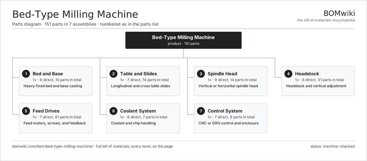
| # | Part | Qty | What it does |
|---|---|---|---|
| 1 | Bed and Base 6 parts | 1× | Heavy fixed bed and base casting |
| 2 | Table and Slides 7 parts | 1× | Longitudinal and cross table slides |
| 3 | Spindle Head 9 parts | 1× | Vertical or horizontal spindle head |
| 4 | Headstock 6 parts | 1× | Headstock and vertical adjustment |
| 5 | Feed Drives 7 parts | 1× | Feed motors, screws, and feedback |
| 6 | Coolant System 6 parts | 1× | Coolant and chip handling |
| 7 | Control System 7 parts | 1× | CNC or DRO control and enclosure |
3D model
No 3D model yet. Have a CAD file of this? Add a 3D model — STL renders right on this page; STEP, FreeCAD, and OpenSCAD sources are welcome too (openly licensed, like all 3D models on BOMwiki).
Build & assembly graph
expand / collapse · shared sub-assemblies converge · links to related products · est. labourTap an assembly to expand/collapse · tap a part to open it · use “Open page” for any node · drag to pan, scroll to zoom.
Bill of materials for Bed-Type Milling Machine
7 top-level lines · 63 rows shown · 151 parts total · indented to 3 levels| # | Item / sub-assembly | Part no. | Qty/assy | Ext. qty | Parts | Type |
|---|---|---|---|---|---|---|
| 1 | Bed and Base 6 parts | btm-bed-base | 1× | 1 | 15 | assembly |
| 1.1 | Bed Casting | btm-bed-casting | 1× | 1 | · | part |
| 1.2 | Base Casting | btm-base-casting | 1× | 1 | · | part |
| 1.3 | Longitudinal Way | btm-longitudinal-way | 2× | 2 | · | part |
| 1.4 | Way Cover | btm-way-cover | 4× | 4 | · | part |
| 1.5 | Leveling Foot | btm-leveling-feet | 6× | 6 | · | part |
| 1.6 | Fastener Set | fastener-set | 1× | 1 | · | part |
| 2 | Table and Slides 7 parts | btm-table-slides | 1× | 1 | 14 | assembly |
| 2.1 | Worktable | btm-worktable | 1× | 1 | · | part |
| 2.2 | Saddle | btm-saddle | 1× | 1 | · | part |
| 2.3 | Cross Way | btm-cross-way | 2× | 2 | · | part |
| 2.4 | Table Wiper | btm-table-wiper | 4× | 4 | · | part |
| 2.5 | Ball Bearing | ball-bearing | 4× | 4 | · | part |
| 2.6 | Chip Tray | btm-chip-tray | 1× | 1 | · | part |
| 2.7 | Fastener Set | fastener-set | 1× | 1 | · | part |
| 3 | Spindle Head 9 parts | btm-spindle-head | 1× | 1 | 14 | assembly |
| 3.1 | Spindle | btm-spindle | 1× | 1 | · | part |
| 3.2 | Spindle Motor | btm-spindle-motor | 1× | 1 | · | part |
| 3.3 | Gearbox Housing | gearbox-housing | 1× | 1 | · | part |
| 3.4 | Helical Gear Pair | gear-pair | 2× | 2 | · | part |
| 3.5 | Quill | btm-quill | 1× | 1 | · | part |
| 3.6 | Spindle Taper | btm-spindle-taper | 1× | 1 | · | part |
| 3.7 | Drawbar | btm-drawbar | 1× | 1 | · | part |
| 3.8 | Ball Bearing | ball-bearing | 4× | 4 | · | part |
| 3.9 | Oil Seal | oil-seal | 2× | 2 | · | part |
| 4 | Headstock 6 parts | btm-headstock | 1× | 1 | 31 | assembly |
| 4.1 | Column | btm-column | 1× | 1 | · | part |
| 4.2 | Vertical Screw | btm-vertical-screw | 1× | 1 | · | part |
| 4.3 | Head Clamp | btm-head-clamp | 1× | 1 | · | part |
| 4.4 | Vertical Way | btm-vertical-way | 2× | 2 | · | part |
| 4.5 | Servo Motor 4 parts | servo-motor | 1× | 1 | 24 | assembly |
| 4.5.1 | Stator Assembly 3 parts + deeper › | stator-assembly | 1× | 1 | 3 | assembly |
| 4.5.2 | Rotor Assembly 4 parts + deeper › | rotor-assembly | 1× | 1 | 19 | assembly |
| 4.5.3 | Encoder | encoder | 1× | 1 | · | part |
| 4.5.4 | Motor Housing | motor-housing | 1× | 1 | · | part |
| 4.6 | Ball Bearing | ball-bearing | 2× | 2 | · | part |
| 5 | Feed Drives 7 parts | btm-feed-drives | 1× | 1 | 61 | assembly |
| 5.1 | Servo Motor 4 parts | servo-motor | 2× | 2 | 24 | assembly |
| 5.1.1 | Stator Assembly 3 parts + deeper › | stator-assembly | 1× | 2 | 3 | assembly |
| 5.1.2 | Rotor Assembly 4 parts + deeper › | rotor-assembly | 1× | 2 | 19 | assembly |
| 5.1.3 | Encoder | encoder | 1× | 2 | · | part |
| 5.1.4 | Motor Housing | motor-housing | 1× | 2 | · | part |
| 5.2 | Ball Screw | ball-screw | 2× | 2 | · | part |
| 5.3 | Feed Coupling | btm-feed-coupling | 2× | 2 | · | part |
| 5.4 | Linear Scale | btm-linear-scale | 2× | 2 | · | part |
| 5.5 | Handwheel | btm-handwheel | 2× | 2 | · | part |
| 5.6 | Lubrication Pump | btm-lube-pump | 1× | 1 | · | part |
| 5.7 | Ball Bearing | ball-bearing | 4× | 4 | · | part |
| 6 | Coolant System 6 parts | btm-coolant-system | 1× | 1 | 7 | assembly |
| 6.1 | Coolant Tank | btm-coolant-tank | 1× | 1 | · | part |
| 6.2 | Coolant Pump | btm-coolant-pump | 1× | 1 | · | part |
| 6.3 | Coolant Nozzle | btm-coolant-nozzle | 2× | 2 | · | part |
| 6.4 | Chip Conveyor | vmc-chip-conveyor | 1× | 1 | · | part |
| 6.5 | Coolant Filter | vmc-coolant-filter | 1× | 1 | · | part |
| 6.6 | O-Ring Set | oring-set | 1× | 1 | · | part |
| 7 | Control System 7 parts | btm-control-system | 1× | 1 | 9 | assembly |
| 7.1 | CNC Control | btm-cnc-control | 1× | 1 | · | part |
| 7.2 | Servo Amplifier | btm-servo-amp | 3× | 3 | · | part |
| 7.3 | Operator Panel | btm-operator-panel | 1× | 1 | · | part |
| 7.4 | Power Supply | power-supply | 1× | 1 | · | part |
| 7.5 | Guarding | btm-guarding | 1× | 1 | · | part |
| 7.6 | LCD Panel | lcd-panel | 1× | 1 | · | part |
| 7.7 | Wire Bundle | wire-bundle | 1× | 1 | · | part |
Related products
same domain, ranked by shared parts Five-Axis Machining Center
168 parts · shares 7 with this page
Five-Axis Machining Center
168 parts · shares 7 with this page
 Vertical Machining Center
195 parts · shares 7 with this page
Vertical Machining Center
195 parts · shares 7 with this page
 Horizontal Machining Center
240 parts · shares 7 with this page
Gantry Milling Machine
198 parts · shares 6 with this page
Horizontal Machining Center
240 parts · shares 7 with this page
Gantry Milling Machine
198 parts · shares 6 with this page
 Bevel Gear Generator
201 parts · shares 6 with this page
Centering and Facing Machine
1,419 parts · shares 6 with this page
Bevel Gear Generator
201 parts · shares 6 with this page
Centering and Facing Machine
1,419 parts · shares 6 with this page
Sourcing: possible vendors
Prices, MOQ, and lead times are algorithmic estimates, not quotes, and not claims about these companies. Company mappings are curated by keyword; est. price band $10k–$1M. How estimates work| Vendor | HQ | Specialty | MOQ | Lead time |
|---|---|---|---|---|
|
🇩🇪DMG MORI
dmgmori.com ↗
|
Bielefeld, DE | Machine tools | 5 units | 12–20 wks |
|
🇯🇵Mazak
mazak.com ↗
|
Oguchi, JP | Machine tools | 5 units | 12–20 wks |
| haascnc.com ↗ | Oxnard, US | CNC machine tools | 5 units | 12–20 wks |
|
🇯🇵Okuma
okuma.com ↗
|
Niwa, JP | Machine tools | 5 units | 12–20 wks |
|
🇩🇪Trumpf
trumpf.com ↗
|
Ditzingen, DE | Laser & sheet-metal machines | 5 units | 12–20 wks |
956-word article