Abrasive Flow Machining Machine
ProductOverview
Abrasive flow machining finishes surfaces that a tool cannot reach. Instead of a wheel or a stone, the abrasive is a thick polymer putty carrying hard grit, and the machine extrudes that putty back and forth through the passages of the part under high pressure. Wherever the putty is squeezed and flows fast, it abrades the wall; wherever it is held back, it does little. By restricting the flow to the passages that matter and masking the rest, the process deburrs cross-holes, radiuses sharp edges, polishes bores and removes the recast layer left by EDM or laser drilling, all in places no cutting tool can enter. It is used on fuel- injector nozzles, hydraulic spools, extrusion dies, turbine blades and intake manifolds, anywhere internal flow quality or burr-free edges decide how the part performs.
This is a two-way machine. The work is sealed between two opposed cylinders by the Frame & Clamp, and the Media Cylinders push a charge of media up through the part and then receive it on the way back down. One full pass each way is a cycle, and finish is metered by how many cycles run at what pressure.
How it works
The abrasive is a Abrasive Media of pliable polymer loaded with silicon- carbide, boron-carbide or diamond grit. At rest it is a stiff putty; under pressure it deforms and flows like a very thick fluid, and as it squeezes through a restriction the grit at its surface scrapes the wall. Removal rises with velocity and pressure, so the same media polishes a wide passage gently and a narrow one hard. That is the lever the process uses: a Flow Restrictor in the tooling speeds the media up where more stock must come off, and a Masking Mandrel blocks areas that must stay untouched. The result is selective, gradual finishing that follows the passage shape exactly because the media takes that shape itself.
The work is clamped by the Clamp Cylinder against the Workholding Tooling, which routes the media only through the target passages and seals every joint against the high pressure. The two Media Piston units then trade the media charge back and forth, each stroke a controlled extrusion at a set pressure.
Hydraulics and pressure control
Media pressure does the cutting, so the Hydraulic Power Pack is built to hold it precisely. A motor-driven Hydraulic Pump feeds a Valve Block that directs oil to the upper or lower media piston and to the clamp, while a Proportional Pressure Valve sets the extrusion pressure to a programmed value. An Accumulator steadies the supply as the heavy media is reversed each stroke, and Pressure Sensor units in both Media Cylinders confirm the media is seeing the pressure the recipe calls for. Because the process is metered by pressure and cycle count rather than by position, the same recipe gives the same finish part after part.
Media temperature
Working the media heats it, and warmer media is softer and less viscous, which changes how it cuts. Left unmanaged, the first parts of a run would finish differently from the last. The Media Temperature System holds the media at a set temperature: a Media Chiller pulls heat out through a Heat Exchanger on the media jackets, and a Media Temperature Probe feeds the control so viscosity, and therefore removal rate, stays constant through a long run.
Tooling
Tooling is what makes a general machine finish a specific part. The Fixture Block locates the work and connects its passages to the media cylinders, the Tooling Seal contains the pressure at the joints, and the Flow Restrictor and Masking Mandrel shape where the media flows fast and where it is blocked. Designing the flow path is most of the engineering: get it right and every targeted edge gets the same radius while masked surfaces stay untouched. Tooling is part-specific, so changeover means swapping the fixtures and loading the recipe for that part.
Use and variants
An operator clamps the part, loads the recipe, and the machine runs the set number of cycles at the set pressure before releasing the clamp. A typical job is deburring the intersection of cross-drilled oil galleries in a hydraulic manifold, where a conventional tool cannot reach the burr at all. This two-way machine extrudes media through the part; one-way machines push media through in a single direction and re-collect it, which suits through-passages, and orbital variants add a small relative motion to work flat and complex surfaces. Across the family the appeal is the same: controlled, repeatable finishing of internal and inaccessible features, with the edge radius and surface finish set by recipe rather than by hand.
Control and safety
The Control sequences clamp, media strokes and chiller, counts cycles and holds pressure, then stops at the metered amount of work and shows the result on the Operator Display. The Enclosure & Guards guards the clamp and media zone, the Interlock Switch blocks a stroke while a door is open, and the Emergency Stop dumps hydraulic pressure and halts the cycle at once.
Abrasive Flow Machining Machine parts and their functions
8 top-level parts · 279 parts in total · full bill of materials below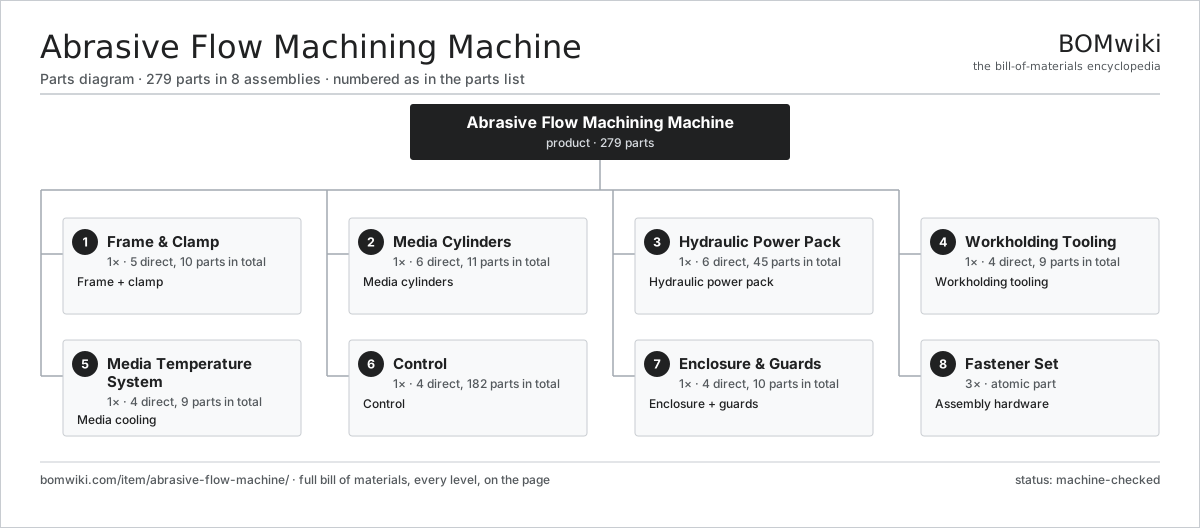
| # | Part | Qty | What it does |
|---|---|---|---|
| 1 | Frame & Clamp 5 parts | 1× | Frame + clamp |
| 2 | Media Cylinders 6 parts | 1× | Media cylinders |
| 3 | Hydraulic Power Pack 6 parts | 1× | Hydraulic power pack |
| 4 | Workholding Tooling 4 parts | 1× | Workholding tooling |
| 5 | Media Temperature System 4 parts | 1× | Media cooling |
| 6 | Control 4 parts | 1× | Control |
| 7 | Enclosure & Guards 4 parts | 1× | Enclosure + guards |
| 8 | Fastener Set | 3× | Assembly hardware |
3D model
No 3D model yet. Have a CAD file of this? Add a 3D model — STL renders right on this page; STEP, FreeCAD, and OpenSCAD sources are welcome too (openly licensed, like all 3D models on BOMwiki).
Build & assembly graph
expand / collapse · shared sub-assemblies converge · links to related products · est. labourTap an assembly to expand/collapse · tap a part to open it · use “Open page” for any node · drag to pan, scroll to zoom.
Bill of materials for Abrasive Flow Machining Machine
8 top-level lines · 63 rows shown · 279 parts total · indented to 3 levels| # | Item / sub-assembly | Part no. | Qty/assy | Ext. qty | Parts | Type |
|---|---|---|---|---|---|---|
| 1 | Frame & Clamp 5 parts | afm-frame | 1× | 1 | 10 | assembly |
| 1.1 | Frame Weldment | afm-frame-weldment | 1× | 1 | · | part |
| 1.2 | Clamp Cylinder 2 parts | afm-clamp-cylinder | 1× | 1 | · | part |
| 1.2.1 | O-Ring Set | oring-set | 2× | 2 | · | part |
| 1.2.2 | Oil Seal | oil-seal | 1× | 1 | · | part |
| 1.3 | Clamp Platen | afm-platen | 2× | 2 | · | part |
| 1.4 | Linear Guide Rail | linear-guide | 2× | 2 | · | part |
| 1.5 | Fastener Set | fastener-set | 2× | 2 | · | part |
| 2 | Media Cylinders 6 parts | afm-media-cylinders | 1× | 1 | 11 | assembly |
| 2.1 | Upper Media Cylinder | afm-upper-cylinder | 1× | 1 | · | part |
| 2.2 | Lower Media Cylinder | afm-lower-cylinder | 1× | 1 | · | part |
| 2.3 | Media Piston | afm-media-piston | 2× | 2 | · | part |
| 2.4 | Piston Seal | afm-piston-seal | 4× | 4 | · | part |
| 2.5 | Pressure Sensor | pressure-sensor | 2× | 2 | · | part |
| 2.6 | Abrasive Media | afm-media-charge | 1× | 1 | · | part |
| 3 | Hydraulic Power Pack 6 parts | afm-hydraulic-pack | 1× | 1 | 45 | assembly |
| 3.1 | Hydraulic Pump 6 parts | afm-hyd-pump | 1× | 1 | 27 | assembly |
| 3.1.1 | Stator Assembly 3 parts + deeper › | stator-assembly | 1× | 1 | 3 | assembly |
| 3.1.2 | Rotor Assembly 4 parts + deeper › | rotor-assembly | 1× | 1 | 19 | assembly |
| 3.1.3 | Motor Housing | motor-housing | 1× | 1 | · | part |
| 3.1.4 | Ball Bearing | ball-bearing | 2× | 2 | · | part |
| 3.1.5 | Oil Seal | oil-seal | 1× | 1 | · | part |
| 3.1.6 | Pump Element | afm-pump-element | 1× | 1 | · | part |
| 3.2 | Oil Reservoir | afm-reservoir | 1× | 1 | · | part |
| 3.3 | Valve Block 3 parts | afm-valve-block | 1× | 1 | 14 | assembly |
| 3.3.1 | Solenoid Valve | afm-solenoid-valve | 4× | 4 | · | part |
| 3.3.2 | Relay | relay | 4× | 4 | · | part |
| 3.3.3 | O-Ring Set | oring-set | 6× | 6 | · | part |
| 3.4 | Accumulator | afm-accumulator | 1× | 1 | · | part |
| 3.5 | Return Filter | afm-hyd-filter | 1× | 1 | · | part |
| 3.6 | Proportional Pressure Valve | afm-prop-valve | 1× | 1 | · | part |
| 4 | Workholding Tooling 4 parts | afm-tooling-station | 1× | 1 | 9 | assembly |
| 4.1 | Fixture Block | afm-fixture-block | 2× | 2 | · | part |
| 4.2 | Flow Restrictor | afm-restrictor | 2× | 2 | · | part |
| 4.3 | Masking Mandrel | afm-mandrel | 1× | 1 | · | part |
| 4.4 | Tooling Seal | afm-tooling-seal | 4× | 4 | · | part |
| 5 | Media Temperature System 4 parts | afm-media-temp-system | 1× | 1 | 9 | assembly |
| 5.1 | Media Chiller 3 parts | afm-media-chiller | 1× | 1 | 3 | assembly |
| 5.1.1 | Compressor | afm-compressor | 1× | 1 | · | part |
| 5.1.2 | Condenser | afm-condenser | 1× | 1 | · | part |
| 5.1.3 | Condenser Fan | afm-chiller-fan | 1× | 1 | · | part |
| 5.2 | Heat Exchanger | afm-heat-exchanger | 1× | 1 | · | part |
| 5.3 | Media Temperature Probe | afm-temp-probe | 1× | 1 | · | part |
| 5.4 | Coolant Hose | afm-coolant-hose | 4× | 4 | · | part |
| 6 | Control 4 parts | afm-control | 1× | 1 | 182 | assembly |
| 6.1 | PLC Controller 4 parts | afm-controller | 1× | 1 | 128 | assembly |
| 6.1.1 | Bare PCB | pcb-bare | 1× | 1 | · | part |
| 6.1.2 | Microcontroller | mcu | 1× | 1 | · | part |
| 6.1.3 | Relay | relay | 6× | 6 | · | part |
| 6.1.4 | SMD Passive (R/C/L) | smd-passives | 120× | 120 | · | part |
| 6.2 | Operator Display 4 parts | afm-display | 1× | 1 | 43 | assembly |
| 6.2.1 | Bare PCB | pcb-bare | 1× | 1 | · | part |
| 6.2.2 | LCD Panel | lcd-panel | 1× | 1 | · | part |
| 6.2.3 | Touch Digitizer | touch-digitizer | 1× | 1 | · | part |
| 6.2.4 | SMD Passive (R/C/L) | smd-passives | 40× | 40 | · | part |
| 6.3 | Wire Bundle | wire-bundle | 1× | 1 | · | part |
| 6.4 | Connector | connector | 10× | 10 | · | part |
| 7 | Enclosure & Guards 4 parts | afm-enclosure | 1× | 1 | 10 | assembly |
| 7.1 | Sheet Metal Panel | sheet-panel | 6× | 6 | · | part |
| 7.2 | Access Door | afm-access-door | 1× | 1 | · | part |
| 7.3 | Interlock Switch | afm-interlock-switch | 2× | 2 | · | part |
| 7.4 | Emergency Stop | afm-estop | 1× | 1 | · | part |
| 8 | Fastener Set | fastener-set | 3× | 3 | · | part |
Related products
same domain, ranked by shared parts Compression Spring Coiler
1,167 parts · shares 4 with this page
Compression Spring Coiler
1,167 parts · shares 4 with this page
Sourcing: possible vendors
Prices, MOQ, and lead times are algorithmic estimates, not quotes, and not claims about these companies. Company mappings are curated by keyword; est. price band $10k–$1M. How estimates work| Vendor | HQ | Specialty | MOQ | Lead time |
|---|---|---|---|---|
|
🇩🇪DMG MORI
dmgmori.com ↗
|
Bielefeld, DE | Machine tools | 5 units | 12–20 wks |
|
🇯🇵Mazak
mazak.com ↗
|
Oguchi, JP | Machine tools | 5 units | 12–20 wks |
| haascnc.com ↗ | Oxnard, US | CNC machine tools | 5 units | 12–20 wks |
|
🇯🇵Okuma
okuma.com ↗
|
Niwa, JP | Machine tools | 5 units | 12–20 wks |
|
🇩🇪Trumpf
trumpf.com ↗
|
Ditzingen, DE | Laser & sheet-metal machines | 5 units | 12–20 wks |
866-word article