Transfer Stamping System
ProductOverview
A transfer stamping system is a mechanical press that runs several separate forming operations in one machine and uses a mechanical transfer mechanism to carry each part from one die to the next. A flat blank is fed in at one end, and after passing through a line of die stations it leaves as a finished pressed part such as an oil pan, a structural bracket, a wheel half, or an appliance shell. The machine does the work of what would otherwise be a row of single presses plus the loaders and conveyors between them, in one frame on one cycle.
The system is built around the Stamping Press, which supplies the forming force, and the Transfer Mechanism, which moves the parts. Blanks enter through the Destacker, pass through the Transfer Die Set with the help of any Idle Station reorientation, and leave on the Part Unloader. The Die Change System system swaps the whole tooling line for a new part, and the Control System keeps every motion locked to the slide.
How the transfer differs from a progressive die
This is the point that sets the machine apart. In a progressive die the part stays attached to a continuous strip of coil stock, and the strip itself indexes forward through one large die one pitch per stroke. The carrier is the metal. In a transfer system there is no strip. The blank is cut loose first, and discrete loose parts are physically picked up and walked through the line by the Transfer Mechanism. The carrier is the machine.
That difference is why transfer suits large, deep, or three-dimensional parts. A deep-drawn shell cannot be left hanging on a strip, and trimming away a strip carrier on a big panel wastes too much metal. Carrying loose blanks also frees each station to be a complete part, so the dies can be turned over and worked on more than one face, which a progressive die cannot do. The cost is mechanical complexity: the transfer must place every part within a fraction of a millimetre, every stroke, in time with a slide that does not wait.
The press
The Stamping Press is a straight-side mechanical press. A motor spins the heavy Flywheel, storing energy that the Clutch-Brake Unit releases into the Eccentric Drive for each stroke. The eccentric shaft drives the Slide down through two Connecting Rod links, and all die stations close at once because they all hang from the same slide. The Bolster takes the load below, the Slide Gib ways hold the slide square under the off-centre loads that come from working several stations of different force at once, and Counterbalance Cylinder cylinders offset the slide weight. The Tie Rod members clamp the frame so it stays stiff at full tonnage. A press in this class runs 630 to 1600 tonnes at 15 to 40 strokes a minute.
The three-axis transfer
The transfer is the defining subsystem. Two Transfer Rail beams run the length of the die line, one on each side, carrying Finger Tooling set at the station pitch. The motion has three axes. The Clamp Drive moves the rails together so the Gripper Finger sets pinch each part. The Lift Drive raises the rails so the parts clear the lower dies. The Advance Drive moves the rails one station downstream, the rails lower to set the parts in the next dies, unclamp, and return empty for the next stroke. Edge-gripped parts use fingers; flat or faced parts ride on Vacuum Cup tooling and locate in a Part Nest.
The rails must never be over a die while the slide is down. The Sync Cam reads the press angle and feeds it to the transfer servos so the motion profile stays clear of the closing dies. Older machines drove the three axes off mechanical cams geared to the crankshaft; servo machines use a Servo Cam Box box per axis, which lets the curves be retuned for a new die set from the control screen.
Blank feeding and die stations
Blanks start as a stack of precut sheets. The Destacker lifts one at a time with its Vacuum Head, while a Magnetic Fanner and a Sheet Separator keep two sheets from coming up together, checked by a Double-Blank Detector. The Stack Lift raises the pile so the top sheet stays at pickup height.
The Transfer Die Set is a line of single-purpose dies. A typical order is draw, trim, pierce, flange, restrike. The Draw Die forms the flat blank into a shell over a Draw Punch while a Binder Ring controls metal flow. Later stations Trim Die, Pierce Die, and Flange Die cut and bend, and the Restrike Die coins the part to final form. A Die Cushion under the bed supplies blank-holder and knockout force. Where the part must be worked on a new face an Idle Station flips it with a Rotary Actuator before the rails pick it up again.
Materials, variants, and use
The press frame and slide are cast steel, the eccentric shaft is forged alloy steel, and die working surfaces are tool steel, often coated for the abrasive high-strength grades. The system runs mild, high-strength low-alloy, and stainless steels and aluminium from about 0.6 to 3.0 mm. Variants split mainly on the transfer drive, mechanical cam versus servo, and on bed size and station count, from compact four-station lines to long eight-station automotive lines.
Changeover speed is what keeps the machine economical, so a Die Change System system with a Moving Bolster rolls the whole die line out and a preset one in, clamped by Die Clamp units. The Part Unloader carries finished parts out on its conveyor. The Control System ties it together: the Line PLC times the cycle, the Servo Drive units run the transfer axes, the Die Protection Module module stops the slide on a mislocated part, and Light Curtain guards protect the operator. These machines run automotive body and chassis pressings, appliance panels, and large housings, the medium-to-high volume parts too big or too deep for a progressive die.
Transfer Stamping System parts and their functions
8 top-level parts · 381 parts in total · full bill of materials below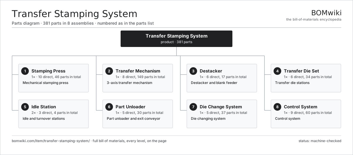
| # | Part | Qty | What it does |
|---|---|---|---|
| 1 | Stamping Press 10 parts | 1× | Mechanical stamping press |
| 2 | Transfer Mechanism 8 parts | 1× | 3-axis transfer mechanism |
| 3 | Destacker 6 parts | 1× | Destacker and blank feeder |
| 4 | Transfer Die Set 6 parts | 1× | Transfer die stations |
| 5 | Idle Station 3 parts | 2× | Idle and turnover stations |
| 6 | Part Unloader 5 parts | 1× | Part unloader and exit conveyor |
| 7 | Die Change System 5 parts | 1× | Die changing system |
| 8 | Control System 9 parts | 1× | Control system |
3D model
No 3D model yet. Have a CAD file of this? Add a 3D model — STL renders right on this page; STEP, FreeCAD, and OpenSCAD sources are welcome too (openly licensed, like all 3D models on BOMwiki).
Build & assembly graph
expand / collapse · shared sub-assemblies converge · links to related products · est. labourTap an assembly to expand/collapse · tap a part to open it · use “Open page” for any node · drag to pan, scroll to zoom.
Bill of materials for Transfer Stamping System
8 top-level lines · 111 rows shown · 381 parts total · indented to 3 levels| # | Item / sub-assembly | Part no. | Qty/assy | Ext. qty | Parts | Type |
|---|---|---|---|---|---|---|
| 1 | Stamping Press 10 parts | transfer-stamping-system-press | 1× | 1 | 46 | assembly |
| 1.1 | Crown | transfer-stamping-system-crown | 1× | 1 | · | part |
| 1.2 | Slide | transfer-stamping-system-slide | 1× | 1 | · | part |
| 1.3 | Bolster | transfer-stamping-system-bolster | 1× | 1 | · | part |
| 1.4 | Eccentric Drive 5 parts | transfer-stamping-system-eccentric-drive | 1× | 1 | 14 | assembly |
| 1.4.1 | Eccentric Shaft | transfer-stamping-system-eccentric-shaft | 1× | 1 | · | part |
| 1.4.2 | Main Gear | transfer-stamping-system-main-gear | 2× | 2 | · | part |
| 1.4.3 | Drive Pinion | transfer-stamping-system-pinion | 1× | 1 | · | part |
| 1.4.4 | Ball Bearing | ball-bearing | 6× | 6 | · | part |
| 1.4.5 | Oil Seal | oil-seal | 4× | 4 | · | part |
| 1.5 | Flywheel | transfer-stamping-system-flywheel | 1× | 1 | · | part |
| 1.6 | Clutch-Brake Unit 5 parts | transfer-stamping-system-clutch-brake | 1× | 1 | 16 | assembly |
| 1.6.1 | Clutch Plate | transfer-stamping-system-clutch-plate | 4× | 4 | · | part |
| 1.6.2 | Brake Plate | transfer-stamping-system-brake-plate | 2× | 2 | · | part |
| 1.6.3 | Engage Cylinder | transfer-stamping-system-air-cylinder | 1× | 1 | · | part |
| 1.6.4 | Rotary Union | transfer-stamping-system-rotary-union | 1× | 1 | · | part |
| 1.6.5 | Coil Spring | coil-spring | 8× | 8 | · | part |
| 1.7 | Slide Gib | transfer-stamping-system-gib | 4× | 4 | · | part |
| 1.8 | Connecting Rod | transfer-stamping-system-connecting-rod | 2× | 2 | · | part |
| 1.9 | Counterbalance Cylinder | transfer-stamping-system-counterbalance | 2× | 2 | · | part |
| 1.10 | Tie Rod | transfer-stamping-system-tie-rod | 4× | 4 | · | part |
| 2 | Transfer Mechanism 8 parts | transfer-stamping-system-transfer-mechanism | 1× | 1 | 149 | assembly |
| 2.1 | Transfer Rail | transfer-stamping-system-transfer-rail | 2× | 2 | · | part |
| 2.2 | Finger Tooling 4 parts | transfer-stamping-system-finger-tooling | 1× | 1 | 48 | assembly |
| 2.2.1 | Gripper Finger | transfer-stamping-system-gripper-finger | 16× | 16 | · | part |
| 2.2.2 | Vacuum Cup | transfer-stamping-system-vacuum-cup | 8× | 8 | · | part |
| 2.2.3 | Finger Mount | transfer-stamping-system-finger-mount | 16× | 16 | · | part |
| 2.2.4 | Part Nest | transfer-stamping-system-part-nest | 8× | 8 | · | part |
| 2.3 | Clamp Drive 4 parts | transfer-stamping-system-clamp-drive | 1× | 1 | 30 | assembly |
| 2.3.1 | Servo Motor 4 parts + deeper › | servo-motor | 1× | 1 | 24 | assembly |
| 2.3.2 | Ball Screw | ball-screw | 2× | 2 | · | part |
| 2.3.3 | Linear Guide Rail | linear-guide | 2× | 2 | · | part |
| 2.3.4 | Clamp Bracket | transfer-stamping-system-clamp-bracket | 2× | 2 | · | part |
| 2.4 | Lift Drive 4 parts | transfer-stamping-system-lift-drive | 1× | 1 | 31 | assembly |
| 2.4.1 | Servo Motor 4 parts + deeper › | servo-motor | 1× | 1 | 24 | assembly |
| 2.4.2 | Ball Screw | ball-screw | 2× | 2 | · | part |
| 2.4.3 | Linear Guide Rail | linear-guide | 4× | 4 | · | part |
| 2.4.4 | Lift Frame | transfer-stamping-system-lift-frame | 1× | 1 | · | part |
| 2.5 | Advance Drive 4 parts | transfer-stamping-system-advance-drive | 1× | 1 | 31 | assembly |
| 2.5.1 | Servo Motor 4 parts + deeper › | servo-motor | 1× | 1 | 24 | assembly |
| 2.5.2 | Helical Gear Pair | gear-pair | 1× | 1 | · | part |
| 2.5.3 | Linear Guide Rail | linear-guide | 4× | 4 | · | part |
| 2.5.4 | Feed Rack | transfer-stamping-system-feed-rack | 2× | 2 | · | part |
| 2.6 | Servo Cam Box | transfer-stamping-system-servo-cam | 2× | 2 | · | part |
| 2.7 | Rail Support | transfer-stamping-system-rail-support | 4× | 4 | · | part |
| 2.8 | Sync Cam | transfer-stamping-system-sync-cam | 1× | 1 | · | part |
| 3 | Destacker 6 parts | transfer-stamping-system-destacker | 1× | 1 | 17 | assembly |
| 3.1 | Vacuum Head 3 parts | transfer-stamping-system-vacuum-head | 1× | 1 | 11 | assembly |
| 3.1.1 | Pickup Cup | transfer-stamping-system-pickup-cup | 8× | 8 | · | part |
| 3.1.2 | Venturi | transfer-stamping-system-venturi | 2× | 2 | · | part |
| 3.1.3 | Drive Belt | drive-belt | 1× | 1 | · | part |
| 3.2 | Magnetic Fanner | transfer-stamping-system-magnetic-fanner | 2× | 2 | · | part |
| 3.3 | Sheet Separator | transfer-stamping-system-sheet-separator | 1× | 1 | · | part |
| 3.4 | Feed Belt | transfer-stamping-system-feed-belt | 1× | 1 | · | part |
| 3.5 | Stack Lift | transfer-stamping-system-stack-lift | 1× | 1 | · | part |
| 3.6 | Double-Blank Detector | transfer-stamping-system-double-blank-detector | 1× | 1 | · | part |
| 4 | Transfer Die Set 6 parts | transfer-stamping-system-die-set | 1× | 1 | 34 | assembly |
| 4.1 | Draw Die 4 parts | transfer-stamping-system-draw-die | 1× | 1 | 8 | assembly |
| 4.1.1 | Die Shoe | transfer-stamping-system-die-shoe | 2× | 2 | · | part |
| 4.1.2 | Draw Punch | transfer-stamping-system-draw-punch | 1× | 1 | · | part |
| 4.1.3 | Binder Ring | transfer-stamping-system-binder-ring | 1× | 1 | · | part |
| 4.1.4 | Guide Post | transfer-stamping-system-guide-post | 4× | 4 | · | part |
| 4.2 | Trim Die | transfer-stamping-system-trim-die | 1× | 1 | · | part |
| 4.3 | Pierce Die | transfer-stamping-system-pierce-die | 1× | 1 | · | part |
| 4.4 | Flange Die | transfer-stamping-system-flange-die | 1× | 1 | · | part |
| 4.5 | Restrike Die | transfer-stamping-system-restrike-die | 1× | 1 | · | part |
| 4.6 | Die Cushion 3 parts | transfer-stamping-system-die-cushion | 2× | 2 | 11 | assembly |
| 4.6.1 | Cushion Cylinder | transfer-stamping-system-cushion-cylinder | 1× | 2 | · | part |
| 4.6.2 | Cushion Pin | transfer-stamping-system-cushion-pin | 8× | 16 | · | part |
| 4.6.3 | Pressure Sensor | pressure-sensor | 2× | 4 | · | part |
| 5 | Idle Station 3 parts | transfer-stamping-system-idle-station | 2× | 2 | 4 | assembly |
| 5.1 | Turnover Gripper | transfer-stamping-system-turnover-gripper | 2× | 4 | · | part |
| 5.2 | Rotary Actuator | transfer-stamping-system-rotary-actuator | 1× | 2 | · | part |
| 5.3 | Shuttle Nest | transfer-stamping-system-shuttle-nest | 1× | 2 | · | part |
| 6 | Part Unloader 5 parts | transfer-stamping-system-unloader | 1× | 1 | 30 | assembly |
| 6.1 | Exit Chute | transfer-stamping-system-exit-chute | 1× | 1 | · | part |
| 6.2 | Exit Conveyor | transfer-stamping-system-exit-conveyor | 1× | 1 | · | part |
| 6.3 | Part Sensor | transfer-stamping-system-part-sensor | 2× | 2 | · | part |
| 6.4 | Drive Belt | drive-belt | 2× | 2 | · | part |
| 6.5 | Servo Motor 4 parts | servo-motor | 1× | 1 | 24 | assembly |
| 6.5.1 | Stator Assembly 3 parts + deeper › | stator-assembly | 1× | 1 | 3 | assembly |
| 6.5.2 | Rotor Assembly 4 parts + deeper › | rotor-assembly | 1× | 1 | 19 | assembly |
| 6.5.3 | Encoder | encoder | 1× | 1 | · | part |
| 6.5.4 | Motor Housing | motor-housing | 1× | 1 | · | part |
| 7 | Die Change System 5 parts | transfer-stamping-system-die-change | 1× | 1 | 37 | assembly |
| 7.1 | Moving Bolster | transfer-stamping-system-moving-bolster | 1× | 1 | · | part |
| 7.2 | Die Clamp | transfer-stamping-system-die-clamp | 8× | 8 | · | part |
| 7.3 | Die Lifter | transfer-stamping-system-die-lifter | 6× | 6 | · | part |
| 7.4 | Bolster Roller | transfer-stamping-system-bolster-roller | 8× | 8 | · | part |
| 7.5 | Hydraulic Power Unit 6 parts | transfer-stamping-system-hydraulic-power-unit | 1× | 1 | 14 | assembly |
| 7.5.1 | Hydraulic Pump | transfer-stamping-system-hydraulic-pump | 1× | 1 | · | part |
| 7.5.2 | Hydraulic Valve | transfer-stamping-system-hydraulic-valve | 6× | 6 | · | part |
| 7.5.3 | Accumulator | transfer-stamping-system-accumulator | 2× | 2 | · | part |
| 7.5.4 | Oil Reservoir | transfer-stamping-system-oil-tank | 1× | 1 | · | part |
| 7.5.5 | O-Ring Set | oring-set | 1× | 1 | · | part |
| 7.5.6 | Pressure Sensor | pressure-sensor | 3× | 3 | · | part |
| 8 | Control System 9 parts | transfer-stamping-system-control | 1× | 1 | 60 | assembly |
| 8.1 | Line PLC | transfer-stamping-system-plc | 1× | 1 | · | part |
| 8.2 | Servo Drive | transfer-stamping-system-servo-drive | 3× | 3 | · | part |
| 8.3 | Die Protection Module | transfer-stamping-system-die-protection | 1× | 1 | · | part |
| 8.4 | Light Curtain | transfer-stamping-system-light-curtain | 4× | 4 | · | part |
| 8.5 | Operator HMI | transfer-stamping-system-hmi | 1× | 1 | · | part |
| 8.6 | I/O Control Board 5 parts | transfer-stamping-system-control-board | 1× | 1 | 23 | assembly |
| 8.6.1 | Bare PCB | pcb-bare | 1× | 1 | · | part |
| 8.6.2 | Microcontroller | mcu | 1× | 1 | · | part |
| 8.6.3 | SMD Passive (R/C/L) | smd-passives | 1× | 1 | · | part |
| 8.6.4 | Relay | relay | 8× | 8 | · | part |
| 8.6.5 | Connector | connector | 12× | 12 | · | part |
| 8.7 | Power Supply | power-supply | 1× | 1 | · | part |
| 8.8 | Wire Bundle | wire-bundle | 2× | 2 | · | part |
| 8.9 | Connector | connector | 24× | 24 | · | part |
Related products
same domain, ranked by shared parts Bevel Gear Generator
201 parts · shares 7 with this page
Bevel Gear Generator
201 parts · shares 7 with this page
 Crankshaft Grinder
511 parts · shares 7 with this page
Crankshaft Grinder
511 parts · shares 7 with this page
 Creep-Feed Grinder
571 parts · shares 7 with this page
Creep-Feed Grinder
571 parts · shares 7 with this page
 Railway Wheel Lathe
1,201 parts · shares 7 with this page
Railway Wheel Lathe
1,201 parts · shares 7 with this page
 Rotary-Table Surface Grinder
172 parts · shares 7 with this page
Camshaft Grinder
489 parts · shares 6 with this page
Rotary-Table Surface Grinder
172 parts · shares 7 with this page
Camshaft Grinder
489 parts · shares 6 with this page
Sourcing: possible vendors
Prices, MOQ, and lead times are algorithmic estimates, not quotes, and not claims about these companies. Company mappings are curated by keyword; est. price band $10k–$1M. How estimates work| Vendor | HQ | Specialty | MOQ | Lead time |
|---|---|---|---|---|
|
🇩🇪DMG MORI
dmgmori.com ↗
|
Bielefeld, DE | Machine tools | 5 units | 12–20 wks |
|
🇯🇵Mazak
mazak.com ↗
|
Oguchi, JP | Machine tools | 5 units | 12–20 wks |
| haascnc.com ↗ | Oxnard, US | CNC machine tools | 5 units | 12–20 wks |
|
🇯🇵Okuma
okuma.com ↗
|
Niwa, JP | Machine tools | 5 units | 12–20 wks |
|
🇩🇪Trumpf
trumpf.com ↗
|
Ditzingen, DE | Laser & sheet-metal machines | 5 units | 12–20 wks |
1,178-word article