Gantry Milling Machine
ProductOverview
A gantry milling machine is a large bridge-type mill built to cut workpieces that are too big for any column or knee machine. Instead of moving the table under a fixed spindle, the spindle rides on a bridge that travels the length of a long stationary bed, so the heavy workpiece stays put while the cutting head comes to it. This layout suits parts measured in meters: machine tool beds, die and mold blocks, ship and turbine castings, aircraft wing structures, and large weldments. Bed lengths of several meters are common, and the largest gantry mills span work weighing many tonnes.
The reason for the gantry layout is simple. A workpiece weighing tens of tonnes cannot be moved around on a sliding table, so the machine moves the small thing, the spindle, over the large thing, the part. A bridge supported on both sides is also far stiffer than a single overhanging column, which matters when the spindle reaches into the middle of a wide part.
The machine is built from eight systems. The Bed and Rails form the long foundation. The Gantry Bridge spans and traverses the bed. The Crossrail and Ram carries the head across and up and down. The Milling Head does the cutting. The Feed Drive System feeds every axis. The Tool and Head System handles tools and heads. The Coolant and Chip System system clears the swarf. The Control Cabinet coordinates the axes.
The bed and rails
The Bed and Rails are the largest structure in the machine. Because a single casting that long is impractical, the bed is built from several Bed Section castings or steel weldments bolted and dowelled end to end on a reinforced concrete foundation, set and grouted with a Foundation Anchor Set. Along the bed run two ground X Rail guides that the gantry rides on, and a Drive Rack on each side for the drive pinions. The top of the bed carries a T-Slot Table surface where large workpieces are clamped directly. Foundation work is a real part of installing a gantry mill: the floor must carry both the machine and the part without settling.
The moving gantry
The Gantry Bridge is a portal that straddles the bed. Two Bridge Upright legs carry a box-section Crossbeam, and the assembly rides the X rails on X Truck roller trucks. The X axis is driven by a X Drive Pinion on each side meshing the bed rack through a Helical Gear Pair reduction. Because the bridge is wide and the travel is long, the two side drives must be kept synchronized; if one side leads the other, the bridge skews and the cut goes off. The control treats X as a master-slave or twin drive to hold the bridge square along the whole bed.
Crossrail, ram, and head
The Crossrail and Ram gives the other two axes. The Saddle rides the Crossrail across the gantry on the Y axis driven by the Y Ball Screw, and the vertical Ram slides up and down for Z on the Z Ball Screw. Because the ram and head are heavy, a Counterbalance Cylinder cylinder supports their weight so the Z drive only has to handle cutting force, not the dead weight. On the largest machines the crossrail can itself be raised on the uprights to clear a tall workpiece before being clamped at a new height.
The Milling Head mounts on the ram. Its Head Body houses a heavy Milling Spindle driven by a Head Motor of 22-55 kW through a multi-speed Gearbox Housing, delivering the torque to push a large face mill through cast iron. A Power Drawbar holds tooling in the Spindle Taper. A defining feature of flexible gantry mills is interchangeable heads: the same ram can carry a straight vertical head, a right-angle head for cutting vertical surfaces, or a universal head that swivels to any angle.
Drives and feedback
The Feed Drive System uses a Servo Motor on each drive, four in all counting the twin X drives. Position feedback comes from a long X Linear Scale running the bed length and Y/Z Linear Scale units on the cross and vertical axes, so the control reads true position rather than inferring it from screw or pinion rotation. A Lubrication System meters oil to the long guideways, screws, and pinion meshes that would otherwise wear quickly under the loads involved.
Tools, heads, coolant, and chips
The Tool and Head System holds 40-80 tools in a floor-standing Tool Magazine served by a Tool Change Arm. On head-changing machines a Head Store rack holds spare heads, and a powered Head Coupler locates, clamps, and drives whichever head the program calls. Cutting big parts makes enormous chip volumes, so the Coolant and Chip System system pairs a large Coolant Tank of up to 3,000 liters with a Bed Chip Conveyor that runs the full bed length to haul swarf away continuously.
Control and use
The Control Cabinet holds the CNC and the Servo Amplifier drives. The CNC Control synchronizes the twin X drives and manages head changes, while a portable Operator Pendant lets the operator set up and jog from anywhere around the large machine. Gantry mills are the standard tool for heavy industry: machine tool builders use them to cut their own beds and columns, mold shops use them for large die blocks, and aerospace and energy makers use them for big structural and turbine parts. They trade the speed and compactness of smaller machines for the sheer size of work they can handle.
Gantry Milling Machine parts and their functions
8 top-level parts · 198 parts in total · full bill of materials below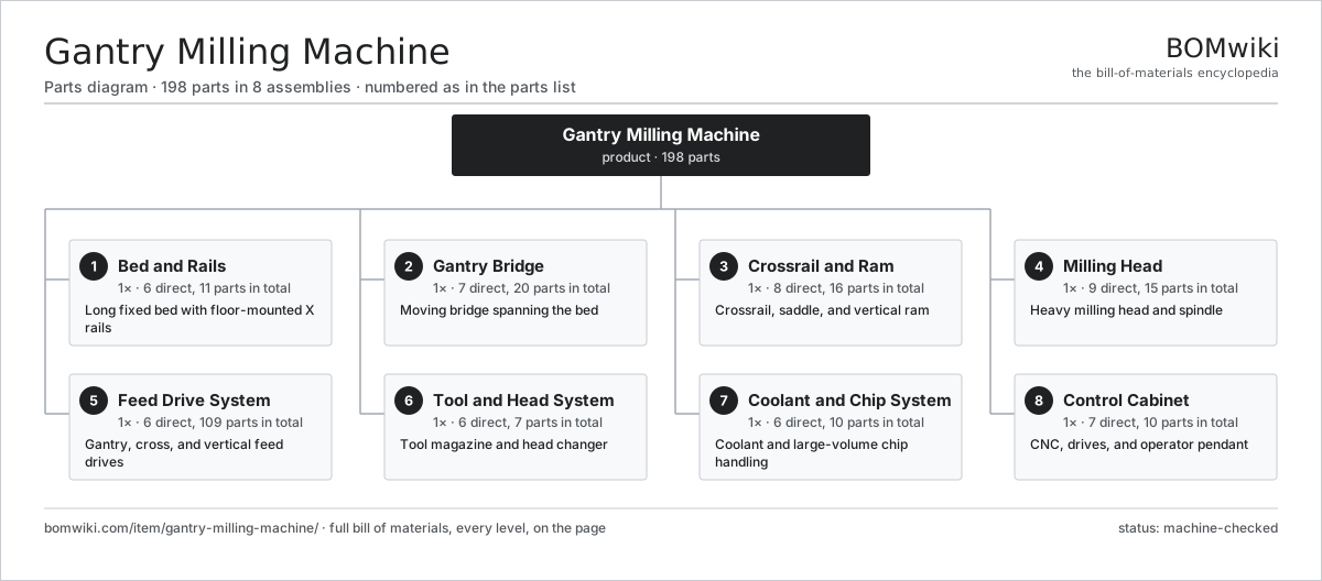
| # | Part | Qty | What it does |
|---|---|---|---|
| 1 | Bed and Rails 6 parts | 1× | Long fixed bed with floor-mounted X rails |
| 2 | Gantry Bridge 7 parts | 1× | Moving bridge spanning the bed |
| 3 | Crossrail and Ram 8 parts | 1× | Crossrail, saddle, and vertical ram |
| 4 | Milling Head 9 parts | 1× | Heavy milling head and spindle |
| 5 | Feed Drive System 6 parts | 1× | Gantry, cross, and vertical feed drives |
| 6 | Tool and Head System 6 parts | 1× | Tool magazine and head changer |
| 7 | Coolant and Chip System 6 parts | 1× | Coolant and large-volume chip handling |
| 8 | Control Cabinet 7 parts | 1× | CNC, drives, and operator pendant |
3D model
No 3D model yet. Have a CAD file of this? Add a 3D model — STL renders right on this page; STEP, FreeCAD, and OpenSCAD sources are welcome too (openly licensed, like all 3D models on BOMwiki).
Build & assembly graph
expand / collapse · shared sub-assemblies converge · links to related products · est. labourTap an assembly to expand/collapse · tap a part to open it · use “Open page” for any node · drag to pan, scroll to zoom.
Bill of materials for Gantry Milling Machine
8 top-level lines · 67 rows shown · 198 parts total · indented to 3 levels| # | Item / sub-assembly | Part no. | Qty/assy | Ext. qty | Parts | Type |
|---|---|---|---|---|---|---|
| 1 | Bed and Rails 6 parts | gmm-bed-rails | 1× | 1 | 11 | assembly |
| 1.1 | Bed Section | gmm-bed-section | 4× | 4 | · | part |
| 1.2 | X Rail | gmm-x-rail | 2× | 2 | · | part |
| 1.3 | T-Slot Table | gmm-t-slot-table | 1× | 1 | · | part |
| 1.4 | Drive Rack | gmm-rack | 2× | 2 | · | part |
| 1.5 | Foundation Anchor Set | gmm-anchor-set | 1× | 1 | · | part |
| 1.6 | Fastener Set | fastener-set | 1× | 1 | · | part |
| 2 | Gantry Bridge 7 parts | gmm-gantry-bridge | 1× | 1 | 20 | assembly |
| 2.1 | Bridge Upright | gmm-upright | 2× | 2 | · | part |
| 2.2 | Crossbeam | gmm-crossbeam | 1× | 1 | · | part |
| 2.3 | X Truck | gmm-x-truck | 4× | 4 | · | part |
| 2.4 | X Drive Pinion | gmm-x-pinion | 2× | 2 | · | part |
| 2.5 | Helical Gear Pair | gear-pair | 2× | 2 | · | part |
| 2.6 | Ball Bearing | ball-bearing | 8× | 8 | · | part |
| 2.7 | Fastener Set | fastener-set | 1× | 1 | · | part |
| 3 | Crossrail and Ram 8 parts | gmm-crossrail-ram | 1× | 1 | 16 | assembly |
| 3.1 | Crossrail | gmm-crossrail | 1× | 1 | · | part |
| 3.2 | Saddle | gmm-saddle | 1× | 1 | · | part |
| 3.3 | Ram | gmm-ram | 1× | 1 | · | part |
| 3.4 | Y Ball Screw | gmm-y-screw | 1× | 1 | · | part |
| 3.5 | Z Ball Screw | gmm-z-screw | 1× | 1 | · | part |
| 3.6 | Linear Guide Rail | linear-guide | 4× | 4 | · | part |
| 3.7 | Counterbalance Cylinder | gmm-counterbalance | 1× | 1 | · | part |
| 3.8 | Ball Bearing | ball-bearing | 6× | 6 | · | part |
| 4 | Milling Head 9 parts | gmm-milling-head | 1× | 1 | 15 | assembly |
| 4.1 | Head Body | gmm-head-body | 1× | 1 | · | part |
| 4.2 | Milling Spindle | gmm-spindle | 1× | 1 | · | part |
| 4.3 | Head Motor | gmm-head-motor | 1× | 1 | · | part |
| 4.4 | Gearbox Housing | gearbox-housing | 1× | 1 | · | part |
| 4.5 | Helical Gear Pair | gear-pair | 2× | 2 | · | part |
| 4.6 | Spindle Taper | gmm-spindle-taper | 1× | 1 | · | part |
| 4.7 | Power Drawbar | gmm-drawbar | 1× | 1 | · | part |
| 4.8 | Ball Bearing | ball-bearing | 5× | 5 | · | part |
| 4.9 | Oil Seal | oil-seal | 2× | 2 | · | part |
| 5 | Feed Drive System 6 parts | gmm-drive-system | 1× | 1 | 109 | assembly |
| 5.1 | Servo Motor 4 parts | servo-motor | 4× | 4 | 24 | assembly |
| 5.1.1 | Stator Assembly 3 parts + deeper › | stator-assembly | 1× | 4 | 3 | assembly |
| 5.1.2 | Rotor Assembly 4 parts + deeper › | rotor-assembly | 1× | 4 | 19 | assembly |
| 5.1.3 | Encoder | encoder | 1× | 4 | · | part |
| 5.1.4 | Motor Housing | motor-housing | 1× | 4 | · | part |
| 5.2 | X Linear Scale | gmm-x-scale | 2× | 2 | · | part |
| 5.3 | Y/Z Linear Scale | gmm-yz-scale | 2× | 2 | · | part |
| 5.4 | Drive Coupling | gmm-coupling | 4× | 4 | · | part |
| 5.5 | Lubrication System | gmm-lube-system | 1× | 1 | · | part |
| 5.6 | Ball Bearing | ball-bearing | 4× | 4 | · | part |
| 6 | Tool and Head System 6 parts | gmm-tool-system | 1× | 1 | 7 | assembly |
| 6.1 | Tool Magazine | gmm-tool-magazine | 1× | 1 | · | part |
| 6.2 | Tool Change Arm | gmm-changer-arm | 1× | 1 | · | part |
| 6.3 | Head Store | gmm-head-store | 1× | 1 | · | part |
| 6.4 | Head Coupler | gmm-head-coupler | 1× | 1 | · | part |
| 6.5 | Magazine Motor | gmm-magazine-motor | 1× | 1 | · | part |
| 6.6 | Relay | relay | 2× | 2 | · | part |
| 7 | Coolant and Chip System 6 parts | gmm-coolant-chip | 1× | 1 | 10 | assembly |
| 7.1 | Coolant Tank | gmm-coolant-tank | 1× | 1 | · | part |
| 7.2 | Coolant Pump | gmm-coolant-pump | 2× | 2 | · | part |
| 7.3 | Bed Chip Conveyor | gmm-bed-conveyor | 1× | 1 | · | part |
| 7.4 | Coolant Nozzle | gmm-coolant-nozzle | 4× | 4 | · | part |
| 7.5 | Coolant Filter | vmc-coolant-filter | 1× | 1 | · | part |
| 7.6 | O-Ring Set | oring-set | 1× | 1 | · | part |
| 8 | Control Cabinet 7 parts | gmm-control-cabinet | 1× | 1 | 10 | assembly |
| 8.1 | CNC Control | gmm-cnc-control | 1× | 1 | · | part |
| 8.2 | Servo Amplifier | gmm-servo-amp | 4× | 4 | · | part |
| 8.3 | Operator Pendant | gmm-pendant | 1× | 1 | · | part |
| 8.4 | Power Supply | power-supply | 1× | 1 | · | part |
| 8.5 | Machine PLC | gmm-plc | 1× | 1 | · | part |
| 8.6 | LCD Panel | lcd-panel | 1× | 1 | · | part |
| 8.7 | Wire Bundle | wire-bundle | 1× | 1 | · | part |
Related products
same domain, ranked by shared parts Bed-Type Milling Machine
151 parts · shares 6 with this page
Bed-Type Milling Machine
151 parts · shares 6 with this page
 Five-Axis Machining Center
168 parts · shares 6 with this page
Five-Axis Machining Center
168 parts · shares 6 with this page
 Horizontal Machining Center
240 parts · shares 6 with this page
Horizontal Machining Center
240 parts · shares 6 with this page
 Vertical Machining Center
195 parts · shares 6 with this page
Vertical Machining Center
195 parts · shares 6 with this page
 Bevel Gear Generator
201 parts · shares 6 with this page
Centering and Facing Machine
1,419 parts · shares 6 with this page
Bevel Gear Generator
201 parts · shares 6 with this page
Centering and Facing Machine
1,419 parts · shares 6 with this page
Sourcing: possible vendors
Prices, MOQ, and lead times are algorithmic estimates, not quotes, and not claims about these companies. Company mappings are curated by keyword; est. price band $10k–$1M. How estimates work| Vendor | HQ | Specialty | MOQ | Lead time |
|---|---|---|---|---|
|
🇩🇪DMG MORI
dmgmori.com ↗
|
Bielefeld, DE | Machine tools | 5 units | 12–20 wks |
|
🇯🇵Mazak
mazak.com ↗
|
Oguchi, JP | Machine tools | 5 units | 12–20 wks |
| haascnc.com ↗ | Oxnard, US | CNC machine tools | 5 units | 12–20 wks |
|
🇯🇵Okuma
okuma.com ↗
|
Niwa, JP | Machine tools | 5 units | 12–20 wks |
|
🇩🇪Trumpf
trumpf.com ↗
|
Ditzingen, DE | Laser & sheet-metal machines | 5 units | 12–20 wks |
952-word article