Surface Broaching Machine
ProductOverview
A surface broaching machine cuts a flat, a slot or a contoured surface in a single straight pass of a toothed tool. The broach is a long bar whose teeth each stand a few hundredths of a millimetre taller than the one before it, so as the bar is pulled across the work each tooth shaves off its own thin layer and the surface reaches full depth in one stroke. There is no feeding to depth and no repeated passes: the depth is built into the tool. That makes broaching one of the fastest and most repeatable ways to machine a surface, which is why it is used for high-volume parts such as engine block deck faces, connecting-rod splits, gear-rack teeth and turbine fir-tree slots.
The machine is built around a Bed & Frame stiff enough to react the cutting load without flexing. The Broach Ram carries the Broach Tooling and is dragged across the work by the Ram Drive, while the Work Fixture holds the part down against the cut. A Hydraulic Power Unit unit powers the stroke and the clamps, and the Machine Control sequences the cycle.
How it works
Cutting force in broaching is large and almost constant, because many teeth are in the cut at once. The Ram Drive is a big hydraulic cylinder fed through a Servo Valve that meters oil to hold a steady cutting speed even as the number of engaged teeth rises and falls. The Main Cylinder pulls the Ram Body along the Ram Way, and the Linear Scale reads ram position so the control knows exactly when the broach clears the part and can begin the fast return.
The teeth of the Broach Bar are arranged in sections: roughing teeth take the bulk of the metal, semi-finishing teeth refine the shape, and finishing teeth set the final size and finish in the last few teeth. Because every tooth cuts only once per stroke, tool life is long, but the whole geometry depends on the tooth height progression staying exact, which is why the bar is reground as a set and reset with the Height Shim stack.
Workholding
The cut pushes the part upward and sideways, so holding it firmly matters as much as the tool. The Work Fixture locates the part on hardened Locating Pad pads and clamps it to the Fixture Bolster with Hydraulic Clamp power clamps. The bolster sits directly under the cut so the part cannot deflect as the teeth pass. After the stroke a Pneumatic Cylinder ejector lifts the finished part for unloading. Fixtures are usually built for one part family, and changing them over is the main setup task when the machine moves to a new job.
Hydraulics
The Hydraulic Power Unit is the largest subsystem. A variable-displacement Main Pump supplies oil at high pressure to the ram cylinder and the clamps. A Accumulator smooths the pressure as the load changes through the stroke, and a Oil Cooler holds the oil temperature steady so its viscosity, and therefore the cutting speed, stays constant from the first part of a shift to the last. Pressure at the cylinder is watched by a Pressure Sensor so the control can confirm full clamping before the stroke begins and detect an overload during the cut.
Coolant and chips
Broaching makes long, curled chips that have to clear the gullets between teeth or they jam and break the tool. The Coolant System system floods the broach with cutting oil through aimed Flood Nozzle jets, washing chips out of the gullets and cooling the teeth. The Coolant Pump keeps the flow high, and the returning oil settles its chips in the Coolant Tank before being pumped again. Good chip flushing is what lets the machine run thousands of strokes between regrinds.
Control, safety and use
The Machine Control runs the whole cycle from a PLC: clamp the part, pull the broach at cutting speed, dwell, return fast, release and eject. The operator sets stroke length and speed at the HMI Panel. Because the ram moves with great force, the Guarding encloses the work zone and a Light Curtain stops the stroke if anything breaks the beam. Surface broaches handle automotive blocks and heads, connecting rods, gear racks, dovetails, and the fir-tree root slots on turbine blades and discs. Variants include vertical pull-down machines that save floor space and continuous chain machines that broach a stream of parts without stopping between strokes.
Surface Broaching Machine parts and their functions
10 top-level parts · 219 parts in total · full bill of materials below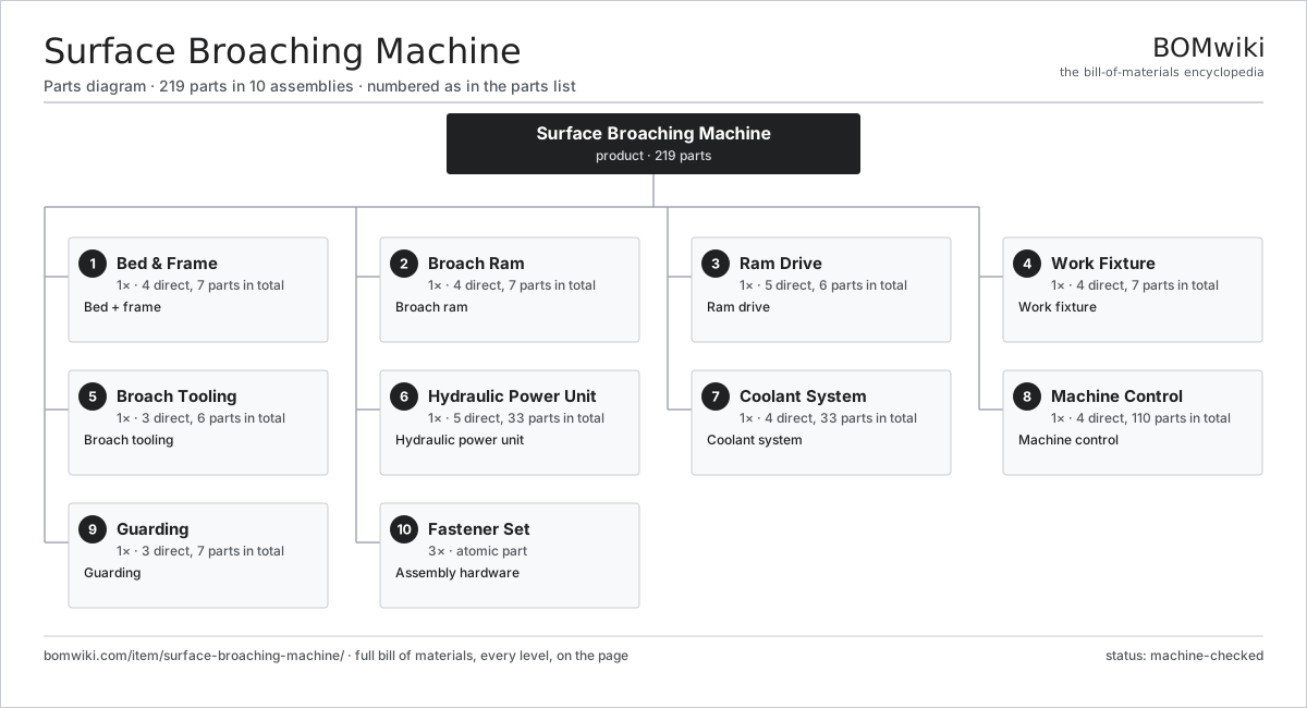
| # | Part | Qty | What it does |
|---|---|---|---|
| 1 | Bed & Frame 4 parts | 1× | Bed + frame |
| 2 | Broach Ram 4 parts | 1× | Broach ram |
| 3 | Ram Drive 5 parts | 1× | Ram drive |
| 4 | Work Fixture 4 parts | 1× | Work fixture |
| 5 | Broach Tooling 3 parts | 1× | Broach tooling |
| 6 | Hydraulic Power Unit 5 parts | 1× | Hydraulic power unit |
| 7 | Coolant System 4 parts | 1× | Coolant system |
| 8 | Machine Control 4 parts | 1× | Machine control |
| 9 | Guarding 3 parts | 1× | Guarding |
| 10 | Fastener Set | 3× | Assembly hardware |
3D model
No 3D model yet. Have a CAD file of this? Add a 3D model — STL renders right on this page; STEP, FreeCAD, and OpenSCAD sources are welcome too (openly licensed, like all 3D models on BOMwiki).
Build & assembly graph
expand / collapse · shared sub-assemblies converge · links to related products · est. labourTap an assembly to expand/collapse · tap a part to open it · use “Open page” for any node · drag to pan, scroll to zoom.
Bill of materials for Surface Broaching Machine
10 top-level lines · 60 rows shown · 219 parts total · indented to 3 levels| # | Item / sub-assembly | Part no. | Qty/assy | Ext. qty | Parts | Type |
|---|---|---|---|---|---|---|
| 1 | Bed & Frame 4 parts | surface-broaching-machine-bed | 1× | 1 | 7 | assembly |
| 1.1 | Welded Frame | surface-broaching-machine-frame | 1× | 1 | · | part |
| 1.2 | Ram Way | surface-broaching-machine-way | 2× | 2 | · | part |
| 1.3 | Tie Bar | surface-broaching-machine-tie-bar | 2× | 2 | · | part |
| 1.4 | Fastener Set | fastener-set | 2× | 2 | · | part |
| 2 | Broach Ram 4 parts | surface-broaching-machine-ram | 1× | 1 | 7 | assembly |
| 2.1 | Ram Body | surface-broaching-machine-ram-body | 1× | 1 | · | part |
| 2.2 | Broach Puller Head | surface-broaching-machine-puller | 1× | 1 | · | part |
| 2.3 | Adjustable Gib | surface-broaching-machine-gib | 4× | 4 | · | part |
| 2.4 | Linear Scale | surface-broaching-machine-scale | 1× | 1 | · | part |
| 3 | Ram Drive 5 parts | surface-broaching-machine-drive | 1× | 1 | 6 | assembly |
| 3.1 | Main Cylinder | surface-broaching-machine-cylinder | 1× | 1 | · | part |
| 3.2 | Piston Rod | piston-rod | 1× | 1 | · | part |
| 3.3 | Servo Valve | surface-broaching-machine-servo-valve | 1× | 1 | · | part |
| 3.4 | Pressure Sensor | pressure-sensor | 2× | 2 | · | part |
| 3.5 | O-Ring Set | oring-set | 1× | 1 | · | part |
| 4 | Work Fixture 4 parts | surface-broaching-machine-fixture | 1× | 1 | 7 | assembly |
| 4.1 | Fixture Bolster | surface-broaching-machine-bolster | 1× | 1 | · | part |
| 4.2 | Hydraulic Clamp | surface-broaching-machine-clamp | 2× | 2 | · | part |
| 4.3 | Locating Pad | surface-broaching-machine-locator | 3× | 3 | · | part |
| 4.4 | Pneumatic Cylinder | pneumatic-cylinder | 1× | 1 | · | part |
| 5 | Broach Tooling 3 parts | surface-broaching-machine-broach | 1× | 1 | 6 | assembly |
| 5.1 | Broach Bar | surface-broaching-machine-broach-bar | 1× | 1 | · | part |
| 5.2 | Height Shim | surface-broaching-machine-shim | 4× | 4 | · | part |
| 5.3 | Broach Holder | surface-broaching-machine-holder | 1× | 1 | · | part |
| 6 | Hydraulic Power Unit 5 parts | surface-broaching-machine-hydraulics | 1× | 1 | 33 | assembly |
| 6.1 | Main Pump 5 parts | surface-broaching-machine-hyd-pump | 1× | 1 | 26 | assembly |
| 6.1.1 | Stator Assembly 3 parts + deeper › | stator-assembly | 1× | 1 | 3 | assembly |
| 6.1.2 | Rotor Assembly 4 parts + deeper › | rotor-assembly | 1× | 1 | 19 | assembly |
| 6.1.3 | Motor Housing | motor-housing | 1× | 1 | · | part |
| 6.1.4 | Ball Bearing | ball-bearing | 2× | 2 | · | part |
| 6.1.5 | Oil Seal | oil-seal | 1× | 1 | · | part |
| 6.2 | Oil Tank | surface-broaching-machine-tank | 1× | 1 | · | part |
| 6.3 | Accumulator | surface-broaching-machine-accumulator | 1× | 1 | · | part |
| 6.4 | Oil Cooler | surface-broaching-machine-cooler | 1× | 1 | · | part |
| 6.5 | Relay | relay | 4× | 4 | · | part |
| 7 | Coolant System 4 parts | surface-broaching-machine-coolant | 1× | 1 | 33 | assembly |
| 7.1 | Coolant Pump 5 parts | surface-broaching-machine-coolant-pump | 1× | 1 | 26 | assembly |
| 7.1.1 | Stator Assembly 3 parts + deeper › | stator-assembly | 1× | 1 | 3 | assembly |
| 7.1.2 | Rotor Assembly 4 parts + deeper › | rotor-assembly | 1× | 1 | 19 | assembly |
| 7.1.3 | Motor Housing | motor-housing | 1× | 1 | · | part |
| 7.1.4 | Ball Bearing | ball-bearing | 2× | 2 | · | part |
| 7.1.5 | Oil Seal | oil-seal | 1× | 1 | · | part |
| 7.2 | Coolant Tank | coolant-tank | 1× | 1 | · | part |
| 7.3 | Flood Nozzle | surface-broaching-machine-nozzle | 3× | 3 | · | part |
| 7.4 | Coolant Hose | coolant-hose | 3× | 3 | · | part |
| 8 | Machine Control 4 parts | surface-broaching-machine-control | 1× | 1 | 110 | assembly |
| 8.1 | PLC 4 parts | surface-broaching-machine-plc | 1× | 1 | 98 | assembly |
| 8.1.1 | Bare PCB | pcb-bare | 1× | 1 | · | part |
| 8.1.2 | Microcontroller | mcu | 1× | 1 | · | part |
| 8.1.3 | Relay | relay | 6× | 6 | · | part |
| 8.1.4 | SMD Passive (R/C/L) | smd-passives | 90× | 90 | · | part |
| 8.2 | HMI Panel | hmi-panel | 1× | 1 | · | part |
| 8.3 | Wire Bundle | wire-bundle | 1× | 1 | · | part |
| 8.4 | Connector | connector | 10× | 10 | · | part |
| 9 | Guarding 3 parts | surface-broaching-machine-guard | 1× | 1 | 7 | assembly |
| 9.1 | Sheet Metal Panel | sheet-panel | 4× | 4 | · | part |
| 9.2 | Light Curtain | surface-broaching-machine-light-curtain | 1× | 1 | · | part |
| 9.3 | Limit Switch | limit-switch | 2× | 2 | · | part |
| 10 | Fastener Set | fastener-set | 3× | 3 | · | part |
Related products
same domain, ranked by shared parts CNC Milling Machine
400 parts · shares 6 with this page
Gear Shaving Machine
240 parts · shares 4 with this page
CNC Milling Machine
400 parts · shares 6 with this page
Gear Shaving Machine
240 parts · shares 4 with this page
 Vertical Boring Mill
265 parts · shares 4 with this page
Vertical Boring Mill
265 parts · shares 4 with this page
 CNC Lathe
511 parts · shares 5 with this page
CNC Lathe
511 parts · shares 5 with this page
Sourcing: possible vendors
Prices, MOQ, and lead times are algorithmic estimates, not quotes, and not claims about these companies. Company mappings are curated by keyword; est. price band $10k–$1M. How estimates work| Vendor | HQ | Specialty | MOQ | Lead time |
|---|---|---|---|---|
|
🇩🇪DMG MORI
dmgmori.com ↗
|
Bielefeld, DE | Machine tools | 5 units | 12–20 wks |
|
🇯🇵Mazak
mazak.com ↗
|
Oguchi, JP | Machine tools | 5 units | 12–20 wks |
| haascnc.com ↗ | Oxnard, US | CNC machine tools | 5 units | 12–20 wks |
|
🇯🇵Okuma
okuma.com ↗
|
Niwa, JP | Machine tools | 5 units | 12–20 wks |
|
🇩🇪Trumpf
trumpf.com ↗
|
Ditzingen, DE | Laser & sheet-metal machines | 5 units | 12–20 wks |
814-word article