Spline Rolling Machine
ProductOverview
A spline rolling machine forms splines, serrations, and similar tooth profiles on shafts without cutting any metal away. The blank turns between two driven toothed dies that are pressed into its surface; where a die tooth pushes in, the displaced material flows up to form the spline tooth alongside. Because nothing is cut, the process is called chipless or cold forming. It competes with hobbing, shaping, and broaching for medium and high volume parts such as gearbox shafts, axle shafts, steering columns, pump shafts, and starter pinion shafts. The two common machine layouts are the two-cylindrical-die type, where each Rolling Die is a hardened round gear-form roll, and the flat-die reciprocating type, where two toothed racks move past the work in opposite directions. The cylindrical-die machine described here covers the larger share of production splining.
How it works
The work is located between two 60-degree Live Center points carried by the Headstock and Tailstock, or held in a Work Chuck when there are no center holes. The Synchronizing Drive turns both dies at the same surface speed and in locked phase through a 1:1 geartrain, so the teeth of both dies always enter the same spline space. Before production runs, the Die Phasing Adjuster is set so the two dies engage matching tooth spaces on opposite sides of the blank; if they are out of phase the part comes out double-tracked or with mismatched teeth.
With the dies turning, the Infeed System closes the two die spindles symmetrically toward the work centerline. Each Infeed Cylinder supplies the radial force, commonly between 10 and 100 t depending on tooth module, spline length, and material. The dies do not reach full depth on the first revolution. Penetration builds over several revolutions of the part, so the metal flows gradually into the die form rather than being forced in one bite. The Depth Stop limits final penetration, fixing the major diameter and tooth depth, and a Rolling Load Cell in the slide path lets the control watch rolling tonnage and reject a blank that is too hard or oversized. After a short dwell at full depth to round out the form, the slides retract and the finished shaft is ejected.
Why cold rolling is used
Rolling moves metal instead of removing it, and that has direct mechanical consequences. The grain flow of the bar follows the tooth contour rather than being cut through, so the spline roots, where fatigue cracks usually start, carry uninterrupted fibers. The cold work raises surface hardness and leaves compressive residual stress in the flanks. The result is a spline with higher torsional and bending fatigue strength than a cut spline of the same geometry, which is why drivetrain and steering shafts favor the process. Rolling also produces no chips, uses the full bar cross section, and runs fast: a typical cycle is a few seconds to roll a complete spline, against the minutes a hob or shaper would take. The trade is that the blank diameter must be controlled closely, since the rolled major diameter and tooth thickness depend on how much material is available to flow, and very deep or very coarse splines exceed the force the process can apply.
Dies and tooling
The dies are the heart of the machine. Each Rolling Die carries the negative of the spline form and is made from M2 or D2 tool steel hardened to roughly 60-62 HRC, then ground and sometimes coated to resist the repeated high-contact-stress rolling. A die set is matched and lasts for many thousands of parts before the tooth flanks wear enough to drift the spline out of tolerance. Dies mount on a keyed Die Arbor so a worn set can be swapped and re-indexed without losing the phase relationship. The Die Head Housing holds both Die Spindle units parallel and reacts the spreading force; any flex here prints as spacing or lead error on the spline. Flat-die machines instead use two toothed racks, one fixed or both reciprocating, that roll the work between them in a single linear pass, a layout suited to short splines and serrations at very high rates.
Hydraulics and drive
The Hydraulic Power Unit generates the rolling force. A variable-displacement Hydraulic Pump supplies oil at 210-250 bar through the Valve Manifold, which sequences infeed, dwell, retract, and tailstock motions. An Accumulator absorbs the pressure spike as the dies reach full penetration and steadies the holding force during dwell. Because the process puts heat into both the oil and the dies, an Oil Cooler keeps hydraulic viscosity stable and the Lubrication and Coolant system floods the die-work contact to cut friction, flush metal fines, and carry off the heat of plastic deformation. The Main Drive Motor, typically 15 to 75 kW, drives both loaded dies through the synchronizing gearbox; rolling torque peaks as the teeth approach full depth.
Control and structure
A CNC/PLC Control sequences the cycle, compares rolling force against per-part limits, and counts production, while CNC versions store a penetration profile per part number and adjust feed for different materials. The operator works through the Operator HMI for phasing setup, force trends, and recipes. Holding all of this in alignment is the Bed and Frame: a heavy cast or fabricated Machine Bed closed by pre-tensioned Frame Tie Rods so the structure does not stretch when the dies press apart under full tonnage. Long or slender shafts get a Steady Rest mid-span to limit the bending deflection that the opposed radial die forces would otherwise cause. High-volume cells add a Loader Interface so blanks are fed between centers and finished shafts removed without an operator at the throat.
Spline Rolling Machine parts and their functions
8 top-level parts · 138 parts in total · full bill of materials below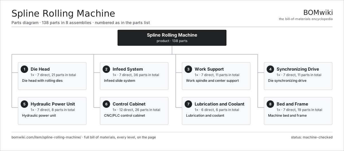
| # | Part | Qty | What it does |
|---|---|---|---|
| 1 | Die Head 7 parts | 1× | Die head with rolling dies |
| 2 | Infeed System 7 parts | 1× | Infeed slide system |
| 3 | Work Support 7 parts | 1× | Work spindle and center support |
| 4 | Synchronizing Drive 7 parts | 1× | Die synchronizing drive |
| 5 | Hydraulic Power Unit 7 parts | 1× | Hydraulic power unit |
| 6 | Control Cabinet 12 parts | 1× | CNC/PLC control cabinet |
| 7 | Lubrication and Coolant 6 parts | 1× | Lubrication and coolant |
| 8 | Bed and Frame 7 parts | 1× | Machine bed and frame |
3D model
No 3D model yet. Have a CAD file of this? Add a 3D model — STL renders right on this page; STEP, FreeCAD, and OpenSCAD sources are welcome too (openly licensed, like all 3D models on BOMwiki).
Build & assembly graph
expand / collapse · shared sub-assemblies converge · links to related products · est. labourTap an assembly to expand/collapse · tap a part to open it · use “Open page” for any node · drag to pan, scroll to zoom.
Bill of materials for Spline Rolling Machine
8 top-level lines · 72 rows shown · 138 parts total · indented to 3 levels| # | Item / sub-assembly | Part no. | Qty/assy | Ext. qty | Parts | Type |
|---|---|---|---|---|---|---|
| 1 | Die Head 7 parts | spline-rolling-machine-die-head | 1× | 1 | 21 | assembly |
| 1.1 | Rolling Die | spline-rolling-machine-rolling-die | 2× | 2 | · | part |
| 1.2 | Die Spindle | spline-rolling-machine-die-spindle | 2× | 2 | · | part |
| 1.3 | Die Arbor | spline-rolling-machine-die-arbor | 2× | 2 | · | part |
| 1.4 | Die Head Housing | spline-rolling-machine-die-housing | 1× | 1 | · | part |
| 1.5 | Die Phasing Adjuster | spline-rolling-machine-phase-adjust | 2× | 2 | · | part |
| 1.6 | Ball Bearing | ball-bearing | 8× | 8 | · | part |
| 1.7 | Oil Seal | oil-seal | 4× | 4 | · | part |
| 2 | Infeed System 7 parts | spline-rolling-machine-infeed-system | 1× | 1 | 36 | assembly |
| 2.1 | Infeed Slide | spline-rolling-machine-infeed-slide | 2× | 2 | · | part |
| 2.2 | Infeed Cylinder | spline-rolling-machine-infeed-cylinder | 2× | 2 | · | part |
| 2.3 | Slide Ways | spline-rolling-machine-slide-ways | 2× | 2 | · | part |
| 2.4 | Depth Stop | spline-rolling-machine-depth-stop | 2× | 2 | · | part |
| 2.5 | Rolling Load Cell | spline-rolling-machine-load-cell | 2× | 2 | · | part |
| 2.6 | Linear Guide Rail | linear-guide | 2× | 2 | · | part |
| 2.7 | Servo Motor 4 parts | servo-motor | 1× | 1 | 24 | assembly |
| 2.7.1 | Stator Assembly 3 parts + deeper › | stator-assembly | 1× | 1 | 3 | assembly |
| 2.7.2 | Rotor Assembly 4 parts + deeper › | rotor-assembly | 1× | 1 | 19 | assembly |
| 2.7.3 | Encoder | encoder | 1× | 1 | · | part |
| 2.7.4 | Motor Housing | motor-housing | 1× | 1 | · | part |
| 3 | Work Support 7 parts | spline-rolling-machine-work-support | 1× | 1 | 11 | assembly |
| 3.1 | Headstock | spline-rolling-machine-headstock | 1× | 1 | · | part |
| 3.2 | Tailstock | spline-rolling-machine-tailstock | 1× | 1 | · | part |
| 3.3 | Live Center | spline-rolling-machine-live-center | 2× | 2 | · | part |
| 3.4 | Steady Rest | spline-rolling-machine-steady-rest | 1× | 1 | · | part |
| 3.5 | Work Chuck | spline-rolling-machine-chuck | 1× | 1 | · | part |
| 3.6 | Loader Interface | spline-rolling-machine-loader | 1× | 1 | · | part |
| 3.7 | Ball Bearing | ball-bearing | 4× | 4 | · | part |
| 4 | Synchronizing Drive 7 parts | spline-rolling-machine-sync-drive | 1× | 1 | 11 | assembly |
| 4.1 | Main Drive Motor | spline-rolling-machine-main-motor | 1× | 1 | · | part |
| 4.2 | Synchronizing Gearbox | spline-rolling-machine-sync-gearbox | 1× | 1 | · | part |
| 4.3 | Helical Gear Pair | gear-pair | 2× | 2 | · | part |
| 4.4 | Gearbox Housing | gearbox-housing | 1× | 1 | · | part |
| 4.5 | Drive Belt | drive-belt | 1× | 1 | · | part |
| 4.6 | Encoder | encoder | 2× | 2 | · | part |
| 4.7 | Oil Seal | oil-seal | 3× | 3 | · | part |
| 5 | Hydraulic Power Unit 7 parts | spline-rolling-machine-hpu | 1× | 1 | 8 | assembly |
| 5.1 | Hydraulic Pump | spline-rolling-machine-hyd-pump | 1× | 1 | · | part |
| 5.2 | Oil Reservoir | spline-rolling-machine-hyd-tank | 1× | 1 | · | part |
| 5.3 | Valve Manifold | spline-rolling-machine-hyd-manifold | 1× | 1 | · | part |
| 5.4 | Accumulator | spline-rolling-machine-accumulator | 1× | 1 | · | part |
| 5.5 | Oil Cooler | spline-rolling-machine-hyd-cooler | 1× | 1 | · | part |
| 5.6 | Pressure Sensor | pressure-sensor | 2× | 2 | · | part |
| 5.7 | O-Ring Set | oring-set | 1× | 1 | · | part |
| 6 | Control Cabinet 12 parts | spline-rolling-machine-controls | 1× | 1 | 26 | assembly |
| 6.1 | CNC/PLC Control | spline-rolling-machine-plc | 1× | 1 | · | part |
| 6.2 | Operator HMI | spline-rolling-machine-hmi | 1× | 1 | · | part |
| 6.3 | Drive Module | spline-rolling-machine-drive-module | 2× | 2 | · | part |
| 6.4 | Power Supply | power-supply | 1× | 1 | · | part |
| 6.5 | IGBT Power Module | igbt-module | 2× | 2 | · | part |
| 6.6 | Relay | relay | 6× | 6 | · | part |
| 6.7 | Bare PCB | pcb-bare | 1× | 1 | · | part |
| 6.8 | Microcontroller | mcu | 1× | 1 | · | part |
| 6.9 | SMD Passive (R/C/L) | smd-passives | 1× | 1 | · | part |
| 6.10 | Connector | connector | 8× | 8 | · | part |
| 6.11 | Wire Bundle | wire-bundle | 1× | 1 | · | part |
| 6.12 | LCD Panel | lcd-panel | 1× | 1 | · | part |
| 7 | Lubrication and Coolant 6 parts | spline-rolling-machine-lube-coolant | 1× | 1 | 6 | assembly |
| 7.1 | Coolant Pump | coolant-pump | 1× | 1 | · | part |
| 7.2 | Lubricant Tank | spline-rolling-machine-lube-tank | 1× | 1 | · | part |
| 7.3 | Lubricant Filter | spline-rolling-machine-lube-filter | 1× | 1 | · | part |
| 7.4 | Lubricant Nozzles | spline-rolling-machine-lube-nozzles | 1× | 1 | · | part |
| 7.5 | Way Lubricator | spline-rolling-machine-way-lube | 1× | 1 | · | part |
| 7.6 | Pressure Sensor | pressure-sensor | 1× | 1 | · | part |
| 8 | Bed and Frame 7 parts | spline-rolling-machine-frame | 1× | 1 | 19 | assembly |
| 8.1 | Machine Bed | spline-rolling-machine-bed | 1× | 1 | · | part |
| 8.2 | Frame Tie Rods | spline-rolling-machine-tie-rods | 4× | 4 | · | part |
| 8.3 | Leveling Mount | spline-rolling-machine-leveling | 6× | 6 | · | part |
| 8.4 | Machine Enclosure | spline-rolling-machine-enclosure | 1× | 1 | · | part |
| 8.5 | Sheet Metal Panel | sheet-panel | 4× | 4 | · | part |
| 8.6 | Coil Spring | coil-spring | 2× | 2 | · | part |
| 8.7 | Fastener Set | fastener-set | 1× | 1 | · | part |
Related products
same domain, ranked by shared parts Rotary-Table Surface Grinder
172 parts · shares 11 with this page
Rotary-Table Surface Grinder
172 parts · shares 11 with this page
 Bevel Gear Generator
201 parts · shares 10 with this page
Bevel Gear Generator
201 parts · shares 10 with this page
 Radial Forging Machine
288 parts · shares 10 with this page
Double-Disc Grinder
153 parts · shares 9 with this page
Universal Cylindrical Grinder
153 parts · shares 8 with this page
Radial Forging Machine
288 parts · shares 10 with this page
Double-Disc Grinder
153 parts · shares 9 with this page
Universal Cylindrical Grinder
153 parts · shares 8 with this page
 Gear Shaping Machine
110 parts · shares 7 with this page
Gear Shaping Machine
110 parts · shares 7 with this page
Sourcing: possible vendors
Prices, MOQ, and lead times are algorithmic estimates, not quotes, and not claims about these companies. Company mappings are curated by keyword; est. price band $10k–$1M. How estimates work| Vendor | HQ | Specialty | MOQ | Lead time |
|---|---|---|---|---|
|
🇩🇪DMG MORI
dmgmori.com ↗
|
Bielefeld, DE | Machine tools | 5 units | 12–20 wks |
|
🇯🇵Mazak
mazak.com ↗
|
Oguchi, JP | Machine tools | 5 units | 12–20 wks |
| haascnc.com ↗ | Oxnard, US | CNC machine tools | 5 units | 12–20 wks |
|
🇯🇵Okuma
okuma.com ↗
|
Niwa, JP | Machine tools | 5 units | 12–20 wks |
|
🇩🇪Trumpf
trumpf.com ↗
|
Ditzingen, DE | Laser & sheet-metal machines | 5 units | 12–20 wks |
1,031-word article