Vertical Boring Mill
ProductOverview
A vertical boring mill, often called a vertical turret lathe, turns large and heavy parts that would be awkward or unsafe to swing on a horizontal lathe. The part sits flat on a rotating horizontal table and is gripped by power jaws on the table centre line. Tools mounted on a fixed structure above and beside the part feed into the rotating work to bore holes, face flat surfaces and turn outer diameters. Putting the spin axis vertical means gravity helps hold the part down and centred, so the machine handles flywheels, gear blanks, valve bodies, turbine casings and bearing rings up to two metres across.
The machine is built around the Base & Rotary Table, whose rotary table floats on a Hydrostatic Table Bearing so that several tonnes of part turn with low friction and high stiffness. The Column Structure rises from the base and carries the Cross Rail, a horizontal beam that can be raised to suit the part height. Riding the cross rail is the Vertical Ram Head, the main tool slide, and a separate Side Turret Head hangs off the column to work the outside of the part at the same time.
Table and drive
The heart of the machine is the table. The Rotary Table is a heavy faceplate, and the Self-Centring Jaws clamp the part to its centre. Because the table carries the full weight of the work and the radial cutting load, it runs on the hydrostatic bearing rather than rolling elements: pressurised oil from the Hydraulic System forms a film that the table glides on, which gives near-zero friction at start-up and damps chatter. The Table Drive turns the table through a two-step reduction so the Table Spindle Motor can deliver high torque at low speed for big-diameter cuts. As a tool feeds outward, the control raises the table speed to hold a constant surface speed at the cutting edge, which keeps the finish even from rim to centre.
Tool heads
The Vertical Ram Head does most of the cutting. Its Vertical Ram is a stiff square box that extends down from the Ram Saddle on the cross rail, and on its end an indexing Indexing Tool Turret carries up to five tools. The Ram Feed Servo feeds the ram down into the part to bore or face, while the saddle traverses the cross rail to set the cutting radius. The Side Turret Head adds a second cutting station: its Side Cross Slide rides the column ways and feeds tools radially to turn the outer diameter. Running both heads together cuts the inside and the outside of a ring in one chucking, which keeps the two surfaces concentric and roughly halves the cycle time.
Structure and rigidity
Heavy turning generates large, often interrupted cutting forces, so the frame is massive. The Base Casting and Column Casting are ribbed grey-iron castings chosen for their damping, and the larger mills close the frame into a bridge with a second column for extra stiffness. Every sliding joint runs on hardened, ground guideways: the Column Way guides the cross rail vertically and the Linear Guide Rail elements carry the saddle and the slides. Feed motion comes from preloaded Ball Screw drives backed by Position Encoder feedback, so the control knows true slide position rather than commanded position.
Hydraulics and coolant
The Hydraulic System does more than feed the table bearing. The same Hydraulic Pump clamps the power jaws, counterbalances the weight of the ram so the feed servo only has to control motion, and operates the cross-rail clamps. Pressure at each circuit is watched by a Pressure Sensor so the control can confirm the part is gripped before the table turns. The Coolant System floods the cut to clear heat and chips; because big steel cuts make heavy swarf, a Chip Conveyor drags the chips out of the coolant pan into a bin instead of relying on the coolant flow alone.
Control and use
The CNC Control runs the table and both heads as coordinated axes, often as two independent channels so each tool head can run its own cycle. The operator programs the part at the Operator Display, entering diameters, depths, feeds and the tool list; the control then sequences roughing and finishing passes and manages the turret indexing. Typical work is large bearing rings, gear and pulley blanks, brake rotors for rail and mining stock, pump and valve bodies, and wind-turbine and machine-tool castings. Variants range from single-column open-side machines for medium parts to double-column bridge machines and twin-table mills that load one part while the other is cut.
Vertical Boring Mill parts and their functions
10 top-level parts · 265 parts in total · full bill of materials below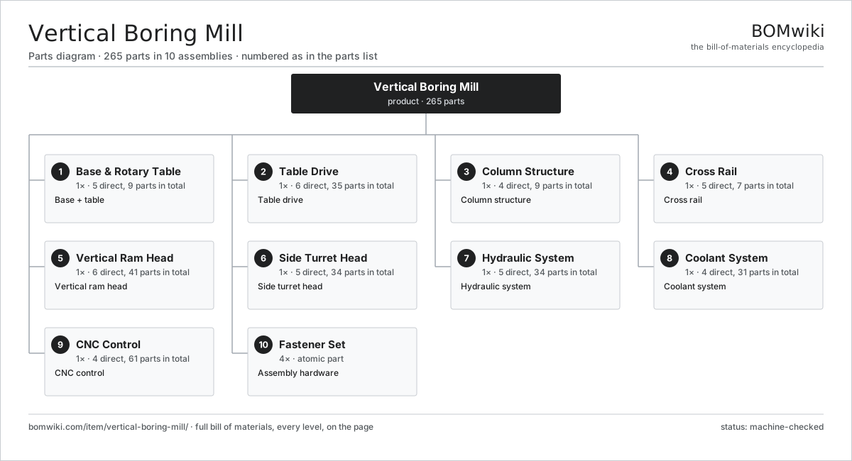
| # | Part | Qty | What it does |
|---|---|---|---|
| 1 | Base & Rotary Table 5 parts | 1× | Base + table |
| 2 | Table Drive 6 parts | 1× | Table drive |
| 3 | Column Structure 4 parts | 1× | Column structure |
| 4 | Cross Rail 5 parts | 1× | Cross rail |
| 5 | Vertical Ram Head 6 parts | 1× | Vertical ram head |
| 6 | Side Turret Head 5 parts | 1× | Side turret head |
| 7 | Hydraulic System 5 parts | 1× | Hydraulic system |
| 8 | Coolant System 4 parts | 1× | Coolant system |
| 9 | CNC Control 4 parts | 1× | CNC control |
| 10 | Fastener Set | 4× | Assembly hardware |
3D model
No 3D model yet. Have a CAD file of this? Add a 3D model — STL renders right on this page; STEP, FreeCAD, and OpenSCAD sources are welcome too (openly licensed, like all 3D models on BOMwiki).
Build & assembly graph
expand / collapse · shared sub-assemblies converge · links to related products · est. labourTap an assembly to expand/collapse · tap a part to open it · use “Open page” for any node · drag to pan, scroll to zoom.
Bill of materials for Vertical Boring Mill
10 top-level lines · 91 rows shown · 265 parts total · indented to 3 levels| # | Item / sub-assembly | Part no. | Qty/assy | Ext. qty | Parts | Type |
|---|---|---|---|---|---|---|
| 1 | Base & Rotary Table 5 parts | vertical-boring-mill-base | 1× | 1 | 9 | assembly |
| 1.1 | Base Casting | vertical-boring-mill-base-casting | 1× | 1 | · | part |
| 1.2 | Rotary Table | vertical-boring-mill-table | 1× | 1 | · | part |
| 1.3 | Hydrostatic Table Bearing | vertical-boring-mill-table-bearing | 1× | 1 | · | part |
| 1.4 | Self-Centring Jaws | vertical-boring-mill-jaws | 4× | 4 | · | part |
| 1.5 | Fastener Set | fastener-set | 2× | 2 | · | part |
| 2 | Table Drive 6 parts | vertical-boring-mill-table-drive | 1× | 1 | 35 | assembly |
| 2.1 | Table Spindle Motor 4 parts | vertical-boring-mill-table-motor | 1× | 1 | 25 | assembly |
| 2.1.1 | Stator Assembly 3 parts + deeper › | stator-assembly | 1× | 1 | 3 | assembly |
| 2.1.2 | Rotor Assembly 4 parts + deeper › | rotor-assembly | 1× | 1 | 19 | assembly |
| 2.1.3 | Motor Housing | motor-housing | 1× | 1 | · | part |
| 2.1.4 | Ball Bearing | ball-bearing | 2× | 2 | · | part |
| 2.2 | Gearbox Housing | gearbox-housing | 1× | 1 | · | part |
| 2.3 | Helical Gear Pair | gear-pair | 2× | 2 | · | part |
| 2.4 | Ball Bearing | ball-bearing | 4× | 4 | · | part |
| 2.5 | Oil Seal | oil-seal | 2× | 2 | · | part |
| 2.6 | Position Encoder | vertical-boring-mill-encoder | 1× | 1 | · | part |
| 3 | Column Structure 4 parts | vertical-boring-mill-column | 1× | 1 | 9 | assembly |
| 3.1 | Column Casting | vertical-boring-mill-column-casting | 1× | 1 | · | part |
| 3.2 | Column Way | vertical-boring-mill-column-way | 4× | 4 | · | part |
| 3.3 | Cross-Rail Lift Screw | vertical-boring-mill-crossrail-screw | 2× | 2 | · | part |
| 3.4 | Fastener Set | fastener-set | 2× | 2 | · | part |
| 4 | Cross Rail 5 parts | vertical-boring-mill-crossrail | 1× | 1 | 7 | assembly |
| 4.1 | Cross-Rail Casting | vertical-boring-mill-crossrail-casting | 1× | 1 | · | part |
| 4.2 | Ram Saddle | vertical-boring-mill-saddle | 1× | 1 | · | part |
| 4.3 | Linear Guide Rail | linear-guide | 2× | 2 | · | part |
| 4.4 | Ball Screw | ball-screw | 1× | 1 | · | part |
| 4.5 | Ball Bearing | ball-bearing | 2× | 2 | · | part |
| 5 | Vertical Ram Head 6 parts | vertical-boring-mill-ram-head | 1× | 1 | 41 | assembly |
| 5.1 | Vertical Ram | vertical-boring-mill-ram | 1× | 1 | · | part |
| 5.2 | Ram Feed Servo 5 parts | vertical-boring-mill-ram-servo | 1× | 1 | 26 | assembly |
| 5.2.1 | Stator Assembly 3 parts + deeper › | stator-assembly | 1× | 1 | 3 | assembly |
| 5.2.2 | Rotor Assembly 4 parts + deeper › | rotor-assembly | 1× | 1 | 19 | assembly |
| 5.2.3 | Motor Housing | motor-housing | 1× | 1 | · | part |
| 5.2.4 | Ball Bearing | ball-bearing | 2× | 2 | · | part |
| 5.2.5 | Position Encoder | vertical-boring-mill-encoder | 1× | 1 | · | part |
| 5.3 | Ball Screw | ball-screw | 1× | 1 | · | part |
| 5.4 | Linear Guide Rail | linear-guide | 2× | 2 | · | part |
| 5.5 | Indexing Tool Turret 4 parts | vertical-boring-mill-turret | 1× | 1 | 9 | assembly |
| 5.5.1 | Turret Disc | vertical-boring-mill-turret-disc | 1× | 1 | · | part |
| 5.5.2 | ATC Motor | atc-motor | 1× | 1 | · | part |
| 5.5.3 | Tool Holder | tool-holder | 5× | 5 | · | part |
| 5.5.4 | Ball Bearing | ball-bearing | 2× | 2 | · | part |
| 5.6 | Ball Bearing | ball-bearing | 2× | 2 | · | part |
| 6 | Side Turret Head 5 parts | vertical-boring-mill-side-head | 1× | 1 | 34 | assembly |
| 6.1 | Side Cross Slide | vertical-boring-mill-side-slide | 1× | 1 | · | part |
| 6.2 | Axis Feed Servo 5 parts | vertical-boring-mill-axis-servo | 1× | 1 | 26 | assembly |
| 6.2.1 | Stator Assembly 3 parts + deeper › | stator-assembly | 1× | 1 | 3 | assembly |
| 6.2.2 | Rotor Assembly 4 parts + deeper › | rotor-assembly | 1× | 1 | 19 | assembly |
| 6.2.3 | Motor Housing | motor-housing | 1× | 1 | · | part |
| 6.2.4 | Ball Bearing | ball-bearing | 2× | 2 | · | part |
| 6.2.5 | Position Encoder | vertical-boring-mill-encoder | 1× | 1 | · | part |
| 6.3 | Ball Screw | ball-screw | 1× | 1 | · | part |
| 6.4 | Linear Guide Rail | linear-guide | 2× | 2 | · | part |
| 6.5 | Tool Holder | tool-holder | 4× | 4 | · | part |
| 7 | Hydraulic System 5 parts | vertical-boring-mill-hydraulics | 1× | 1 | 34 | assembly |
| 7.1 | Hydraulic Pump 5 parts | vertical-boring-mill-hyd-pump | 1× | 1 | 26 | assembly |
| 7.1.1 | Stator Assembly 3 parts + deeper › | stator-assembly | 1× | 1 | 3 | assembly |
| 7.1.2 | Rotor Assembly 4 parts + deeper › | rotor-assembly | 1× | 1 | 19 | assembly |
| 7.1.3 | Motor Housing | motor-housing | 1× | 1 | · | part |
| 7.1.4 | Ball Bearing | ball-bearing | 2× | 2 | · | part |
| 7.1.5 | Oil Seal | oil-seal | 1× | 1 | · | part |
| 7.2 | Oil Tank | vertical-boring-mill-hyd-tank | 1× | 1 | · | part |
| 7.3 | Hydraulic Valve | vertical-boring-mill-hyd-valve | 4× | 4 | · | part |
| 7.4 | Pressure Sensor | pressure-sensor | 2× | 2 | · | part |
| 7.5 | O-Ring Set | oring-set | 1× | 1 | · | part |
| 8 | Coolant System 4 parts | vertical-boring-mill-coolant | 1× | 1 | 31 | assembly |
| 8.1 | Coolant Pump 5 parts | vertical-boring-mill-coolant-pump | 1× | 1 | 26 | assembly |
| 8.1.1 | Stator Assembly 3 parts + deeper › | stator-assembly | 1× | 1 | 3 | assembly |
| 8.1.2 | Rotor Assembly 4 parts + deeper › | rotor-assembly | 1× | 1 | 19 | assembly |
| 8.1.3 | Motor Housing | motor-housing | 1× | 1 | · | part |
| 8.1.4 | Ball Bearing | ball-bearing | 2× | 2 | · | part |
| 8.1.5 | Oil Seal | oil-seal | 1× | 1 | · | part |
| 8.2 | Coolant Tank | coolant-tank | 1× | 1 | · | part |
| 8.3 | Chip Conveyor | vertical-boring-mill-conveyor | 1× | 1 | · | part |
| 8.4 | Coolant Hose | coolant-hose | 3× | 3 | · | part |
| 9 | CNC Control 4 parts | vertical-boring-mill-control | 1× | 1 | 61 | assembly |
| 9.1 | CNC Controller 5 parts | cnc-controller | 1× | 1 | 5 | assembly |
| 9.1.1 | Bare PCB | pcb-bare | 1× | 1 | · | part |
| 9.1.2 | Compute SoC Module | soc-module | 1× | 1 | · | part |
| 9.1.3 | I/O Board | io-board | 1× | 1 | · | part |
| 9.1.4 | Power Supply | power-supply | 1× | 1 | · | part |
| 9.1.5 | HMI Panel | hmi-panel | 1× | 1 | · | part |
| 9.2 | Operator Display 4 parts | vertical-boring-mill-display | 1× | 1 | 43 | assembly |
| 9.2.1 | Bare PCB | pcb-bare | 1× | 1 | · | part |
| 9.2.2 | LCD Panel | lcd-panel | 1× | 1 | · | part |
| 9.2.3 | Touch Digitizer | touch-digitizer | 1× | 1 | · | part |
| 9.2.4 | SMD Passive (R/C/L) | smd-passives | 40× | 40 | · | part |
| 9.3 | Wire Bundle | wire-bundle | 1× | 1 | · | part |
| 9.4 | Connector | connector | 12× | 12 | · | part |
| 10 | Fastener Set | fastener-set | 4× | 4 | · | part |
Related products
same domain, ranked by shared parts CNC Milling Machine
400 parts · shares 10 with this page
Gear Shaving Machine
240 parts · shares 11 with this page
Gear Honing Machine
260 parts · shares 11 with this page
CNC Milling Machine
400 parts · shares 10 with this page
Gear Shaving Machine
240 parts · shares 11 with this page
Gear Honing Machine
260 parts · shares 11 with this page
 CNC Lathe
511 parts · shares 6 with this page
Vertical Broaching Machine
220 parts · shares 5 with this page
Keyway Broaching Machine
179 parts · shares 4 with this page
CNC Lathe
511 parts · shares 6 with this page
Vertical Broaching Machine
220 parts · shares 5 with this page
Keyway Broaching Machine
179 parts · shares 4 with this page
Sourcing: possible vendors
Prices, MOQ, and lead times are algorithmic estimates, not quotes, and not claims about these companies. Company mappings are curated by keyword; est. price band $10k–$1M. How estimates work| Vendor | HQ | Specialty | MOQ | Lead time |
|---|---|---|---|---|
|
🇩🇪DMG MORI
dmgmori.com ↗
|
Bielefeld, DE | Machine tools | 5 units | 12–20 wks |
|
🇯🇵Mazak
mazak.com ↗
|
Oguchi, JP | Machine tools | 5 units | 12–20 wks |
| haascnc.com ↗ | Oxnard, US | CNC machine tools | 5 units | 12–20 wks |
|
🇯🇵Okuma
okuma.com ↗
|
Niwa, JP | Machine tools | 5 units | 12–20 wks |
|
🇩🇪Trumpf
trumpf.com ↗
|
Ditzingen, DE | Laser & sheet-metal machines | 5 units | 12–20 wks |
835-word article