Knee-Type Milling Machine
ProductOverview
A knee-type milling machine is a manual vertical mill defined by the knee, a heavy bracket that slides up and down the column to set the table height. The operator raises the knee to bring the workpiece up toward the cutter and works the table by hand through three cranked axes. The most familiar example is the Bridgeport turret mill, a design so common in toolrooms and small shops that its silhouette is what most people picture when they think of a milling machine. It is a general-purpose machine: drilling, slotting, facing, boring, and light contouring on small to medium parts.
What sets the knee mill apart from the bed-type mill is exactly the knee. On a bed mill the table sits at a fixed height and cutting depth comes from the spindle head. On a knee mill the table itself rises and falls, which makes it quick to adapt to tools and parts of different heights but trades away some rigidity, since the table is carried out on a knee rather than sitting on a solid bed. That flexibility is why the knee mill became the universal toolroom machine, valued for setup speed and versatility over heavy production capacity.
The machine is built from seven systems. The Base and Column is the spine. The Knee Assembly sets table height. The Table and Saddle moves the work in two axes. The Turret and Milling Head articulates the spindle. The Quill and Feed Mechanism plunges the spindle for drilling. The Feed Controls are the operator's handles. The Electrical System system runs the motor and reads position.
Base and column
The Base and Column is a single casting in two parts. The Base Casting sits on the floor and holds the coolant sump, and the Column Casting rises from it carrying the Column Way dovetail guides the knee rides on, plus the mount for the head turret. Cast iron gives the mass to damp vibration, and adjustable Gib Strip inserts take up the slack between the knee and the column so the fit stays tight as the ways wear. The machine sits on Leveling Pad mounts that level it and anchor it.
The knee
The Knee Assembly is the namesake. The Knee Casting is a bracket that slides up and down the column ways, raised and lowered by a Elevating Screw turned by the Elevating Crank with a graduated dial. Raising the knee lifts the table and the workpiece toward the cutter, which is how depth of cut is set on this style of machine. Once the height is right, a Knee Lock clamps the knee solidly to the column so the structure is rigid during cutting rather than hanging on the screw. The top of the knee carries the Knee Way guides for the saddle above.
Table and saddle
The Table and Saddle gives the two horizontal axes. The Worktable is a T-slotted cast iron surface that slides longitudinally on the Saddle for the X axis, driven by the Table Lead Screw. The saddle in turn slides crosswise on the knee for the Y axis through the Cross Lead Screw. Both move on hand-scraped Table Way dovetails kept clean by Way Wiper felts. Adjustable Table Stop dogs let the operator set travel limits for repeated cuts. Between knee elevation and the two table screws, the operator commands all three axes by hand.
Turret and tilting head
The Turret and Milling Head is the other signature of the Bridgeport-style mill. A Turret on the column top rotates to swing the whole head over the table, and a Ram slides the head in and out to reach across the work. The Head Body itself tilts side to side and nods forward and back, so the spindle can be angled for compound cuts. The Spindle runs in preloaded Ball Bearing units and is driven by a Head Motor of a few kilowatts through a step-pulley or variable-speed Drive Belt. Tooling is held in an R8 or ISO30 Spindle Taper by a manual Drawbar threaded in from the top.
Quill and feed
The Quill and Feed Mechanism feeds the spindle vertically for drilling and boring. The Quill is a sleeve carrying the spindle; a quick Quill Feed Lever plunges it for drilling, while a Fine Feed Handwheel handwheel and worm give slow, graduated feed for boring. A Quill Stop sets the depth, and a Quill Return Spring spring lifts the quill back up when the lever is released. This quill feed is independent of the knee, so the operator can drill a hole by plunging the quill without moving the table.
Controls and electrics
A knee mill is fundamentally a hand-worked machine, so the Feed Controls matter. Three graduated Handwheel units with Dial Collar rings let the operator move each axis in thousandths of an inch. A Power Feed driven by a Servo Motor through a Feed Gearbox can drive the table at a steady rate for cuts where a smooth, even feed gives a better finish than cranking by hand. The Electrical System system is simple: a Motor Starter for the spindle motor, a Control Switch for direction and coolant, and a Emergency Stop. Almost every working knee mill today carries a retrofitted DRO Display reading DRO Scale glass scales, so the operator sees exact table position instead of counting handwheel turns.
Use
Knee mills are the backbone of toolrooms, maintenance shops, prototype labs, and trade schools. They make fixtures, repair parts, one-off brackets, and the tooling that other machines use, and they are the machine most machinists learn on first. They are slow next to a machining center and less rigid than a bed mill, but their low cost, quick setup, and articulated head make them the most versatile manual machine in metalworking.
Knee-Type Milling Machine parts and their functions
7 top-level parts · 99 parts in total · full bill of materials below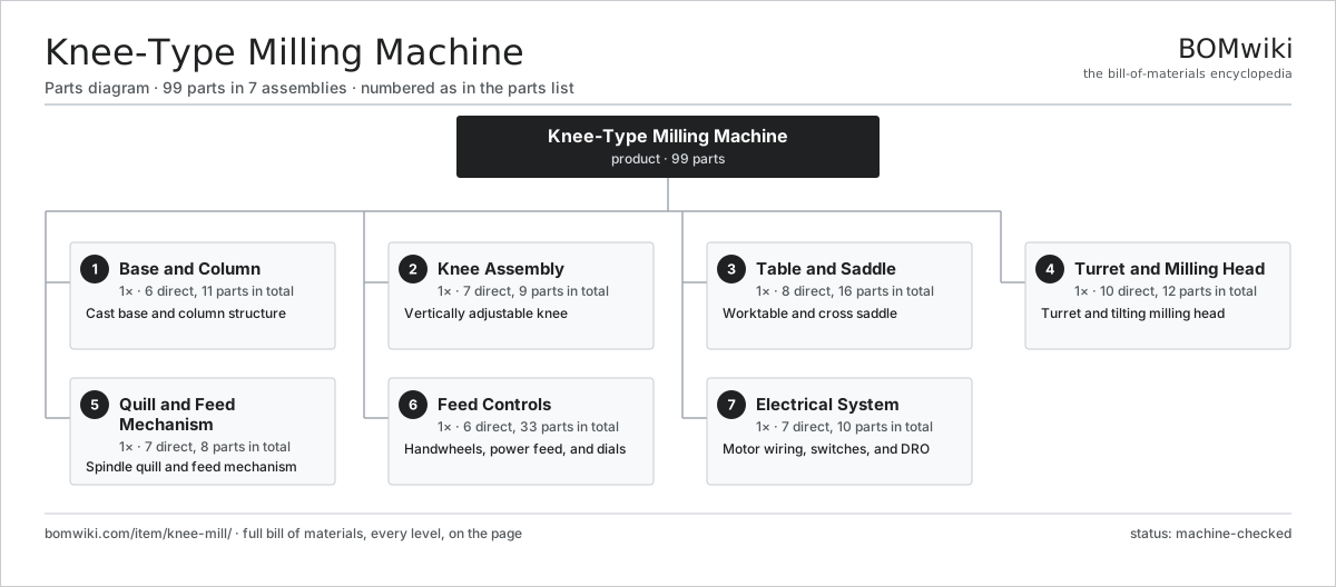
| # | Part | Qty | What it does |
|---|---|---|---|
| 1 | Base and Column 6 parts | 1× | Cast base and column structure |
| 2 | Knee Assembly 7 parts | 1× | Vertically adjustable knee |
| 3 | Table and Saddle 8 parts | 1× | Worktable and cross saddle |
| 4 | Turret and Milling Head 10 parts | 1× | Turret and tilting milling head |
| 5 | Quill and Feed Mechanism 7 parts | 1× | Spindle quill and feed mechanism |
| 6 | Feed Controls 6 parts | 1× | Handwheels, power feed, and dials |
| 7 | Electrical System 7 parts | 1× | Motor wiring, switches, and DRO |
3D model
No 3D model yet. Have a CAD file of this? Add a 3D model — STL renders right on this page; STEP, FreeCAD, and OpenSCAD sources are welcome too (openly licensed, like all 3D models on BOMwiki).
Build & assembly graph
expand / collapse · shared sub-assemblies converge · links to related products · est. labourTap an assembly to expand/collapse · tap a part to open it · use “Open page” for any node · drag to pan, scroll to zoom.
Bill of materials for Knee-Type Milling Machine
7 top-level lines · 62 rows shown · 99 parts total · indented to 3 levels| # | Item / sub-assembly | Part no. | Qty/assy | Ext. qty | Parts | Type |
|---|---|---|---|---|---|---|
| 1 | Base and Column 6 parts | km-base-column | 1× | 1 | 11 | assembly |
| 1.1 | Base Casting | km-base-casting | 1× | 1 | · | part |
| 1.2 | Column Casting | km-column-casting | 1× | 1 | · | part |
| 1.3 | Column Way | km-column-way | 2× | 2 | · | part |
| 1.4 | Gib Strip | km-gib-strip | 2× | 2 | · | part |
| 1.5 | Leveling Pad | km-leveling-pad | 4× | 4 | · | part |
| 1.6 | Fastener Set | fastener-set | 1× | 1 | · | part |
| 2 | Knee Assembly 7 parts | km-knee-assembly | 1× | 1 | 9 | assembly |
| 2.1 | Knee Casting | km-knee-casting | 1× | 1 | · | part |
| 2.2 | Elevating Screw | km-elevating-screw | 1× | 1 | · | part |
| 2.3 | Elevating Crank | km-elevating-crank | 1× | 1 | · | part |
| 2.4 | Knee Way | km-knee-way | 2× | 2 | · | part |
| 2.5 | Knee Lock | km-knee-lock | 1× | 1 | · | part |
| 2.6 | Ball Bearing | ball-bearing | 2× | 2 | · | part |
| 2.7 | O-Ring Set | oring-set | 1× | 1 | · | part |
| 3 | Table and Saddle 8 parts | km-table-saddle | 1× | 1 | 16 | assembly |
| 3.1 | Worktable | km-worktable | 1× | 1 | · | part |
| 3.2 | Saddle | km-saddle | 1× | 1 | · | part |
| 3.3 | Table Lead Screw | km-table-screw | 1× | 1 | · | part |
| 3.4 | Cross Lead Screw | km-cross-screw | 1× | 1 | · | part |
| 3.5 | Table Way | km-table-way | 2× | 2 | · | part |
| 3.6 | Table Stop | km-table-stop | 2× | 2 | · | part |
| 3.7 | Way Wiper | km-way-wiper | 4× | 4 | · | part |
| 3.8 | Ball Bearing | ball-bearing | 4× | 4 | · | part |
| 4 | Turret and Milling Head 10 parts | km-turret-head | 1× | 1 | 12 | assembly |
| 4.1 | Turret | km-turret | 1× | 1 | · | part |
| 4.2 | Ram | km-ram | 1× | 1 | · | part |
| 4.3 | Head Body | km-head-body | 1× | 1 | · | part |
| 4.4 | Spindle | km-spindle | 1× | 1 | · | part |
| 4.5 | Head Motor | km-head-motor | 1× | 1 | · | part |
| 4.6 | Drive Belt | drive-belt | 1× | 1 | · | part |
| 4.7 | Spindle Taper | km-spindle-taper | 1× | 1 | · | part |
| 4.8 | Drawbar | km-drawbar | 1× | 1 | · | part |
| 4.9 | Ball Bearing | ball-bearing | 3× | 3 | · | part |
| 4.10 | Oil Seal | oil-seal | 1× | 1 | · | part |
| 5 | Quill and Feed Mechanism 7 parts | km-quill-feed | 1× | 1 | 8 | assembly |
| 5.1 | Quill | km-quill | 1× | 1 | · | part |
| 5.2 | Quill Feed Lever | km-quill-feed-lever | 1× | 1 | · | part |
| 5.3 | Fine Feed Handwheel | km-fine-feed | 1× | 1 | · | part |
| 5.4 | Quill Stop | km-quill-stop | 1× | 1 | · | part |
| 5.5 | Quill Return Spring | km-quill-return | 1× | 1 | · | part |
| 5.6 | Helical Gear Pair | gear-pair | 1× | 1 | · | part |
| 5.7 | Ball Bearing | ball-bearing | 2× | 2 | · | part |
| 6 | Feed Controls 6 parts | km-feed-controls | 1× | 1 | 33 | assembly |
| 6.1 | Handwheel | km-handwheel | 3× | 3 | · | part |
| 6.2 | Power Feed | km-power-feed | 1× | 1 | · | part |
| 6.3 | Feed Gearbox | km-feed-gearbox | 1× | 1 | · | part |
| 6.4 | Servo Motor 4 parts | servo-motor | 1× | 1 | 24 | assembly |
| 6.4.1 | Stator Assembly 3 parts + deeper › | stator-assembly | 1× | 1 | 3 | assembly |
| 6.4.2 | Rotor Assembly 4 parts + deeper › | rotor-assembly | 1× | 1 | 19 | assembly |
| 6.4.3 | Encoder | encoder | 1× | 1 | · | part |
| 6.4.4 | Motor Housing | motor-housing | 1× | 1 | · | part |
| 6.5 | Dial Collar | km-dial-collar | 3× | 3 | · | part |
| 6.6 | Helical Gear Pair | gear-pair | 1× | 1 | · | part |
| 7 | Electrical System 7 parts | km-electrical | 1× | 1 | 10 | assembly |
| 7.1 | Motor Starter | km-starter | 1× | 1 | · | part |
| 7.2 | DRO Display | km-dro-display | 1× | 1 | · | part |
| 7.3 | DRO Scale | km-dro-scale | 3× | 3 | · | part |
| 7.4 | Control Switch | km-control-switch | 2× | 2 | · | part |
| 7.5 | Emergency Stop | km-estop | 1× | 1 | · | part |
| 7.6 | Work Light | km-work-light | 1× | 1 | · | part |
| 7.7 | Wire Bundle | wire-bundle | 1× | 1 | · | part |
Related products
same domain, ranked by shared parts Bevel Gear Generator
201 parts · shares 4 with this page
Cold Rolling Mill
991 parts · shares 4 with this page
Bevel Gear Generator
201 parts · shares 4 with this page
Cold Rolling Mill
991 parts · shares 4 with this page
 Crankshaft Grinder
511 parts · shares 4 with this page
Crankshaft Grinder
511 parts · shares 4 with this page
 Creep-Feed Grinder
571 parts · shares 4 with this page
Drag Finishing Machine
735 parts · shares 4 with this page
Creep-Feed Grinder
571 parts · shares 4 with this page
Drag Finishing Machine
735 parts · shares 4 with this page
Sourcing: possible vendors
Prices, MOQ, and lead times are algorithmic estimates, not quotes, and not claims about these companies. Company mappings are curated by keyword; est. price band $10k–$1M. How estimates work| Vendor | HQ | Specialty | MOQ | Lead time |
|---|---|---|---|---|
|
🇩🇪DMG MORI
dmgmori.com ↗
|
Bielefeld, DE | Machine tools | 5 units | 12–20 wks |
|
🇯🇵Mazak
mazak.com ↗
|
Oguchi, JP | Machine tools | 5 units | 12–20 wks |
| haascnc.com ↗ | Oxnard, US | CNC machine tools | 5 units | 12–20 wks |
|
🇯🇵Okuma
okuma.com ↗
|
Niwa, JP | Machine tools | 5 units | 12–20 wks |
|
🇩🇪Trumpf
trumpf.com ↗
|
Ditzingen, DE | Laser & sheet-metal machines | 5 units | 12–20 wks |
1,004-word article