Strip Tension Leveler
ProductOverview
A strip tension leveler removes shape defects from metal strip by stretching it past its yield point while it is bent over small-diameter rolls. Ordinary roller levelers only flex the strip, so they push down peaks and ripples but leave internal stresses that spring back over time. A tension leveler combines two actions at once: high longitudinal tension supplied by Bridle System bridles, and repeated reverse bending through Leveling Unit. The combination drives every fiber across the width into the plastic region, so when the strip leaves the line it has a uniform permanent length across its width and lies genuinely flat rather than appearing flat under load.
The line is built around the principle that flatness defects (edge wave, center buckle, crossbow, coil set) are differences in fiber length across or along the strip. By stretching the whole strip by a controlled 0.3 to 2.0 percent, the shorter fibers are pulled up to the length of the longer ones, and the differences disappear. The amount of stretch is set precisely because too little leaves residual defects and too much necks or breaks the strip. Cold-rolled steel, stainless, aluminum and coated products all run on the same line with recipe changes for tension, intermesh depth and roll diameter.
Entry and tension build-up
The coil is loaded by the Coil Loading Car onto the Expanding Mandrel of the Uncoiler, which pays the strip off under back-tension regulated by a Servo Motor. The strip passes the Strip Edge Guide, which keeps it centered using Edge Position Sensor feedback, then enters the Entry Bridle. A bridle is a cluster of Bridle Roll rolls that the strip wraps; because the rolls are driven at slightly different speeds and torques, friction between strip and roll surface lets them hold the strip in tension without slipping. The differential torque between entry and exit bridles is what creates the stretching force across the leveler. Live tension is read by the Tensiometer Roll so the controller always knows the true force in the strip.
Leveling unit
The Leveling Unit carries the small Leveling Work Roll rolls that bend the strip alternately up and down. Small diameter is essential: a thin roll bends the strip sharply over a short arc, which is what drives the surface fibers into yield at modest tension. Because such a slender roll would deflect under load, each is supported by a row of Backup Roll rolls held in the Cassette Frame. The whole Bending Roll Cassette is a quick-change unit so roll sets can be swapped for different products using the Cassette Change Cradle.
Penetration depth, how far the upper rolls reach down between the lower rolls, is set by the Intermesh Adjustment Actuator through an Intermesh Cylinder and a fine Adjustment Wedge Block, with position read back by a Roll Position Transducer. Deeper intermesh means sharper bending and more plastic work. Transverse curvature is corrected separately by the Anti-Crossbow Roll Set set, whose Crossbow Roll is bent across the width by a Roll Bending Cylinder to cancel crossbow without affecting longitudinal flatness.
Tension drive and hydraulics
Holding steady differential torque across all the bridles and reels is done electrically by the Tension Drive System. Each reel and bridle runs on a regenerative AC Drive tied to a Common DC Bus, so energy from a decelerating reel feeds the accelerating bridles instead of being burned off, with surplus absorbed by a Dynamic Brake Resistor. The drives live in a cooled Drive Cabinet. Mechanical setting forces come from the Hydraulic Power Unit: an Axial Piston Pump feeds a Valve Manifold of Proportional Valve valves that position the intermesh cylinders and expand the reel mandrels, with Bladder Accumulator units giving fast response and an Oil Cooler holding oil temperature.
Exit, measurement and rewinding
After leveling, the strip passes the Flatness Gauge, whose Shape Measuring Roll maps residual flatness so the operator can trim the recipe, then enters the Exit Bridle and the Recoiler. The Belt Wrapper starts the new coil onto the recoiler mandrel, after which the reel winds the flat strip under controlled tension. The Elongation Meter continuously compares the speeds of the Encoder Measuring Roll rolls at entry and exit; the speed difference is the permanent elongation, and it is the primary feedback for the whole process.
Control and structure
The Control System runs the elongation loop on the Line PLC, taking tension from the load cells and elongation from the speed measurement, and adjusting bridle torque and intermesh depth to hold the target stretch. The operator works through the Operator HMI, selecting product recipes that store all setup values. All of this is carried on the Machine Frame, whose Roll Stand Housing castings and heavy Base Frame resist the large roll-separating and tension forces while keeping roll alignment stable over long campaigns.
Materials and variants
Work rolls are tool steel hardened to around 60 HRC because they see millions of high-stress bending cycles; bridle rolls are chrome plated for friction and wear life. Lighter lines for aluminum and tinplate use lower tensions and larger work rolls, while heavy lines for high-strength steel use the smallest rolls and the deepest intermesh. Many tension levelers are integrated into coating, pickling or cut-to-length lines rather than running standalone, in which case the entry and exit reels are replaced by the upstream and downstream sections of the host line.
Strip Tension Leveler parts and their functions
8 top-level parts · 513 parts in total · full bill of materials below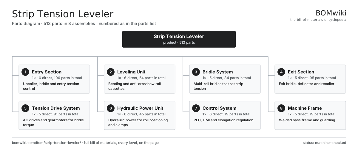
| # | Part | Qty | What it does |
|---|---|---|---|
| 1 | Entry Section 6 parts | 1× | Uncoiler, bridle and entry tension control |
| 2 | Leveling Unit 6 parts | 1× | Bending and anti-crossbow roll cassettes |
| 3 | Bridle System 5 parts | 1× | Multi-roll bridles that set strip tension |
| 4 | Exit Section 5 parts | 1× | Exit bridle, deflector and recoiler |
| 5 | Tension Drive System 5 parts | 1× | AC drives and gearmotors for bridle torque |
| 6 | Hydraulic Power Unit 6 parts | 1× | Hydraulic power for roll positioning and clamps |
| 7 | Control System 6 parts | 1× | PLC, HMI and elongation regulation |
| 8 | Machine Frame 5 parts | 1× | Welded base frame and guarding |
3D model
No 3D model yet. Have a CAD file of this? Add a 3D model — STL renders right on this page; STEP, FreeCAD, and OpenSCAD sources are welcome too (openly licensed, like all 3D models on BOMwiki).
Build & assembly graph
expand / collapse · shared sub-assemblies converge · links to related products · est. labourTap an assembly to expand/collapse · tap a part to open it · use “Open page” for any node · drag to pan, scroll to zoom.
Bill of materials for Strip Tension Leveler
8 top-level lines · 128 rows shown · 513 parts total · indented to 3 levels| # | Item / sub-assembly | Part no. | Qty/assy | Ext. qty | Parts | Type |
|---|---|---|---|---|---|---|
| 1 | Entry Section 6 parts | stl-entry-section | 1× | 1 | 106 | assembly |
| 1.1 | Uncoiler 6 parts | stl-uncoiler | 1× | 1 | 30 | assembly |
| 1.1.1 | Expanding Mandrel | stl-mandrel | 1× | 1 | · | part |
| 1.1.2 | Mandrel Expansion Cylinder | stl-mandrel-cylinder | 1× | 1 | · | part |
| 1.1.3 | Uncoiler Gearbox | stl-uncoiler-gearbox | 1× | 1 | · | part |
| 1.1.4 | Servo Motor 4 parts + deeper › | servo-motor | 1× | 1 | 24 | assembly |
| 1.1.5 | Ball Bearing | ball-bearing | 2× | 2 | · | part |
| 1.1.6 | Coil Loading Car | stl-coil-car | 1× | 1 | · | part |
| 1.2 | Entry Bridle 4 parts | stl-entry-bridle | 1× | 1 | 60 | assembly |
| 1.2.1 | Bridle Roll | stl-bridle-roll | 3× | 3 | · | part |
| 1.2.2 | Bridle Bearing Block 3 parts + deeper › | stl-bridle-bearing-block | 6× | 6 | 4 | assembly |
| 1.2.3 | Helical Gearbox 4 parts + deeper › | gearbox | 1× | 1 | 9 | assembly |
| 1.2.4 | Servo Motor 4 parts + deeper › | servo-motor | 1× | 1 | 24 | assembly |
| 1.3 | Strip Edge Guide 3 parts | stl-edge-guide | 1× | 1 | 5 | assembly |
| 1.3.1 | Guide Roll | stl-guide-roll | 2× | 2 | · | part |
| 1.3.2 | Edge Position Sensor | stl-edge-sensor | 2× | 2 | · | part |
| 1.3.3 | Guide Positioning Actuator | stl-guide-actuator | 1× | 1 | · | part |
| 1.4 | Pinch Roll Unit 4 parts | stl-pinch-roll | 1× | 1 | 8 | assembly |
| 1.4.1 | Lower Pinch Roll | stl-pinch-roll-lower | 1× | 1 | · | part |
| 1.4.2 | Upper Pinch Roll | stl-pinch-roll-upper | 1× | 1 | · | part |
| 1.4.3 | Pneumatic Cylinder | pneumatic-cylinder | 2× | 2 | · | part |
| 1.4.4 | Ball Bearing | ball-bearing | 4× | 4 | · | part |
| 1.5 | Deflector Roll | stl-deflector-roll | 2× | 2 | · | part |
| 1.6 | Snubber Roll | stl-snubber-roll | 1× | 1 | · | part |
| 2 | Leveling Unit 6 parts | stl-leveling-unit | 1× | 1 | 54 | assembly |
| 2.1 | Bending Roll Cassette 4 parts | stl-bending-cassette | 1× | 1 | 33 | assembly |
| 2.1.1 | Leveling Work Roll | stl-work-roll | 8× | 8 | · | part |
| 2.1.2 | Backup Roll | stl-backup-roll | 8× | 8 | · | part |
| 2.1.3 | Cassette Frame | stl-cassette-frame | 1× | 1 | · | part |
| 2.1.4 | Ball Bearing | ball-bearing | 16× | 16 | · | part |
| 2.2 | Intermesh Adjustment Actuator 3 parts | stl-intermesh-actuator | 2× | 2 | 3 | assembly |
| 2.2.1 | Intermesh Cylinder | stl-intermesh-cylinder | 1× | 2 | · | part |
| 2.2.2 | Roll Position Transducer | stl-position-transducer | 1× | 2 | · | part |
| 2.2.3 | Adjustment Wedge Block | stl-wedge-block | 1× | 2 | · | part |
| 2.3 | Anti-Crossbow Roll Set 3 parts | stl-anticrossbow-roll | 1× | 1 | 8 | assembly |
| 2.3.1 | Crossbow Roll | stl-crossbow-roll | 2× | 2 | · | part |
| 2.3.2 | Roll Bending Cylinder | stl-roll-bending-cylinder | 2× | 2 | · | part |
| 2.3.3 | Ball Bearing | ball-bearing | 4× | 4 | · | part |
| 2.4 | Flattener Backing Roll | stl-flattener-roll | 4× | 4 | · | part |
| 2.5 | Roll Bending Cylinder | stl-roll-bending-cylinder | 2× | 2 | · | part |
| 2.6 | Cassette Change Cradle | stl-cassette-changer | 1× | 1 | · | part |
| 3 | Bridle System 5 parts | stl-bridle-system | 1× | 1 | 84 | assembly |
| 3.1 | Bridle Roll | stl-bridle-roll | 6× | 6 | · | part |
| 3.2 | Tensiometer Roll 3 parts | stl-load-cell-roll | 2× | 2 | 5 | assembly |
| 3.2.1 | Deflector Roll | stl-deflector-roll | 1× | 2 | · | part |
| 3.2.2 | Tension Load Cell | stl-load-cell | 2× | 4 | · | part |
| 3.2.3 | Ball Bearing | ball-bearing | 2× | 4 | · | part |
| 3.3 | Helical Gearbox 4 parts | gearbox | 2× | 2 | 9 | assembly |
| 3.3.1 | Helical Gear Pair | gear-pair | 2× | 4 | · | part |
| 3.3.2 | Gearbox Housing | gearbox-housing | 1× | 2 | · | part |
| 3.3.3 | Ball Bearing | ball-bearing | 4× | 8 | · | part |
| 3.3.4 | Oil Seal | oil-seal | 2× | 4 | · | part |
| 3.4 | Bridle Bearing Block 3 parts | stl-bridle-bearing-block | 12× | 12 | 4 | assembly |
| 3.4.1 | Ball Bearing | ball-bearing | 1× | 12 | · | part |
| 3.4.2 | Oil Seal | oil-seal | 2× | 24 | · | part |
| 3.4.3 | Fastener Set | fastener-set | 1× | 12 | · | part |
| 3.5 | Drive Belt | drive-belt | 2× | 2 | · | part |
| 4 | Exit Section 5 parts | stl-exit-section | 1× | 1 | 95 | assembly |
| 4.1 | Exit Bridle 4 parts | stl-exit-bridle | 1× | 1 | 60 | assembly |
| 4.1.1 | Bridle Roll | stl-bridle-roll | 3× | 3 | · | part |
| 4.1.2 | Bridle Bearing Block 3 parts + deeper › | stl-bridle-bearing-block | 6× | 6 | 4 | assembly |
| 4.1.3 | Helical Gearbox 4 parts + deeper › | gearbox | 1× | 1 | 9 | assembly |
| 4.1.4 | Servo Motor 4 parts + deeper › | servo-motor | 1× | 1 | 24 | assembly |
| 4.2 | Recoiler 5 parts | stl-recoiler | 1× | 1 | 29 | assembly |
| 4.2.1 | Expanding Mandrel | stl-mandrel | 1× | 1 | · | part |
| 4.2.2 | Mandrel Expansion Cylinder | stl-mandrel-cylinder | 1× | 1 | · | part |
| 4.2.3 | Recoiler Gearbox | stl-recoiler-gearbox | 1× | 1 | · | part |
| 4.2.4 | Servo Motor 4 parts + deeper › | servo-motor | 1× | 1 | 24 | assembly |
| 4.2.5 | Ball Bearing | ball-bearing | 2× | 2 | · | part |
| 4.3 | Exit Deflector Roll | stl-exit-deflector | 2× | 2 | · | part |
| 4.4 | Flatness Gauge 3 parts | stl-flatness-gauge | 1× | 1 | 3 | assembly |
| 4.4.1 | Shape Measuring Roll | stl-shape-sensor | 1× | 1 | · | part |
| 4.4.2 | Bare PCB | pcb-bare | 1× | 1 | · | part |
| 4.4.3 | Microcontroller | mcu | 1× | 1 | · | part |
| 4.5 | Belt Wrapper | stl-belt-wrapper | 1× | 1 | · | part |
| 5 | Tension Drive System 5 parts | stl-tension-drive | 1× | 1 | 91 | assembly |
| 5.1 | AC Drive 4 parts | stl-ac-drive | 6× | 6 | 12 | assembly |
| 5.1.1 | Bare PCB | pcb-bare | 1× | 6 | · | part |
| 5.1.2 | IGBT Power Module | igbt-module | 6× | 36 | · | part |
| 5.1.3 | DC-Link Capacitor | dc-link-cap | 4× | 24 | · | part |
| 5.1.4 | Microcontroller | mcu | 1× | 6 | · | part |
| 5.2 | Drive Cabinet 4 parts | stl-drive-cabinet | 1× | 1 | 10 | assembly |
| 5.2.1 | Sheet Metal Panel | sheet-panel | 6× | 6 | · | part |
| 5.2.2 | Power Supply | power-supply | 1× | 1 | · | part |
| 5.2.3 | Cabinet Cooling Fan | stl-cabinet-fan | 2× | 2 | · | part |
| 5.2.4 | Fastener Set | fastener-set | 1× | 1 | · | part |
| 5.3 | Line Reactor | stl-line-reactor | 6× | 6 | · | part |
| 5.4 | Dynamic Brake Resistor | stl-brake-resistor | 2× | 2 | · | part |
| 5.5 | Common DC Bus | stl-dc-bus | 1× | 1 | · | part |
| 6 | Hydraulic Power Unit 6 parts | stl-hydraulic-unit | 1× | 1 | 45 | assembly |
| 6.1 | Hydraulic Pump 3 parts | stl-hydraulic-pump | 1× | 1 | 26 | assembly |
| 6.1.1 | Axial Piston Pump | stl-piston-pump | 1× | 1 | · | part |
| 6.1.2 | Servo Motor 4 parts + deeper › | servo-motor | 1× | 1 | 24 | assembly |
| 6.1.3 | O-Ring Set | oring-set | 1× | 1 | · | part |
| 6.2 | Hydraulic Reservoir 3 parts | stl-hydraulic-tank | 1× | 1 | 3 | assembly |
| 6.2.1 | Reservoir Shell | stl-tank-shell | 1× | 1 | · | part |
| 6.2.2 | Return Line Filter | stl-return-filter | 1× | 1 | · | part |
| 6.2.3 | Oil Level Switch | stl-level-switch | 1× | 1 | · | part |
| 6.3 | Valve Manifold 3 parts | stl-valve-manifold | 1× | 1 | 9 | assembly |
| 6.3.1 | Proportional Valve | stl-proportional-valve | 4× | 4 | · | part |
| 6.3.2 | Check Valve | stl-check-valve | 4× | 4 | · | part |
| 6.3.3 | O-Ring Set | oring-set | 1× | 1 | · | part |
| 6.4 | Bladder Accumulator | stl-accumulator | 2× | 2 | · | part |
| 6.5 | Oil Cooler | stl-oil-cooler | 1× | 1 | · | part |
| 6.6 | Pressure Sensor | pressure-sensor | 4× | 4 | · | part |
| 7 | Control System 6 parts | stl-control-system | 1× | 1 | 19 | assembly |
| 7.1 | Line PLC 4 parts | stl-plc | 1× | 1 | 8 | assembly |
| 7.1.1 | Bare PCB | pcb-bare | 1× | 1 | · | part |
| 7.1.2 | Microcontroller | mcu | 2× | 2 | · | part |
| 7.1.3 | PLC I/O Module | stl-io-module | 4× | 4 | · | part |
| 7.1.4 | Power Supply | power-supply | 1× | 1 | · | part |
| 7.2 | Operator HMI 3 parts | stl-hmi | 1× | 1 | 3 | assembly |
| 7.2.1 | LCD Panel | lcd-panel | 1× | 1 | · | part |
| 7.2.2 | Bare PCB | pcb-bare | 1× | 1 | · | part |
| 7.2.3 | Microcontroller | mcu | 1× | 1 | · | part |
| 7.3 | Remote I/O Rack | stl-io-rack | 2× | 2 | · | part |
| 7.4 | Elongation Meter 3 parts | stl-elongation-meter | 1× | 1 | 4 | assembly |
| 7.4.1 | Encoder Measuring Roll | stl-encoder-roll | 2× | 2 | · | part |
| 7.4.2 | Microcontroller | mcu | 1× | 1 | · | part |
| 7.4.3 | Bare PCB | pcb-bare | 1× | 1 | · | part |
| 7.5 | Control Power Supply | stl-control-power | 1× | 1 | · | part |
| 7.6 | Wire Bundle | wire-bundle | 1× | 1 | · | part |
| 8 | Machine Frame 5 parts | stl-frame | 1× | 1 | 19 | assembly |
| 8.1 | Base Frame | stl-base-frame | 1× | 1 | · | part |
| 8.2 | Roll Stand Housing | stl-roll-housing | 2× | 2 | · | part |
| 8.3 | Safety Guard Panel | stl-guard-panel | 6× | 6 | · | part |
| 8.4 | Maintenance Walkway | stl-walkway | 2× | 2 | · | part |
| 8.5 | Leveling Foot | stl-leveling-foot | 8× | 8 | · | part |
Related products
same domain, ranked by shared parts Compression Spring Coiler
1,167 parts · shares 7 with this page
Compression Spring Coiler
1,167 parts · shares 7 with this page
Sourcing: possible vendors
Prices, MOQ, and lead times are algorithmic estimates, not quotes, and not claims about these companies. Company mappings are curated by keyword; est. price band $10k–$1M. How estimates work| Vendor | HQ | Specialty | MOQ | Lead time |
|---|---|---|---|---|
|
🇩🇪DMG MORI
dmgmori.com ↗
|
Bielefeld, DE | Machine tools | 5 units | 12–20 wks |
|
🇯🇵Mazak
mazak.com ↗
|
Oguchi, JP | Machine tools | 5 units | 12–20 wks |
| haascnc.com ↗ | Oxnard, US | CNC machine tools | 5 units | 12–20 wks |
|
🇯🇵Okuma
okuma.com ↗
|
Niwa, JP | Machine tools | 5 units | 12–20 wks |
|
🇩🇪Trumpf
trumpf.com ↗
|
Ditzingen, DE | Laser & sheet-metal machines | 5 units | 12–20 wks |
930-word article