Wire EDM Machine
ProductOverview
A wire EDM machine cuts hardened steel, carbide, and other conductive metals without touching them with a cutting edge. Instead of a blade or a grinding wheel, it uses a thin traveling wire as one electrode and the workpiece as the other, and it removes metal by firing a stream of tiny electrical sparks across the gap between them. Because there is no mechanical cutting force, the machine can cut shapes that would be impossible to mill or grind: thin webs, sharp internal corners, and fully hardened tool steel that would wreck a milling cutter. It is the standard way to make stamping dies, injection-mould inserts, extrusion dies, and precision gauges, and it works to a few microns on parts up to several hundred millimetres thick.
The wire is consumed as it cuts. Fresh wire pays off a spool, runs down through the cut once, and is chopped into scrap, so the wire that does the cutting is always clean and round. The whole cut takes place underwater, in a tank of deionized water that acts as the spark medium and as the coolant. The major subsystems are the Wire Transport System that moves the wire, the Upper Guide Head and Lower Guide Arm that guide it and feed power into it, the Spark Generator that creates the discharges, the Dielectric System that conditions the water, the Axis Drives that move the workpiece, the Work Tank and Worktable that holds it, the Automatic Wire Threader that rethreads after a break, and the Control Cabinet that runs the cycle.
How EDM Cutting Works
Each cut is made by thousands of separate sparks per second, not by a continuous current. The Spark Generator charges the gap between wire and workpiece until the deionized water breaks down and a spark jumps across. That spark reaches several thousand degrees and melts and vaporises a microscopic crater of metal. The Pulse Switching Board then switches the gap off, the water flushes the molten debris away and cools the crater, and the cycle repeats. A Gap Sensing Board watches the gap voltage on every pulse, so the control can tell an open gap from a short and adjust the feed to keep the wire at the ignition distance, usually a few tens of microns from the work.
The pulse-on time and pulse-off time set the trade between speed and finish. Long, energetic pulses cut fast but leave a rough, recast surface; short pulses with a Power MOSFET Bank delivering controlled peak current leave a fine finish and are used for the final skim passes. A part is often rough-cut once and then skimmed two or three more times along the same path, each pass taking less metal and improving the surface and accuracy.
Wire Transport
The Wire Transport System keeps a fresh length of wire in the cut at all times. The EDM Wire is brass or zinc-coated brass, 0.1 to 0.3 mm in diameter, wound on a Wire Supply Spool that can hold many kilograms. The wire is paid off against a Wire Tension Brake that holds it under steady tension so it runs straight and does not bow away from the spark. Below the cut a Capstan Drive pulls the wire through at 1 to 15 m/min, and a Wire Chopper cuts the used wire into short pieces that drop into the Scrap Wire Bin for recycling. Constant tension and constant speed matter because any wobble in the wire shows up directly as an error in the cut.
Dielectric System
The Dielectric System supplies and conditions the deionized water that makes the process work. The water has to be the right resistivity: too conductive and the gap will not hold a charge, too pure and ignition is slow. A Deionizer Resin Bottle of ion-exchange resin pulls dissolved ions out of the water to hold resistivity around 50 to 100 kohm-cm, and a Resistivity Sensor switches the deionizer in and out to keep it in band. A Dielectric Pump drives the water through the Upper Flushing Nozzle and Lower Flushing Nozzle at 5 to 15 bar to flush eroded particles out of the cut, which is essential on thick sections where debris would otherwise cause unstable sparks. A Particle Filter removes that debris down to a few microns before the water returns, and a Dielectric Chiller holds the water within about a kelvin of machine temperature so thermal growth does not spoil accuracy.
Axes and Guides
The contour comes from moving the workpiece, not the wire. The Axis Drives carry the table in X and Y on the X-Axis Slide and Y-Axis Slide, each closed by a Axis Glass Scale reading position to 0.1 micron, so the machine works to measured position rather than ball-screw count. The wire itself is located by the Upper Wire Guide and Lower Wire Guide, precision diamond or sapphire die guides matched to the wire diameter; these set the gap geometry and are the parts that most directly fix cut accuracy. Power enters the wire through carbide Power Feed Contact pieces in each head, which erode from arcing and are indexed to a fresh face periodically.
For tapered cuts the Upper Guide Head rides on the U/V Taper Slide, a U/V cross-slide that offsets the top guide from the bottom one so the wire leans at an angle. By interpolating U and V with X and Y the machine cuts tapers up to 15 to 30 degrees and four-axis shapes where the top and bottom profiles differ, such as a die that is one contour on top and another below.
Control and Threading
The Control Cabinet ties everything together. The CNC Controller interpolates all four axes, picks technology settings from material and thickness tables, and adapts feed to the gap feedback so the wire does not stall or break mid-cut. When a wire does break, or when a separate detail starts from a drilled hole, the Automatic Wire Threader handles it automatically. The AWT Cut-Off Unit trims the wire end, the AWT Annealer straightens it, and the AWT Water Injector floats it down through a start hole as small as 0.2 mm on a fine water jet before the AWT Feed Gripper feeds it to the capstan. Automatic wire threading lets a machine run a tray of parts unattended overnight.
Variants and Use
Most production wire EDM is done submerged, with the Work Tank and Worktable flooded above the workpiece, which gives the most stable cutting and the best flushing. Smaller and older machines run with the work in open air and flush only through the nozzles. Toolmakers use these machines to cut punch-and-die sets, carbide form tools, mould inserts, fir-tree slots in turbine discs, and fine medical and electronic parts, anywhere a hardened conductive material has to be cut to a few microns with sharp corners that grinding cannot reach.
Wire EDM Machine parts and their functions
9 top-level parts · 254 parts in total · full bill of materials below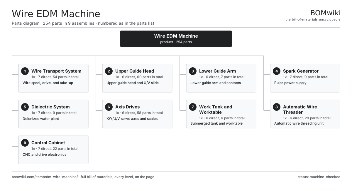
| # | Part | Qty | What it does |
|---|---|---|---|
| 1 | Wire Transport System 7 parts | 1× | Wire spool, drive, and take-up |
| 2 | Upper Guide Head 6 parts | 1× | Upper guide head and U/V slide |
| 3 | Lower Guide Arm 6 parts | 1× | Lower guide arm and contacts |
| 4 | Spark Generator 7 parts | 1× | Pulse power supply |
| 5 | Dielectric System 7 parts | 1× | Deionized water plant |
| 6 | Axis Drives 6 parts | 1× | X/Y/U/V servo axes and scales |
| 7 | Work Tank and Worktable 6 parts | 1× | Submerged tank and worktable |
| 8 | Automatic Wire Threader 6 parts | 1× | Automatic wire threading unit |
| 9 | Control Cabinet 7 parts | 1× | CNC and drive electronics |
3D model
No 3D model yet. Have a CAD file of this? Add a 3D model — STL renders right on this page; STEP, FreeCAD, and OpenSCAD sources are welcome too (openly licensed, like all 3D models on BOMwiki).
Build & assembly graph
expand / collapse · shared sub-assemblies converge · links to related products · est. labourTap an assembly to expand/collapse · tap a part to open it · use “Open page” for any node · drag to pan, scroll to zoom.
Bill of materials for Wire EDM Machine
9 top-level lines · 83 rows shown · 254 parts total · indented to 3 levels| # | Item / sub-assembly | Part no. | Qty/assy | Ext. qty | Parts | Type |
|---|---|---|---|---|---|---|
| 1 | Wire Transport System 7 parts | wedm-wire-transport | 1× | 1 | 54 | assembly |
| 1.1 | Wire Supply Spool | wedm-wire-spool | 1× | 1 | · | part |
| 1.2 | EDM Wire | wedm-wire | 1× | 1 | · | part |
| 1.3 | Wire Tension Brake | wedm-tension-brake | 1× | 1 | · | part |
| 1.4 | Capstan Drive | wedm-capstan-drive | 1× | 1 | · | part |
| 1.5 | Wire Chopper | wedm-wire-chopper | 1× | 1 | · | part |
| 1.6 | Scrap Wire Bin | wedm-take-up-bin | 1× | 1 | · | part |
| 1.7 | Servo Motor 4 parts | servo-motor | 2× | 2 | 24 | assembly |
| 1.7.1 | Stator Assembly 3 parts + deeper › | stator-assembly | 1× | 2 | 3 | assembly |
| 1.7.2 | Rotor Assembly 4 parts + deeper › | rotor-assembly | 1× | 2 | 19 | assembly |
| 1.7.3 | Encoder | encoder | 1× | 2 | · | part |
| 1.7.4 | Motor Housing | motor-housing | 1× | 2 | · | part |
| 2 | Upper Guide Head 6 parts | wedm-upper-head | 1× | 1 | 60 | assembly |
| 2.1 | Upper Wire Guide | wedm-upper-guide | 1× | 1 | · | part |
| 2.2 | Power Feed Contact | wedm-power-contact | 2× | 2 | · | part |
| 2.3 | Upper Flushing Nozzle | wedm-flush-nozzle-upper | 1× | 1 | · | part |
| 2.4 | U/V Taper Slide 4 parts | wedm-uv-slide | 1× | 1 | 54 | assembly |
| 2.4.1 | Ball Screw | ball-screw | 2× | 2 | · | part |
| 2.4.2 | Linear Guide Rail | linear-guide | 2× | 2 | · | part |
| 2.4.3 | Servo Motor 4 parts + deeper › | servo-motor | 2× | 2 | 24 | assembly |
| 2.4.4 | U/V Glass Scale | wedm-uv-scale | 2× | 2 | · | part |
| 2.5 | Upper Guide Block | wedm-upper-guide-block | 1× | 1 | · | part |
| 2.6 | O-Ring Set | oring-set | 1× | 1 | · | part |
| 3 | Lower Guide Arm 6 parts | wedm-lower-head | 1× | 1 | 7 | assembly |
| 3.1 | Lower Wire Guide | wedm-lower-guide | 1× | 1 | · | part |
| 3.2 | Power Feed Contact | wedm-power-contact | 2× | 2 | · | part |
| 3.3 | Lower Flushing Nozzle | wedm-flush-nozzle-lower | 1× | 1 | · | part |
| 3.4 | Wire Turning Roller | wedm-turn-roller | 1× | 1 | · | part |
| 3.5 | Lower Guide Block | wedm-lower-guide-block | 1× | 1 | · | part |
| 3.6 | O-Ring Set | oring-set | 1× | 1 | · | part |
| 4 | Spark Generator 7 parts | wedm-spark-generator | 1× | 1 | 9 | assembly |
| 4.1 | Pulse Switching Board | wedm-pulse-board | 2× | 2 | · | part |
| 4.2 | Gap Sensing Board | wedm-gap-sense-board | 1× | 1 | · | part |
| 4.3 | Power MOSFET Bank | wedm-power-mosfet-bank | 1× | 1 | · | part |
| 4.4 | Power Supply | power-supply | 1× | 1 | · | part |
| 4.5 | Bare PCB | pcb-bare | 2× | 2 | · | part |
| 4.6 | Microcontroller | mcu | 1× | 1 | · | part |
| 4.7 | SMD Passive (R/C/L) | smd-passives | 1× | 1 | · | part |
| 5 | Dielectric System 7 parts | wedm-dielectric-system | 1× | 1 | 9 | assembly |
| 5.1 | Dielectric Pump | wedm-dielectric-pump | 2× | 2 | · | part |
| 5.2 | Deionizer Resin Bottle | wedm-deionizer-bottle | 1× | 1 | · | part |
| 5.3 | Particle Filter | wedm-particle-filter | 2× | 2 | · | part |
| 5.4 | Resistivity Sensor | wedm-resistivity-sensor | 1× | 1 | · | part |
| 5.5 | Dielectric Chiller | wedm-dielectric-chiller | 1× | 1 | · | part |
| 5.6 | Clean Water Tank | wedm-clean-tank | 1× | 1 | · | part |
| 5.7 | Dirty Water Tank | wedm-dirty-tank | 1× | 1 | · | part |
| 6 | Axis Drives 6 parts | wedm-axis-drives | 1× | 1 | 58 | assembly |
| 6.1 | X-Axis Slide | wedm-x-slide | 1× | 1 | · | part |
| 6.2 | Y-Axis Slide | wedm-y-slide | 1× | 1 | · | part |
| 6.3 | Axis Glass Scale | wedm-axis-scale | 2× | 2 | · | part |
| 6.4 | Ball Screw | ball-screw | 2× | 2 | · | part |
| 6.5 | Linear Guide Rail | linear-guide | 4× | 4 | · | part |
| 6.6 | Servo Motor 4 parts | servo-motor | 2× | 2 | 24 | assembly |
| 6.6.1 | Stator Assembly 3 parts + deeper › | stator-assembly | 1× | 2 | 3 | assembly |
| 6.6.2 | Rotor Assembly 4 parts + deeper › | rotor-assembly | 1× | 2 | 19 | assembly |
| 6.6.3 | Encoder | encoder | 1× | 2 | · | part |
| 6.6.4 | Motor Housing | motor-housing | 1× | 2 | · | part |
| 7 | Work Tank and Worktable 6 parts | wedm-work-tank | 1× | 1 | 6 | assembly |
| 7.1 | Work Tank Shell | wedm-tank-shell | 1× | 1 | · | part |
| 7.2 | Tank Door | wedm-tank-door | 1× | 1 | · | part |
| 7.3 | Worktable | wedm-worktable | 1× | 1 | · | part |
| 7.4 | Fill and Drain Valve | wedm-fill-drain-valve | 1× | 1 | · | part |
| 7.5 | Tank Level Sensor | wedm-level-sensor | 1× | 1 | · | part |
| 7.6 | O-Ring Set | oring-set | 1× | 1 | · | part |
| 8 | Automatic Wire Threader 6 parts | wedm-wire-threader | 1× | 1 | 29 | assembly |
| 8.1 | AWT Cut-Off Unit | wedm-awt-cutter | 1× | 1 | · | part |
| 8.2 | AWT Annealer | wedm-awt-annealer | 1× | 1 | · | part |
| 8.3 | AWT Water Injector | wedm-awt-injector | 1× | 1 | · | part |
| 8.4 | AWT Feed Gripper | wedm-awt-gripper | 1× | 1 | · | part |
| 8.5 | Servo Motor 4 parts | servo-motor | 1× | 1 | 24 | assembly |
| 8.5.1 | Stator Assembly 3 parts + deeper › | stator-assembly | 1× | 1 | 3 | assembly |
| 8.5.2 | Rotor Assembly 4 parts + deeper › | rotor-assembly | 1× | 1 | 19 | assembly |
| 8.5.3 | Encoder | encoder | 1× | 1 | · | part |
| 8.5.4 | Motor Housing | motor-housing | 1× | 1 | · | part |
| 8.6 | Pressure Sensor | pressure-sensor | 1× | 1 | · | part |
| 9 | Control Cabinet 7 parts | wedm-control-cabinet | 1× | 1 | 22 | assembly |
| 9.1 | CNC Controller | wedm-cnc-unit | 1× | 1 | · | part |
| 9.2 | Servo Drive | wedm-servo-drive | 4× | 4 | · | part |
| 9.3 | Power Supply | power-supply | 1× | 1 | · | part |
| 9.4 | Operator Panel | wedm-operator-panel | 1× | 1 | · | part |
| 9.5 | Relay | relay | 6× | 6 | · | part |
| 9.6 | Wire Bundle | wire-bundle | 1× | 1 | · | part |
| 9.7 | Connector | connector | 8× | 8 | · | part |
Related products
same domain, ranked by shared parts Bevel Gear Generator
201 parts · shares 4 with this page
Camshaft Grinder
489 parts · shares 4 with this page
Centering and Facing Machine
1,419 parts · shares 4 with this page
Bevel Gear Generator
201 parts · shares 4 with this page
Camshaft Grinder
489 parts · shares 4 with this page
Centering and Facing Machine
1,419 parts · shares 4 with this page
 CNC Lathe
511 parts · shares 4 with this page
CNC Lathe
511 parts · shares 4 with this page
 CO2 Laser Cutting Machine
227 parts · shares 4 with this page
CO2 Laser Cutting Machine
227 parts · shares 4 with this page
Sourcing: possible vendors
Prices, MOQ, and lead times are algorithmic estimates, not quotes, and not claims about these companies. Company mappings are curated by keyword; est. price band $10k–$1M. How estimates work| Vendor | HQ | Specialty | MOQ | Lead time |
|---|---|---|---|---|
|
🇩🇪DMG MORI
dmgmori.com ↗
|
Bielefeld, DE | Machine tools | 5 units | 12–20 wks |
|
🇯🇵Mazak
mazak.com ↗
|
Oguchi, JP | Machine tools | 5 units | 12–20 wks |
| haascnc.com ↗ | Oxnard, US | CNC machine tools | 5 units | 12–20 wks |
|
🇯🇵Okuma
okuma.com ↗
|
Niwa, JP | Machine tools | 5 units | 12–20 wks |
|
🇩🇪Trumpf
trumpf.com ↗
|
Ditzingen, DE | Laser & sheet-metal machines | 5 units | 12–20 wks |
1,183-word article