Thread Grinding Machine
ProductOverview
A thread grinding machine cuts an accurate screw thread into a hardened part using a shaped abrasive wheel. Threads can be cut soft by single-point turning or thread milling, but those processes cannot hold close tolerance once the part is hardened, and hardening distorts the thread that was cut soft. Thread grinding solves this by forming the thread after heat treatment, grinding the flanks straight from the hardened blank or cleaning up a roughed thread. The result is the highest accuracy of pitch, flank angle and surface finish available, which is why the process makes thread plug and ring gauges, precision lead screws, ball-screw spindles, taps and aerospace fasteners.
The machine looks like a cylindrical grinder turned to a special job. The work sits between centers on the Bed & Ways, turned slowly by the Workhead while it moves along its axis on the Lead Axis. A wheel dressed to the thread profile sits in the Swivelling Wheelhead, which swivels so the wheel lies along the helix of the thread. As the work turns and travels, the wheel traces a helical groove of exactly the right form, pitch and depth.
How it works
The thread is generated by tying three motions together. The Work Drive Servo turns the work as a C axis; the Lead Axis moves it along its length; and the ratio between the two sets the pitch. For every full turn of the work the lead axis must advance exactly one pitch, and that ratio has to hold to a fraction of a micron over the whole length or the thread will drift off pitch. On this machine the lead axis runs a Ball Screw on a Linear Guide Rail, closed back to a Lead Axis Scale glass scale, and the CNC slaves it to the C-Axis Encoder on the workhead. Older machines used a physical Master Leadscrew and change gears to set the ratio mechanically; the master screw is still fitted here as a reference and for legacy thread forms.
The Swivelling Wheelhead is set on a graduated Swivel Base to the helix angle of the thread, then locked with the Swivel Clamp. Without this tilt the wheel would foul the flanks and grind a distorted form. Depth of thread is set by the Infeed Cross Slide slide, which feeds the whole wheelhead toward the work between passes, taking the thread to size over several passes for deep or coarse threads or in one pass for fine ones.
The wheel and its form
The Thread Grinding Wheel is the tool that defines the thread. A single-rib wheel carries one ground rib that matches the thread groove and grinds the thread one helical pass at a time; it gives the best form accuracy and is used for gauges and lead screws. A multi-rib wheel carries several ribs at the thread pitch and grinds the thread in roughly one plunge plus a short traverse, which is faster but slightly less accurate, and it suits production of taps and fasteners. Either way the wheel form wears, so the Thread-Form Dresser reshapes it. A diamond on the Dresser Slide is driven across the wheel under a Form Template or CNC profile to cut the exact flank angle and root radius back into the rib. Frequent dressing is what keeps the ground thread inside a two-micron pitch band.
Workholding and structure
The work runs between a center in the Workhead and a center in the Tailstock. The tailstock center sits on a spring-loaded Tailstock Quill so center pressure stays constant as the part heats and grows during grinding, which would otherwise bow a long screw or crush a short one. The work is turned through a Drive Plate & Dog plate so it cannot slip relative to the C-axis encoder. Everything mounts on the Cast Iron Bed, a stress-relieved iron casting on hardened, hand-scraped Hardened Slideway surfaces, because pitch accuracy depends directly on the straightness and stability of the bed.
Coolant and control
Grinding a hardened thread generates heat that can temper the surface or crack it, so the Coolant System system floods the contact with filtered fluid. The tank uses fine filtration because grit left in the coolant would score the ground flanks. The CNC Control runs the part program and keeps the C axis, lead axis and infeed in step; each axis has its own Servo Axis Drive. The operator enters thread diameter, pitch, form and length, and the control sets the swivel reference, the gear ratio between rotation and lead, the dressing cycle and the infeed schedule.
Variants and use
Small machines grind taps, dies and instrument screws; large machines grind ball-screw spindles and roll-thread dies metres long. Wheels are vitrified aluminium oxide for most steels or plated CBN for very hard or high-volume work, where the longer-lasting form cuts dressing frequency. The defining job remains gauges and lead screws, parts whose whole value is the accuracy of the thread, ground after hardening to a pitch and flank tolerance no other thread process reaches.
Thread Grinding Machine parts and their functions
10 top-level parts · 498 parts in total · full bill of materials below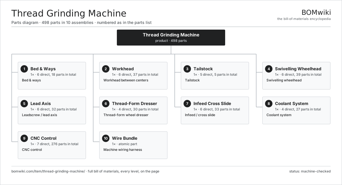
| # | Part | Qty | What it does |
|---|---|---|---|
| 1 | Bed & Ways 6 parts | 1× | Bed & ways |
| 2 | Workhead 6 parts | 1× | Workhead between centers |
| 3 | Tailstock 5 parts | 1× | Tailstock |
| 4 | Swivelling Wheelhead 6 parts | 1× | Swivelling wheelhead |
| 5 | Lead Axis 6 parts | 1× | Leadscrew / lead axis |
| 6 | Thread-Form Dresser 4 parts | 1× | Thread-form wheel dresser |
| 7 | Infeed Cross Slide 6 parts | 1× | Infeed / cross slide |
| 8 | Coolant System 4 parts | 1× | Coolant system |
| 9 | CNC Control 7 parts | 1× | CNC control |
| 10 | Wire Bundle | 1× | Machine wiring harness |
3D model
No 3D model yet. Have a CAD file of this? Add a 3D model — STL renders right on this page; STEP, FreeCAD, and OpenSCAD sources are welcome too (openly licensed, like all 3D models on BOMwiki).
Build & assembly graph
expand / collapse · shared sub-assemblies converge · links to related products · est. labourTap an assembly to expand/collapse · tap a part to open it · use “Open page” for any node · drag to pan, scroll to zoom.
Bill of materials for Thread Grinding Machine
10 top-level lines · 96 rows shown · 498 parts total · indented to 3 levels| # | Item / sub-assembly | Part no. | Qty/assy | Ext. qty | Parts | Type |
|---|---|---|---|---|---|---|
| 1 | Bed & Ways 6 parts | thread-grinding-machine-bed | 1× | 1 | 18 | assembly |
| 1.1 | Cast Iron Bed | thread-grinding-machine-bed-casting | 1× | 1 | · | part |
| 1.2 | Hardened Slideway | thread-grinding-machine-slideway | 4× | 4 | · | part |
| 1.3 | Linear Guide Rail | linear-guide | 2× | 2 | · | part |
| 1.4 | Way Cover | thread-grinding-machine-way-cover | 4× | 4 | · | part |
| 1.5 | Leveling Foot | thread-grinding-machine-leveling-foot | 6× | 6 | · | part |
| 1.6 | Fastener Set | fastener-set | 1× | 1 | · | part |
| 2 | Workhead 6 parts | thread-grinding-machine-headstock | 1× | 1 | 37 | assembly |
| 2.1 | Headstock Casting | thread-grinding-machine-headstock-casting | 1× | 1 | · | part |
| 2.2 | Work Spindle 3 parts | thread-grinding-machine-work-spindle | 1× | 1 | 7 | assembly |
| 2.2.1 | Spindle Shaft | thread-grinding-machine-spindle-shaft | 1× | 1 | · | part |
| 2.2.2 | Ball Bearing | ball-bearing | 4× | 4 | · | part |
| 2.2.3 | Oil Seal | oil-seal | 2× | 2 | · | part |
| 2.3 | Work Drive Servo 3 parts | thread-grinding-machine-work-servo | 1× | 1 | 26 | assembly |
| 2.3.1 | Servo Motor 4 parts + deeper › | servo-motor | 1× | 1 | 24 | assembly |
| 2.3.2 | Helical Gear Pair | gear-pair | 1× | 1 | · | part |
| 2.3.3 | Gearbox Housing | gearbox-housing | 1× | 1 | · | part |
| 2.4 | C-Axis Encoder | thread-grinding-machine-c-encoder | 1× | 1 | · | part |
| 2.5 | Work Center | thread-grinding-machine-drive-center | 1× | 1 | · | part |
| 2.6 | Drive Plate & Dog | thread-grinding-machine-dog-driver | 1× | 1 | · | part |
| 3 | Tailstock 5 parts | thread-grinding-machine-tailstock | 1× | 1 | 5 | assembly |
| 3.1 | Tailstock Casting | thread-grinding-machine-tailstock-casting | 1× | 1 | · | part |
| 3.2 | Tailstock Quill | thread-grinding-machine-tail-quill | 1× | 1 | · | part |
| 3.3 | Tailstock Center | thread-grinding-machine-tail-center | 1× | 1 | · | part |
| 3.4 | Coil Spring | coil-spring | 1× | 1 | · | part |
| 3.5 | Tailstock Clamp | thread-grinding-machine-tail-clamp | 1× | 1 | · | part |
| 4 | Swivelling Wheelhead 6 parts | thread-grinding-machine-wheelhead | 1× | 1 | 39 | assembly |
| 4.1 | Swivel Base | thread-grinding-machine-swivel-base | 1× | 1 | · | part |
| 4.2 | Wheel Spindle Motor 5 parts | thread-grinding-machine-spindle-motor | 1× | 1 | 26 | assembly |
| 4.2.1 | Stator Assembly 3 parts + deeper › | stator-assembly | 1× | 1 | 3 | assembly |
| 4.2.2 | Rotor Assembly 4 parts + deeper › | rotor-assembly | 1× | 1 | 19 | assembly |
| 4.2.3 | Copper Winding | copper-winding | 1× | 1 | · | part |
| 4.2.4 | Motor Housing | motor-housing | 1× | 1 | · | part |
| 4.2.5 | Ball Bearing | ball-bearing | 2× | 2 | · | part |
| 4.3 | Wheel Cartridge 4 parts | thread-grinding-machine-wheel-cartridge | 1× | 1 | 8 | assembly |
| 4.3.1 | Wheel Arbor | thread-grinding-machine-arbor | 1× | 1 | · | part |
| 4.3.2 | Ball Bearing | ball-bearing | 4× | 4 | · | part |
| 4.3.3 | Oil Seal | oil-seal | 2× | 2 | · | part |
| 4.3.4 | Spindle Lock Nut | thread-grinding-machine-spindle-nut | 1× | 1 | · | part |
| 4.4 | Thread Grinding Wheel | thread-grinding-machine-wheel | 1× | 1 | · | part |
| 4.5 | Wheel Flange | thread-grinding-machine-wheel-flange | 2× | 2 | · | part |
| 4.6 | Swivel Clamp | thread-grinding-machine-swivel-clamp | 1× | 1 | · | part |
| 5 | Lead Axis 6 parts | thread-grinding-machine-lead-axis | 1× | 1 | 32 | assembly |
| 5.1 | Master Leadscrew | thread-grinding-machine-leadscrew | 1× | 1 | · | part |
| 5.2 | Ball Screw | ball-screw | 1× | 1 | · | part |
| 5.3 | Linear Guide Rail | linear-guide | 2× | 2 | · | part |
| 5.4 | Lead Axis Servo 2 parts | thread-grinding-machine-lead-servo | 1× | 1 | 25 | assembly |
| 5.4.1 | Servo Motor 4 parts + deeper › | servo-motor | 1× | 1 | 24 | assembly |
| 5.4.2 | Helical Gear Pair | gear-pair | 1× | 1 | · | part |
| 5.5 | Lead Axis Scale | thread-grinding-machine-lead-scale | 1× | 1 | · | part |
| 5.6 | Ball Bearing | ball-bearing | 2× | 2 | · | part |
| 6 | Thread-Form Dresser 4 parts | thread-grinding-machine-dresser | 1× | 1 | 30 | assembly |
| 6.1 | Dresser Slide 3 parts | thread-grinding-machine-dresser-slide | 1× | 1 | 3 | assembly |
| 6.1.1 | Linear Guide Rail | linear-guide | 1× | 1 | · | part |
| 6.1.2 | Ball Screw | ball-screw | 1× | 1 | · | part |
| 6.1.3 | Dress Slide Body | thread-grinding-machine-dress-slide-body | 1× | 1 | · | part |
| 6.2 | Diamond Dressing Point | thread-grinding-machine-diamond | 1× | 1 | · | part |
| 6.3 | Form Template | thread-grinding-machine-form-template | 1× | 1 | · | part |
| 6.4 | Dress Servo 2 parts | thread-grinding-machine-dress-servo | 1× | 1 | 25 | assembly |
| 6.4.1 | Servo Motor 4 parts + deeper › | servo-motor | 1× | 1 | 24 | assembly |
| 6.4.2 | Helical Gear Pair | gear-pair | 1× | 1 | · | part |
| 7 | Infeed Cross Slide 6 parts | thread-grinding-machine-infeed | 1× | 1 | 33 | assembly |
| 7.1 | Cross Slide Casting | thread-grinding-machine-cross-casting | 1× | 1 | · | part |
| 7.2 | Ball Screw | ball-screw | 1× | 1 | · | part |
| 7.3 | Linear Guide Rail | linear-guide | 2× | 2 | · | part |
| 7.4 | Infeed Servo 3 parts | thread-grinding-machine-infeed-servo | 1× | 1 | 26 | assembly |
| 7.4.1 | Servo Motor 4 parts + deeper › | servo-motor | 1× | 1 | 24 | assembly |
| 7.4.2 | Helical Gear Pair | gear-pair | 1× | 1 | · | part |
| 7.4.3 | Gearbox Housing | gearbox-housing | 1× | 1 | · | part |
| 7.5 | Infeed Scale | thread-grinding-machine-infeed-scale | 1× | 1 | · | part |
| 7.6 | Ball Bearing | ball-bearing | 2× | 2 | · | part |
| 8 | Coolant System 4 parts | thread-grinding-machine-coolant | 1× | 1 | 27 | assembly |
| 8.1 | Coolant Pump 4 parts | thread-grinding-machine-coolant-pump | 1× | 1 | 24 | assembly |
| 8.1.1 | Stator Assembly 3 parts + deeper › | stator-assembly | 1× | 1 | 3 | assembly |
| 8.1.2 | Rotor Assembly 4 parts + deeper › | rotor-assembly | 1× | 1 | 19 | assembly |
| 8.1.3 | Motor Housing | motor-housing | 1× | 1 | · | part |
| 8.1.4 | Oil Seal | oil-seal | 1× | 1 | · | part |
| 8.2 | Coolant Tank | thread-grinding-machine-coolant-tank | 1× | 1 | · | part |
| 8.3 | Coolant Nozzle | thread-grinding-machine-coolant-nozzle | 1× | 1 | · | part |
| 8.4 | Fine Filter | thread-grinding-machine-coolant-filter | 1× | 1 | · | part |
| 9 | CNC Control 7 parts | thread-grinding-machine-control | 1× | 1 | 276 | assembly |
| 9.1 | CNC Control Board 3 parts | thread-grinding-machine-control-board | 1× | 1 | 82 | assembly |
| 9.1.1 | Bare PCB | pcb-bare | 1× | 1 | · | part |
| 9.1.2 | Microcontroller | mcu | 1× | 1 | · | part |
| 9.1.3 | SMD Passive (R/C/L) | smd-passives | 80× | 80 | · | part |
| 9.2 | LCD Panel | lcd-panel | 1× | 1 | · | part |
| 9.3 | Servo Axis Drive 4 parts | thread-grinding-machine-axis-drive | 4× | 4 | 43 | assembly |
| 9.3.1 | Bare PCB | pcb-bare | 1× | 4 | · | part |
| 9.3.2 | Microcontroller | mcu | 1× | 4 | · | part |
| 9.3.3 | SMD Passive (R/C/L) | smd-passives | 40× | 160 | · | part |
| 9.3.4 | Power Supply | power-supply | 1× | 4 | · | part |
| 9.4 | Power Supply | power-supply | 2× | 2 | · | part |
| 9.5 | Relay | relay | 6× | 6 | · | part |
| 9.6 | Connector | connector | 12× | 12 | · | part |
| 9.7 | Control Enclosure | thread-grinding-machine-control-enclosure | 1× | 1 | · | part |
| 10 | Wire Bundle | wire-bundle | 1× | 1 | · | part |
Related products
same domain, ranked by shared parts Bevel Gear Generator
201 parts · shares 7 with this page
Centering and Facing Machine
1,419 parts · shares 7 with this page
Bevel Gear Generator
201 parts · shares 7 with this page
Centering and Facing Machine
1,419 parts · shares 7 with this page
 Creep-Feed Grinder
571 parts · shares 7 with this page
Creep-Feed Grinder
571 parts · shares 7 with this page
 Oxy-Fuel Cutting Machine
343 parts · shares 7 with this page
Oxy-Fuel Cutting Machine
343 parts · shares 7 with this page
 Radial Forging Machine
288 parts · shares 7 with this page
Radial Forging Machine
288 parts · shares 7 with this page
 Railway Wheel Lathe
1,201 parts · shares 7 with this page
Railway Wheel Lathe
1,201 parts · shares 7 with this page
Sourcing: possible vendors
Prices, MOQ, and lead times are algorithmic estimates, not quotes, and not claims about these companies. Company mappings are curated by keyword; est. price band $10k–$1M. How estimates work| Vendor | HQ | Specialty | MOQ | Lead time |
|---|---|---|---|---|
|
🇩🇪DMG MORI
dmgmori.com ↗
|
Bielefeld, DE | Machine tools | 5 units | 12–20 wks |
|
🇯🇵Mazak
mazak.com ↗
|
Oguchi, JP | Machine tools | 5 units | 12–20 wks |
| haascnc.com ↗ | Oxnard, US | CNC machine tools | 5 units | 12–20 wks |
|
🇯🇵Okuma
okuma.com ↗
|
Niwa, JP | Machine tools | 5 units | 12–20 wks |
|
🇩🇪Trumpf
trumpf.com ↗
|
Ditzingen, DE | Laser & sheet-metal machines | 5 units | 12–20 wks |
908-word article