Five-Axis Machining Center
ProductOverview
A five-axis machining center adds two rotary axes to the three linear axes of an ordinary mill, so the tool or the workpiece can be tilted and turned while cutting. With five axes working together the machine can keep the tool tip touching any point on a freeform surface at any angle, which lets it finish complex contoured shapes that a three-axis machine simply cannot reach. Impeller blades, turbine components, mold cavities, medical implants, and aerospace structural parts all rely on five-axis cutting to produce smooth, blended surfaces in a single setup.
There are two payoffs. The first is reach: by rotating the part the machine can cut all five accessible faces without the operator re-fixturing, which removes the alignment errors that creep in every time a part is moved. The second is surface quality: by tilting the tool the machine keeps a ball-end mill cutting on its side rather than its dead center, where cutting speed is zero, so finishes come out cleaner and tools last longer.
The machine has eight major systems. The Base Structure is the rigid foundation. The Spindle Head spins the tool fast. The Linear Axis Drives move the three linear axes. The Rotary Axes tilt and turn the work. The Tool Changer swaps and measures tools. The Coolant System cools the cut. The In-Machine Metrology system measures the part. The Control Cabinet coordinates everything.
Structure and thermal stability
Five-axis contour cycles can run for hours, and any thermal growth in the machine shifts the toolpath relative to the part. The Base Structure is built for stiffness and thermal stability: the Base Casting is often polymer concrete, a mineral aggregate bonded with resin that damps vibration far better than cast iron and changes shape little with temperature. The Column carries the spindle head on hardened Linear Rail guides, and the whole machine rests on Leveling Mount units that isolate it from floor vibration.
The high-speed spindle
Finishing freeform surfaces means small tools running fast. The Spindle Head centers on a Motorized Spindle, an integral-motor design with the rotor built onto the spindle shaft, reaching 12,000-30,000 rpm. It uses an HSK Taper of the HSK type, a hollow short taper that contacts on both the taper and the spindle face at once, giving the rigidity and runout repeatability that high speeds demand. Hybrid ceramic Ball Bearing units run cooler and faster than steel, and a Spindle Cooling Jacket jacket carries away the heat the integral motor generates so the spindle nose does not grow and move the tool tip.
Linear motion
The Linear Axis Drives move the three linear axes. Premium machines may drive an axis with a Linear Motor that pushes the slide directly with no screw, giving high acceleration and perfectly smooth contouring, while other axes use a Servo Motor turning a Ball Screw. Every axis closes its loop on an Linear Scale reading real slide position to sub-micron, because in five-axis work a small linear error is amplified by the rotary geometry into a visible surface defect. The slides ride on Linear Guide Rail trucks and are fed lube by a Lubrication Pump.
The two rotary axes
The Rotary Axes are what make the machine five-axis. In the common trunnion-table layout, a tilting Trunnion cradle provides the A axis through roughly -120 to +30 degrees, and a Rotary Table inside it provides the continuous C axis. Both are driven by direct-drive Torque Motor units, frameless motors that rotate the axis with no gearbox and therefore no backlash, the smooth motion that simultaneous contouring needs. Each axis reads its position from an absolute Rotary Encoder resolving to arc-seconds. During heavy cuts a hydraulic Axis Brake clamps the rotary axes to add stiffness, releasing only when the axis must move.
Tool changing and measurement
Five-axis programs use many small tools, and the toolpath is computed in three dimensions around the tool tip, so an error in tool length translates directly into a surface error. The Tool Changer holds 30-60 tools in a Tool Magazine and exchanges them with a Tool Change Arm. Critically it includes a Laser Tool Setter that measures each tool's exact length and diameter without contact and checks for breakage, so the control always knows where the tip is.
Measuring the part and controlling the machine
The In-Machine Metrology system lets the machine find the workpiece before cutting and check itself. A spindle-mounted Touch Probe feeds a Probe Receiver to locate part faces and bores, while a Calibration Sphere is probed to calibrate the exact center points of the rotary axes, the kinematic data the control needs to make all five axes agree. A table Tool Probe sets tool lengths against a fixed reference.
The Control Cabinet holds a high-end CNC that performs simultaneous five-axis interpolation and tool-center-point control, where the operator programs the tip path and tool vector and the control solves the kinematics to drive all five axes in concert. The CNC Control coordinates a Servo Amplifier per axis and a Spindle Drive, while the Machine PLC handles probing, tool changes, and safety. These machines are the standard tool for aerospace, energy, medical, and mold work wherever parts have surfaces that change angle in every direction.
Five-Axis Machining Center parts and their functions
8 top-level parts · 168 parts in total · full bill of materials below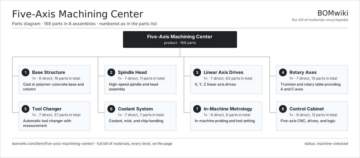
| # | Part | Qty | What it does |
|---|---|---|---|
| 1 | Base Structure 6 parts | 1× | Cast or polymer-concrete base and column |
| 2 | Spindle Head 7 parts | 1× | High-speed spindle and head assembly |
| 3 | Linear Axis Drives 7 parts | 1× | X, Y, Z linear axis drives |
| 4 | Rotary Axes 7 parts | 1× | Trunnion and rotary table providing A and C axes |
| 5 | Tool Changer 7 parts | 1× | Automatic tool changer with measurement |
| 6 | Coolant System 7 parts | 1× | Coolant, mist, and chip handling |
| 7 | In-Machine Metrology 6 parts | 1× | In-machine probing and tool setting |
| 8 | Control Cabinet 8 parts | 1× | Five-axis CNC, drives, and logic |
3D model
No 3D model yet. Have a CAD file of this? Add a 3D model — STL renders right on this page; STEP, FreeCAD, and OpenSCAD sources are welcome too (openly licensed, like all 3D models on BOMwiki).
Build & assembly graph
expand / collapse · shared sub-assemblies converge · links to related products · est. labourTap an assembly to expand/collapse · tap a part to open it · use “Open page” for any node · drag to pan, scroll to zoom.
Bill of materials for Five-Axis Machining Center
8 top-level lines · 67 rows shown · 168 parts total · indented to 3 levels| # | Item / sub-assembly | Part no. | Qty/assy | Ext. qty | Parts | Type |
|---|---|---|---|---|---|---|
| 1 | Base Structure 6 parts | fax-base-structure | 1× | 1 | 19 | assembly |
| 1.1 | Base Casting | fax-base-casting | 1× | 1 | · | part |
| 1.2 | Column | fax-column | 1× | 1 | · | part |
| 1.3 | Linear Rail | fax-linear-rail | 6× | 6 | · | part |
| 1.4 | Way Cover | fax-way-cover | 4× | 4 | · | part |
| 1.5 | Leveling Mount | fax-leveling-mount | 6× | 6 | · | part |
| 1.6 | Fastener Set | fastener-set | 1× | 1 | · | part |
| 2 | Spindle Head 7 parts | fax-spindle-head | 1× | 1 | 11 | assembly |
| 2.1 | Motorized Spindle | fax-motor-spindle | 1× | 1 | · | part |
| 2.2 | HSK Taper | fax-spindle-taper | 1× | 1 | · | part |
| 2.3 | Drawbar | fax-drawbar | 1× | 1 | · | part |
| 2.4 | Spindle Cooling Jacket | fax-spindle-cooling | 1× | 1 | · | part |
| 2.5 | Ball Bearing | ball-bearing | 4× | 4 | · | part |
| 2.6 | Oil Seal | oil-seal | 2× | 2 | · | part |
| 2.7 | Spindle Encoder | fax-spindle-encoder | 1× | 1 | · | part |
| 3 | Linear Axis Drives 7 parts | fax-linear-drives | 1× | 1 | 63 | assembly |
| 3.1 | Servo Motor 4 parts | servo-motor | 2× | 2 | 24 | assembly |
| 3.1.1 | Stator Assembly 3 parts + deeper › | stator-assembly | 1× | 2 | 3 | assembly |
| 3.1.2 | Rotor Assembly 4 parts + deeper › | rotor-assembly | 1× | 2 | 19 | assembly |
| 3.1.3 | Encoder | encoder | 1× | 2 | · | part |
| 3.1.4 | Motor Housing | motor-housing | 1× | 2 | · | part |
| 3.2 | Linear Motor | fax-linear-motor | 1× | 1 | · | part |
| 3.3 | Ball Screw | ball-screw | 2× | 2 | · | part |
| 3.4 | Linear Guide Rail | linear-guide | 6× | 6 | · | part |
| 3.5 | Linear Scale | fax-linear-scale | 3× | 3 | · | part |
| 3.6 | Bellows Coupling | fax-coupling | 2× | 2 | · | part |
| 3.7 | Lubrication Pump | fax-lube-pump | 1× | 1 | · | part |
| 4 | Rotary Axes 7 parts | fax-rotary-axes | 1× | 1 | 13 | assembly |
| 4.1 | Trunnion | fax-trunnion | 1× | 1 | · | part |
| 4.2 | Rotary Table | fax-rotary-table | 1× | 1 | · | part |
| 4.3 | Torque Motor | fax-torque-motor | 2× | 2 | · | part |
| 4.4 | Rotary Encoder | fax-rotary-encoder | 2× | 2 | · | part |
| 4.5 | Axis Brake | fax-axis-brake | 2× | 2 | · | part |
| 4.6 | Ball Bearing | ball-bearing | 4× | 4 | · | part |
| 4.7 | O-Ring Set | oring-set | 1× | 1 | · | part |
| 5 | Tool Changer 7 parts | fax-tool-changer | 1× | 1 | 37 | assembly |
| 5.1 | Tool Magazine | fax-tool-magazine | 1× | 1 | · | part |
| 5.2 | Tool Change Arm | fax-changer-arm | 1× | 1 | · | part |
| 5.3 | Tool Pocket | fax-tool-pocket | 30× | 30 | · | part |
| 5.4 | Laser Tool Setter | fax-laser-tool-setter | 1× | 1 | · | part |
| 5.5 | Magazine Motor | fax-magazine-motor | 1× | 1 | · | part |
| 5.6 | Helical Gear Pair | gear-pair | 1× | 1 | · | part |
| 5.7 | Relay | relay | 2× | 2 | · | part |
| 6 | Coolant System 7 parts | fax-coolant-system | 1× | 1 | 7 | assembly |
| 6.1 | Coolant Tank | fax-coolant-tank | 1× | 1 | · | part |
| 6.2 | Flood Pump | fax-flood-pump | 1× | 1 | · | part |
| 6.3 | Through-Spindle Pump | fax-tsc-pump | 1× | 1 | · | part |
| 6.4 | Air Blast Unit | fax-air-blast | 1× | 1 | · | part |
| 6.5 | Chip Conveyor | vmc-chip-conveyor | 1× | 1 | · | part |
| 6.6 | Coolant Filter | vmc-coolant-filter | 1× | 1 | · | part |
| 6.7 | O-Ring Set | oring-set | 1× | 1 | · | part |
| 7 | In-Machine Metrology 6 parts | fax-metrology | 1× | 1 | 6 | assembly |
| 7.1 | Touch Probe | fax-touch-probe | 1× | 1 | · | part |
| 7.2 | Probe Receiver | fax-probe-receiver | 1× | 1 | · | part |
| 7.3 | Calibration Sphere | fax-calibration-sphere | 1× | 1 | · | part |
| 7.4 | Tool Probe | fax-tool-probe | 1× | 1 | · | part |
| 7.5 | Bare PCB | pcb-bare | 1× | 1 | · | part |
| 7.6 | Connector | connector | 1× | 1 | · | part |
| 8 | Control Cabinet 8 parts | fax-control-cabinet | 1× | 1 | 12 | assembly |
| 8.1 | CNC Control | fax-cnc-control | 1× | 1 | · | part |
| 8.2 | Servo Amplifier | fax-servo-amp | 5× | 5 | · | part |
| 8.3 | Spindle Drive | fax-spindle-drive | 1× | 1 | · | part |
| 8.4 | Operator Panel | fax-operator-panel | 1× | 1 | · | part |
| 8.5 | Power Supply | power-supply | 1× | 1 | · | part |
| 8.6 | Machine PLC | fax-plc | 1× | 1 | · | part |
| 8.7 | LCD Panel | lcd-panel | 1× | 1 | · | part |
| 8.8 | Wire Bundle | wire-bundle | 1× | 1 | · | part |
Related products
same domain, ranked by shared parts Vertical Machining Center
195 parts · shares 8 with this page
Vertical Machining Center
195 parts · shares 8 with this page
 Bed-Type Milling Machine
151 parts · shares 7 with this page
Gantry Milling Machine
198 parts · shares 6 with this page
Bed-Type Milling Machine
151 parts · shares 7 with this page
Gantry Milling Machine
198 parts · shares 6 with this page
 Horizontal Machining Center
240 parts · shares 6 with this page
Bar Chamfering Machine
1,148 parts · shares 6 with this page
Horizontal Machining Center
240 parts · shares 6 with this page
Bar Chamfering Machine
1,148 parts · shares 6 with this page
 Bevel Gear Generator
201 parts · shares 6 with this page
Bevel Gear Generator
201 parts · shares 6 with this page
Sourcing: possible vendors
Prices, MOQ, and lead times are algorithmic estimates, not quotes, and not claims about these companies. Company mappings are curated by keyword; est. price band $10k–$1M. How estimates work| Vendor | HQ | Specialty | MOQ | Lead time |
|---|---|---|---|---|
|
🇩🇪DMG MORI
dmgmori.com ↗
|
Bielefeld, DE | Machine tools | 5 units | 12–20 wks |
|
🇯🇵Mazak
mazak.com ↗
|
Oguchi, JP | Machine tools | 5 units | 12–20 wks |
| haascnc.com ↗ | Oxnard, US | CNC machine tools | 5 units | 12–20 wks |
|
🇯🇵Okuma
okuma.com ↗
|
Niwa, JP | Machine tools | 5 units | 12–20 wks |
|
🇩🇪Trumpf
trumpf.com ↗
|
Ditzingen, DE | Laser & sheet-metal machines | 5 units | 12–20 wks |
925-word article