Double-Disc Grinder
ProductOverview
A double-disc grinder finishes both parallel faces of a part at the same time. The part passes through a narrow gap between two opposed abrasive discs, and each disc grinds the face it touches, so a single pass leaves both surfaces flat, smooth, and parallel to each other. Because the two Grinding Disc faces work against each other through the part, the cutting forces largely cancel: the work is not pushed hard to one side, and thin or delicate blanks can be ground that would distort in a single-side process. The machine is built for production thickness and parallelism work on washers, piston rings, gears, blades, connecting rods, vane pump rotors, and many other automotive and bearing components. Parallelism of a few microns and flatness of one to three microns are normal production figures.
How it works
The two spindles, the Left Wheel Spindle Assembly and the Right Wheel Spindle Assembly, are set facing each other with their abrasive faces a controlled distance apart. That gap is the finished thickness of the part. As a blank enters the gap, both discs cut at once, and the part leaves at the gap dimension regardless of how thick it was going in, within the stock the machine can remove in one pass. The Infeed Slide sets and closes that gap, advancing one spindle toward the other so the discs reach finished size, and on CNC machines it resolves to about 0.1 micron.
Parallelism comes from the relative attitude of the two discs. If the faces are not truly parallel, the part comes out as a wedge. The Spindle Tilt Mechanism cants one spindle by fractions of a degree, and the Parallelism Micro-Adjust trims residual taper, so the operator can dial both faces into the same plane and hold thickness variation across the part in the micron range. Disc surface speed runs 25-45 m/s, and each Disc Drive Motor holds that speed steady as the abrasive wears so the cut stays predictable.
Workfeed types
How parts get into the gap defines the machine. The most common arrangement is a rotary carrier: a slotted Rotary Carrier Plate holds parts in pockets and turns them slowly through the grinding zone so the whole face is swept evenly, driven by the Carrier Drive at 1-20 rev/min. Hardened Work Pocket Inserts locate each blank and take the side load. A second arrangement is throughfeed, where parts run continuously between the discs guided by Throughfeed Guides rails, used for high volumes of washers, rings, and discs. A third is oscillating or reciprocating feed, where a carrier moves the part back and forth across the disc faces to spread wear and improve flatness on larger workpieces. In every mode the Part Loader and Ejector presents blanks and clears finished parts so the cycle runs unattended.
Discs, dressing, and size control
Both discs are consumable and both are trued by diamond. The discs come solid or segmented; segmented discs leave gaps between abrasive blocks that let coolant reach the cut and let chips escape, which keeps the grind cooler and is preferred for heavier stock removal. The Left Disc Dresser and Right Disc Dresser each draw a Dressing Diamond across their disc to restore a flat cutting face and expose sharp grain. Both faces must be dressed to the same plane, since a difference between them prints straight into part taper. Every dress removes disc material, so the CNC Control compensates the infeed automatically. Production cells close the loop with the In-Process Thickness Gauging system: a Thickness Gauge Head straddles the part and reads thickness during the cut, and the control retracts the infeed at finished size whatever the disc wear.
Structure and thermal control
Grinding flat faces in opposition is sensitive to vibration and to heat. The Machine Base is grey iron or polymer concrete at 2-15 t for its damping, and each Spindle Column holds its spindle in rigid opposition to the other. The spindles run on Spindle Shaft assemblies whose stiffness bounds the flatness the machine can reach. Heat is the size killer in any precision grinder, so the Coolant System system floods both contacts through Coolant Nozzles aimed into the disc-work zone and into the segment gaps, the Filter Unit strips swarf and grit that would scratch the finish, and a Coolant Chiller holds coolant within about a degree so the machine does not grow during a shift.
Production context
Double-disc grinding is a volume process used where flatness, parallelism, and thickness must be held tightly across many identical parts. Removing stock from both faces at once roughly halves cycle time against single-side grinding and keeps the part balanced in the cut, which is why it dominates finishing of washers, friction plates, piston rings, vane pump components, and similar flat parts. Setup is the skilled part of the work: gap, disc tilt, carrier speed, and dressing geometry all interact, and they are adjusted iteratively until the first parts gauge in tolerance. Once set, the machine runs through automated loading at high rate, so the economics favor long runs of one part over frequent changeovers.
Double-Disc Grinder parts and their functions
9 top-level parts · 153 parts in total · full bill of materials below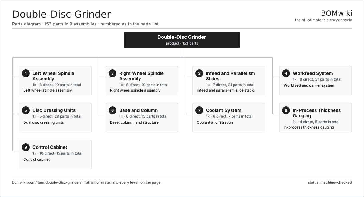
| # | Part | Qty | What it does |
|---|---|---|---|
| 1 | Left Wheel Spindle Assembly 8 parts | 1× | Left wheel spindle assembly |
| 2 | Right Wheel Spindle Assembly 8 parts | 1× | Right wheel spindle assembly |
| 3 | Infeed and Parallelism Slides 7 parts | 1× | Infeed and parallelism slide stack |
| 4 | Workfeed System 8 parts | 1× | Workfeed and carrier system |
| 5 | Disc Dressing Units 5 parts | 1× | Dual disc dressing units |
| 6 | Base and Column 6 parts | 1× | Base, column, and structure |
| 7 | Coolant System 6 parts | 1× | Coolant and filtration |
| 8 | In-Process Thickness Gauging 4 parts | 1× | In-process thickness gauging |
| 9 | Control Cabinet 10 parts | 1× | Control cabinet |
3D model
No 3D model yet. Have a CAD file of this? Add a 3D model — STL renders right on this page; STEP, FreeCAD, and OpenSCAD sources are welcome too (openly licensed, like all 3D models on BOMwiki).
Build & assembly graph
expand / collapse · shared sub-assemblies converge · links to related products · est. labourTap an assembly to expand/collapse · tap a part to open it · use “Open page” for any node · drag to pan, scroll to zoom.
Bill of materials for Double-Disc Grinder
9 top-level lines · 83 rows shown · 153 parts total · indented to 3 levels| # | Item / sub-assembly | Part no. | Qty/assy | Ext. qty | Parts | Type |
|---|---|---|---|---|---|---|
| 1 | Left Wheel Spindle Assembly 8 parts | double-disc-grinder-left-spindle | 1× | 1 | 10 | assembly |
| 1.1 | Grinding Disc | double-disc-grinder-grinding-disc | 1× | 1 | · | part |
| 1.2 | Spindle Shaft | double-disc-grinder-spindle-shaft | 1× | 1 | · | part |
| 1.3 | Spindle Housing | double-disc-grinder-spindle-housing | 1× | 1 | · | part |
| 1.4 | Disc Drive Motor | double-disc-grinder-disc-motor | 1× | 1 | · | part |
| 1.5 | Disc Mounting Hub | double-disc-grinder-disc-hub | 1× | 1 | · | part |
| 1.6 | Ball Bearing | ball-bearing | 2× | 2 | · | part |
| 1.7 | Oil Seal | oil-seal | 2× | 2 | · | part |
| 1.8 | Drive Belt | drive-belt | 1× | 1 | · | part |
| 2 | Right Wheel Spindle Assembly 8 parts | double-disc-grinder-right-spindle | 1× | 1 | 10 | assembly |
| 2.1 | Grinding Disc | double-disc-grinder-grinding-disc | 1× | 1 | · | part |
| 2.2 | Spindle Shaft | double-disc-grinder-spindle-shaft | 1× | 1 | · | part |
| 2.3 | Spindle Housing | double-disc-grinder-spindle-housing | 1× | 1 | · | part |
| 2.4 | Disc Drive Motor | double-disc-grinder-disc-motor | 1× | 1 | · | part |
| 2.5 | Disc Mounting Hub | double-disc-grinder-disc-hub | 1× | 1 | · | part |
| 2.6 | Ball Bearing | ball-bearing | 2× | 2 | · | part |
| 2.7 | Oil Seal | oil-seal | 2× | 2 | · | part |
| 2.8 | Drive Belt | drive-belt | 1× | 1 | · | part |
| 3 | Infeed and Parallelism Slides 7 parts | double-disc-grinder-parallelism-slides | 1× | 1 | 31 | assembly |
| 3.1 | Infeed Slide | double-disc-grinder-infeed-slide | 1× | 1 | · | part |
| 3.2 | Spindle Tilt Mechanism | double-disc-grinder-tilt-mechanism | 1× | 1 | · | part |
| 3.3 | Parallelism Micro-Adjust | double-disc-grinder-parallelism-adjust | 1× | 1 | · | part |
| 3.4 | Ball Screw | ball-screw | 1× | 1 | · | part |
| 3.5 | Linear Guide Rail | linear-guide | 2× | 2 | · | part |
| 3.6 | Servo Motor 4 parts | servo-motor | 1× | 1 | 24 | assembly |
| 3.6.1 | Stator Assembly 3 parts + deeper › | stator-assembly | 1× | 1 | 3 | assembly |
| 3.6.2 | Rotor Assembly 4 parts + deeper › | rotor-assembly | 1× | 1 | 19 | assembly |
| 3.6.3 | Encoder | encoder | 1× | 1 | · | part |
| 3.6.4 | Motor Housing | motor-housing | 1× | 1 | · | part |
| 3.7 | Encoder | encoder | 1× | 1 | · | part |
| 4 | Workfeed System 8 parts | double-disc-grinder-workfeed | 1× | 1 | 31 | assembly |
| 4.1 | Rotary Carrier Plate | double-disc-grinder-carrier-plate | 1× | 1 | · | part |
| 4.2 | Carrier Drive | double-disc-grinder-carrier-drive | 1× | 1 | · | part |
| 4.3 | Work Pocket Inserts | double-disc-grinder-work-pockets | 1× | 1 | · | part |
| 4.4 | Throughfeed Guides | double-disc-grinder-throughfeed-guide | 1× | 1 | · | part |
| 4.5 | Part Loader and Ejector | double-disc-grinder-loader | 1× | 1 | · | part |
| 4.6 | Gearbox Housing | gearbox-housing | 1× | 1 | · | part |
| 4.7 | Helical Gear Pair | gear-pair | 1× | 1 | · | part |
| 4.8 | Servo Motor 4 parts | servo-motor | 1× | 1 | 24 | assembly |
| 4.8.1 | Stator Assembly 3 parts + deeper › | stator-assembly | 1× | 1 | 3 | assembly |
| 4.8.2 | Rotor Assembly 4 parts + deeper › | rotor-assembly | 1× | 1 | 19 | assembly |
| 4.8.3 | Encoder | encoder | 1× | 1 | · | part |
| 4.8.4 | Motor Housing | motor-housing | 1× | 1 | · | part |
| 5 | Disc Dressing Units 5 parts | double-disc-grinder-dressers | 1× | 1 | 29 | assembly |
| 5.1 | Left Disc Dresser | double-disc-grinder-left-dresser | 1× | 1 | · | part |
| 5.2 | Right Disc Dresser | double-disc-grinder-right-dresser | 1× | 1 | · | part |
| 5.3 | Dressing Diamond | double-disc-grinder-dress-diamond | 2× | 2 | · | part |
| 5.4 | Dresser Traverse Slide | double-disc-grinder-dress-slide | 1× | 1 | · | part |
| 5.5 | Servo Motor 4 parts | servo-motor | 1× | 1 | 24 | assembly |
| 5.5.1 | Stator Assembly 3 parts + deeper › | stator-assembly | 1× | 1 | 3 | assembly |
| 5.5.2 | Rotor Assembly 4 parts + deeper › | rotor-assembly | 1× | 1 | 19 | assembly |
| 5.5.3 | Encoder | encoder | 1× | 1 | · | part |
| 5.5.4 | Motor Housing | motor-housing | 1× | 1 | · | part |
| 6 | Base and Column 6 parts | double-disc-grinder-base | 1× | 1 | 15 | assembly |
| 6.1 | Machine Base | double-disc-grinder-bed | 1× | 1 | · | part |
| 6.2 | Spindle Column | double-disc-grinder-column | 2× | 2 | · | part |
| 6.3 | Leveling Mount | double-disc-grinder-leveling | 6× | 6 | · | part |
| 6.4 | Machine Enclosure | double-disc-grinder-enclosure | 1× | 1 | · | part |
| 6.5 | Sheet Metal Panel | sheet-panel | 4× | 4 | · | part |
| 6.6 | Fastener Set | fastener-set | 1× | 1 | · | part |
| 7 | Coolant System 6 parts | double-disc-grinder-coolant | 1× | 1 | 7 | assembly |
| 7.1 | Coolant Pump | coolant-pump | 1× | 1 | · | part |
| 7.2 | Coolant Tank | double-disc-grinder-coolant-tank | 1× | 1 | · | part |
| 7.3 | Filter Unit | double-disc-grinder-filter-unit | 1× | 1 | · | part |
| 7.4 | Coolant Nozzles | double-disc-grinder-coolant-nozzles | 2× | 2 | · | part |
| 7.5 | Coolant Chiller | double-disc-grinder-chiller | 1× | 1 | · | part |
| 7.6 | Pressure Sensor | pressure-sensor | 1× | 1 | · | part |
| 8 | In-Process Thickness Gauging 4 parts | double-disc-grinder-gauging | 1× | 1 | 5 | assembly |
| 8.1 | Thickness Gauge Head | double-disc-grinder-thickness-gauge | 1× | 1 | · | part |
| 8.2 | Gauge Amplifier | double-disc-grinder-gauge-amplifier | 1× | 1 | · | part |
| 8.3 | Pressure Sensor | pressure-sensor | 1× | 1 | · | part |
| 8.4 | Connector | connector | 2× | 2 | · | part |
| 9 | Control Cabinet 10 parts | double-disc-grinder-controls | 1× | 1 | 15 | assembly |
| 9.1 | CNC Control | double-disc-grinder-cnc | 1× | 1 | · | part |
| 9.2 | Operator HMI | double-disc-grinder-hmi | 1× | 1 | · | part |
| 9.3 | Power Supply | power-supply | 1× | 1 | · | part |
| 9.4 | IGBT Power Module | igbt-module | 3× | 3 | · | part |
| 9.5 | Bare PCB | pcb-bare | 1× | 1 | · | part |
| 9.6 | Microcontroller | mcu | 1× | 1 | · | part |
| 9.7 | SMD Passive (R/C/L) | smd-passives | 1× | 1 | · | part |
| 9.8 | Relay | relay | 4× | 4 | · | part |
| 9.9 | Wire Bundle | wire-bundle | 1× | 1 | · | part |
| 9.10 | LCD Panel | lcd-panel | 1× | 1 | · | part |
Related products
same domain, ranked by shared parts Rotary-Table Surface Grinder
172 parts · shares 10 with this page
Spline Rolling Machine
138 parts · shares 9 with this page
Rotary-Table Surface Grinder
172 parts · shares 10 with this page
Spline Rolling Machine
138 parts · shares 9 with this page
 Bevel Gear Generator
201 parts · shares 9 with this page
Bevel Gear Generator
201 parts · shares 9 with this page
 Radial Forging Machine
288 parts · shares 9 with this page
Universal Cylindrical Grinder
153 parts · shares 8 with this page
Radial Forging Machine
288 parts · shares 9 with this page
Universal Cylindrical Grinder
153 parts · shares 8 with this page
 Centerless Grinder
129 parts · shares 7 with this page
Centerless Grinder
129 parts · shares 7 with this page
Sourcing: possible vendors
Prices, MOQ, and lead times are algorithmic estimates, not quotes, and not claims about these companies. Company mappings are curated by keyword; est. price band $10k–$1M. How estimates work| Vendor | HQ | Specialty | MOQ | Lead time |
|---|---|---|---|---|
|
🇩🇪DMG MORI
dmgmori.com ↗
|
Bielefeld, DE | Machine tools | 5 units | 12–20 wks |
|
🇯🇵Mazak
mazak.com ↗
|
Oguchi, JP | Machine tools | 5 units | 12–20 wks |
| haascnc.com ↗ | Oxnard, US | CNC machine tools | 5 units | 12–20 wks |
|
🇯🇵Okuma
okuma.com ↗
|
Niwa, JP | Machine tools | 5 units | 12–20 wks |
|
🇩🇪Trumpf
trumpf.com ↗
|
Ditzingen, DE | Laser & sheet-metal machines | 5 units | 12–20 wks |
914-word article