Rotary Draw Bender
ProductOverview
A rotary draw bender forms a precise bend in tube or pipe by drawing the stock around a fixed-radius die while a clamp die holds the tube and a pressure die supports it against the bend. The method is the standard for parts where bend radius, angle and wall integrity all matter: roll cages, exhaust systems, handrails, hydraulic lines, furniture frames and aircraft tubing. Unlike compression or ram bending, the draw method keeps the bend radius constant and predictable because the tube wraps a dedicated bend die rather than being pushed across a former.
The CNC version coordinates three axes. The C axis rotates the bend arm through the programmed angle, the Y axis feeds the tube to set the straight length between bends, and the B axis rotates the tube to place each bend in the correct plane. A finished part with several bends in different planes comes off the machine in one cycle without the operator repositioning the stock by hand.
How It Works
The tube is loaded through the Collet Chuck on the Carriage (Y/B Axes) and pushed forward until the bend point reaches the Bend Die (Radius Block). The Clamp Die Cylinder closes the Clamp Die against the tube, pinning it to the bend die. The Pressure Die presses the trailing straight section into the die groove and holds pressure through the bend.
The C-Axis Drive then rotates the Bend Arm around the Main Slewing Bearing. As the arm turns, the clamped tube is drawn around the bend die, taking the die radius as its own centerline radius. The Bend Angle Encoder reads the arm position so the control stops exactly at the target angle. After the bend the clamp opens, the pressure die retracts, and the Y-Axis (Feed) feeds more tube while the B-Axis (Rotation) indexes the rotation for the next bend.
Tooling
The bend quality depends almost entirely on the Bend Tooling Set stack. Each combination of tube diameter, wall and bend radius needs a matched set. The bend die carries the radius groove. The clamp die grips against it with enough length to prevent slip during draw. The pressure die is a long straight die that follows the tube and can be set to move forward with the draw, which reduces wall thinning on the outer radius.
For tight radii and thin walls, the inner radius wants to wrinkle. The Wiper Die sits just behind the bend tangent with a feathered tip reaching into the die groove, ironing out wrinkles before they form. Wiper dies are consumable; the feather tip wears and is re-ground or replaced. Tooling is hardened tool steel for steel tube and is often bronze or aluminum-bronze where galling on stainless or titanium is a concern.
Mandrel Support
Thin-wall tube collapses or flattens on the bend without internal support. The Mandrel System inserts a Mandrel (Ball Type) on the end of the Mandrel Rod so the ball links sit right at the bend tangent and hold the bore round as the tube is drawn over them. Ball-link mandrels flex through the bend and are pulled back by the Mandrel Extractor Cylinder once the bend is complete. The Mandrel Lubricator meters lubricant onto the mandrel so it slides inside the tube without scoring the bore. Mandrel setup, how far the ball sits past the tangent line, is the most sensitive adjustment on the machine and decides whether a thin-wall bend comes out smooth or wrinkled.
Hydraulic and Drive System
The Hydraulic Power Unit supplies the clamp, pressure die and mandrel cylinders. A gear Hydraulic Pump driven by the Pump Motor feeds the Valve Block, which routes oil to each cylinder through solenoid directional valves. A Pressure Sensor on the clamp line confirms grip before the bend starts, since a tube that slips during draw ruins the part and can damage tooling. System pressure runs around 160 bar, capped by the relief valve.
The three motion axes use brushless Servo Motor drives. The C axis turns through a Helical Gearbox and a final Helical Gear Pair to deliver the high torque a large-diameter bend needs at low arm speed. The Y axis uses a Ball Screw on Linear Guide Rail rails for accurate feed length, and the B axis uses a gear set for tube rotation. Each axis is closed-loop, giving the ±0.1 degree repeatability the part programs rely on.
Control and Programming
The CNC Control runs the bend program from a part defined as a list of feed lengths, rotation angles and bend angles. The operator enters these at the Touchscreen HMI, or the program is generated from CAD tube geometry offline. The CNC Control Board interpolates the three axes and commands the Servo Driver units. The control also applies springback compensation: every material springs back a few degrees after the clamp opens, so the program overbends by a learned amount to land on the nominal angle. Most controls store springback values per material and tooling set so the first part of a run is in tolerance.
Materials and Variants
Frames and the Bed Weldment are welded steel, stress-relieved to keep the geometry stable under repeated bend reaction loads. Tooling is hardened steel or wear-resistant bronze depending on the tube material. Machines range from small benchtop benders for handrail and furniture stock up to large units bending 150 mm structural pipe for shipyards and construction. Right-hand and left-hand bend heads exist, and some machines carry multiple tooling stacks on a turret so they can switch radii within one part. The common thread across all sizes is the draw method itself: a fixed bend die, a clamp, a pressure die and, for thin wall, a mandrel and wiper.
Use and Maintenance
Daily work centers on tooling: clean and lubricate dies, check the wiper tip for wear, and confirm mandrel position after any tube change. The hydraulic oil and Return Filter are serviced on hours, and the slewing Main Slewing Bearing is greased on schedule. The Safety System system, light curtain and guarding, is interlocked so the bend arm cannot move with the work zone breached. Well-maintained, these machines hold tube parts to tight angular and length tolerances across long production runs.
Rotary Draw Bender parts and their functions
9 top-level parts · 821 parts in total · full bill of materials below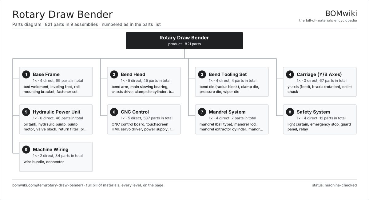
| # | Part | Qty | What it does |
|---|---|---|---|
| 1 | Base Frame 4 parts | 1× | Welded steel bed carrying the bend head, carriage rails and power unit. |
| 2 | Bend Head 5 parts | 1× | Rotating drive that turns the bend die through the programmed angle. |
| 3 | Bend Tooling Set 4 parts | 1× | Die stack that forms the bend radius and supports the tube wall. |
| 4 | Carriage (Y/B Axes) 3 parts | 1× | Servo carriage feeding tube length and rotating it between bends. |
| 5 | Hydraulic Power Unit 6 parts | 1× | Tank, pump and valves driving the clamp, pressure die and mandrel cylinders. |
| 6 | CNC Control 5 parts | 1× | Compute, drives and operator panel running the bend program. |
| 7 | Mandrel System 4 parts | 1× | Internal mandrel and rod supporting thin-wall tube through the bend. |
| 8 | Safety System 4 parts | 1× | Guarding, light curtain and e-stops halting motion on intrusion. |
| 9 | Machine Wiring 2 parts | 1× | Harnesses and connectors linking drives, valves and sensors. |
3D model
No 3D model yet. Have a CAD file of this? Add a 3D model — STL renders right on this page; STEP, FreeCAD, and OpenSCAD sources are welcome too (openly licensed, like all 3D models on BOMwiki).
Build & assembly graph
expand / collapse · shared sub-assemblies converge · links to related products · est. labourTap an assembly to expand/collapse · tap a part to open it · use “Open page” for any node · drag to pan, scroll to zoom.
Bill of materials for Rotary Draw Bender
9 top-level lines · 84 rows shown · 821 parts total · indented to 3 levels| # | Item / sub-assembly | Part no. | Qty/assy | Ext. qty | Parts | Type |
|---|---|---|---|---|---|---|
| 1 | Base Frame 4 parts | rotary-draw-bender-base-frame | 1× | 1 | 69 | assembly |
| 1.1 | Bed Weldment | rotary-draw-bender-bed-weldment | 1× | 1 | · | part |
| 1.2 | Leveling Foot | rotary-draw-bender-leveling-foot | 6× | 6 | · | part |
| 1.3 | Rail Mounting Bracket | rotary-draw-bender-rail-mount | 2× | 2 | · | part |
| 1.4 | Fastener Set | fastener-set | 60× | 60 | · | part |
| 2 | Bend Head 5 parts | rotary-draw-bender-bend-head | 1× | 1 | 45 | assembly |
| 2.1 | Bend Arm | rotary-draw-bender-bend-arm | 1× | 1 | · | part |
| 2.2 | Main Slewing Bearing | rotary-draw-bender-main-bearing | 1× | 1 | · | part |
| 2.3 | C-Axis Drive 4 parts | rotary-draw-bender-c-axis-drive | 1× | 1 | 36 | assembly |
| 2.3.1 | Servo Motor 4 parts + deeper › | servo-motor | 1× | 1 | 24 | assembly |
| 2.3.2 | Helical Gearbox 4 parts + deeper › | gearbox | 1× | 1 | 9 | assembly |
| 2.3.3 | Helical Gear Pair | gear-pair | 1× | 1 | · | part |
| 2.3.4 | Ball Bearing | ball-bearing | 2× | 2 | · | part |
| 2.4 | Clamp Die Cylinder 3 parts | rotary-draw-bender-clamp-cylinder | 1× | 1 | 6 | assembly |
| 2.4.1 | Cylinder Body | rotary-draw-bender-cyl-body | 1× | 1 | · | part |
| 2.4.2 | Oil Seal | oil-seal | 2× | 2 | · | part |
| 2.4.3 | O-Ring Set | oring-set | 3× | 3 | · | part |
| 2.5 | Bend Angle Encoder | rotary-draw-bender-angle-encoder | 1× | 1 | · | part |
| 3 | Bend Tooling Set 4 parts | rotary-draw-bender-tooling | 1× | 1 | 4 | assembly |
| 3.1 | Bend Die (Radius Block) | rotary-draw-bender-bend-die | 1× | 1 | · | part |
| 3.2 | Clamp Die | rotary-draw-bender-clamp-die | 1× | 1 | · | part |
| 3.3 | Pressure Die | rotary-draw-bender-pressure-die | 1× | 1 | · | part |
| 3.4 | Wiper Die | rotary-draw-bender-wiper-die | 1× | 1 | · | part |
| 4 | Carriage (Y/B Axes) 3 parts | rotary-draw-bender-carriage | 1× | 1 | 67 | assembly |
| 4.1 | Y-Axis (Feed) 4 parts | rotary-draw-bender-y-axis | 1× | 1 | 29 | assembly |
| 4.1.1 | Servo Motor 4 parts + deeper › | servo-motor | 1× | 1 | 24 | assembly |
| 4.1.2 | Ball Screw | ball-screw | 1× | 1 | · | part |
| 4.1.3 | Linear Guide Rail | linear-guide | 2× | 2 | · | part |
| 4.1.4 | Ball Bearing | ball-bearing | 2× | 2 | · | part |
| 4.2 | B-Axis (Rotation) 3 parts | rotary-draw-bender-b-axis | 1× | 1 | 27 | assembly |
| 4.2.1 | Servo Motor 4 parts + deeper › | servo-motor | 1× | 1 | 24 | assembly |
| 4.2.2 | Helical Gear Pair | gear-pair | 1× | 1 | · | part |
| 4.2.3 | Ball Bearing | ball-bearing | 2× | 2 | · | part |
| 4.3 | Collet Chuck 3 parts | rotary-draw-bender-collet | 1× | 1 | 11 | assembly |
| 4.3.1 | Collet Sleeve | rotary-draw-bender-collet-sleeve | 1× | 1 | · | part |
| 4.3.2 | Coil Spring | coil-spring | 2× | 2 | · | part |
| 4.3.3 | Fastener Set | fastener-set | 8× | 8 | · | part |
| 5 | Hydraulic Power Unit 6 parts | rotary-draw-bender-hydraulic-unit | 1× | 1 | 46 | assembly |
| 5.1 | Oil Tank | rotary-draw-bender-tank | 1× | 1 | · | part |
| 5.2 | Hydraulic Pump 3 parts | rotary-draw-bender-pump | 1× | 1 | 5 | assembly |
| 5.2.1 | Ball Bearing | ball-bearing | 2× | 2 | · | part |
| 5.2.2 | Oil Seal | oil-seal | 1× | 1 | · | part |
| 5.2.3 | O-Ring Set | oring-set | 2× | 2 | · | part |
| 5.3 | Pump Motor 3 parts | rotary-draw-bender-pump-motor | 1× | 1 | 24 | assembly |
| 5.3.1 | Stator Assembly 3 parts + deeper › | stator-assembly | 1× | 1 | 3 | assembly |
| 5.3.2 | Rotor Assembly 4 parts + deeper › | rotor-assembly | 1× | 1 | 19 | assembly |
| 5.3.3 | Ball Bearing | ball-bearing | 2× | 2 | · | part |
| 5.4 | Valve Block 3 parts | rotary-draw-bender-valve-block | 1× | 1 | 13 | assembly |
| 5.4.1 | Directional Valve | rotary-draw-bender-dir-valve | 4× | 4 | · | part |
| 5.4.2 | Relief Valve | rotary-draw-bender-relief-valve | 1× | 1 | · | part |
| 5.4.3 | O-Ring Set | oring-set | 8× | 8 | · | part |
| 5.5 | Return Filter | rotary-draw-bender-filter | 1× | 1 | · | part |
| 5.6 | Pressure Sensor | pressure-sensor | 2× | 2 | · | part |
| 6 | CNC Control 5 parts | rotary-draw-bender-cnc | 1× | 1 | 537 | assembly |
| 6.1 | CNC Control Board 3 parts | rotary-draw-bender-control-board | 1× | 1 | 223 | assembly |
| 6.1.1 | Bare PCB | pcb-bare | 1× | 1 | · | part |
| 6.1.2 | Microcontroller | mcu | 2× | 2 | · | part |
| 6.1.3 | SMD Passive (R/C/L) | smd-passives | 220× | 220 | · | part |
| 6.2 | Touchscreen HMI 3 parts | rotary-draw-bender-touchscreen | 1× | 1 | 62 | assembly |
| 6.2.1 | LCD Panel | lcd-panel | 1× | 1 | · | part |
| 6.2.2 | Bare PCB | pcb-bare | 1× | 1 | · | part |
| 6.2.3 | SMD Passive (R/C/L) | smd-passives | 60× | 60 | · | part |
| 6.3 | Servo Driver 2 parts | rotary-draw-bender-servo-driver | 3× | 3 | 81 | assembly |
| 6.3.1 | Bare PCB | pcb-bare | 1× | 3 | · | part |
| 6.3.2 | SMD Passive (R/C/L) | smd-passives | 80× | 240 | · | part |
| 6.4 | Power Supply | power-supply | 1× | 1 | · | part |
| 6.5 | Relay | relay | 8× | 8 | · | part |
| 7 | Mandrel System 4 parts | rotary-draw-bender-mandrel-system | 1× | 1 | 7 | assembly |
| 7.1 | Mandrel (Ball Type) | rotary-draw-bender-mandrel | 1× | 1 | · | part |
| 7.2 | Mandrel Rod | rotary-draw-bender-mandrel-rod | 1× | 1 | · | part |
| 7.3 | Mandrel Extractor Cylinder 2 parts | rotary-draw-bender-mandrel-cylinder | 1× | 1 | 4 | assembly |
| 7.3.1 | Oil Seal | oil-seal | 2× | 2 | · | part |
| 7.3.2 | O-Ring Set | oring-set | 2× | 2 | · | part |
| 7.4 | Mandrel Lubricator | rotary-draw-bender-mandrel-lube | 1× | 1 | · | part |
| 8 | Safety System 4 parts | rotary-draw-bender-safety | 1× | 1 | 12 | assembly |
| 8.1 | Light Curtain 2 parts | rotary-draw-bender-light-curtain | 1× | 1 | 4 | assembly |
| 8.1.1 | Bare PCB | pcb-bare | 2× | 2 | · | part |
| 8.1.2 | Connector | connector | 2× | 2 | · | part |
| 8.2 | Emergency Stop | rotary-draw-bender-estop | 2× | 2 | · | part |
| 8.3 | Guard Panel | rotary-draw-bender-guard-panel | 4× | 4 | · | part |
| 8.4 | Relay | relay | 2× | 2 | · | part |
| 9 | Machine Wiring 2 parts | rotary-draw-bender-wiring | 1× | 1 | 34 | assembly |
| 9.1 | Wire Bundle | wire-bundle | 4× | 4 | · | part |
| 9.2 | Connector | connector | 30× | 30 | · | part |
Related products
same domain, ranked by shared parts Shaft Straightening Press
93 parts · shares 5 with this page
Shaft Straightening Press
93 parts · shares 5 with this page
 Flat-Die Thread Roller
65 parts · shares 4 with this page
Flat-Die Thread Roller
65 parts · shares 4 with this page
Sourcing: possible vendors
Prices, MOQ, and lead times are algorithmic estimates, not quotes, and not claims about these companies. Company mappings are curated by keyword; est. price band $10k–$1M. How estimates work| Vendor | HQ | Specialty | MOQ | Lead time |
|---|---|---|---|---|
|
🇩🇪DMG MORI
dmgmori.com ↗
|
Bielefeld, DE | Machine tools | 5 units | 12–20 wks |
|
🇯🇵Mazak
mazak.com ↗
|
Oguchi, JP | Machine tools | 5 units | 12–20 wks |
| haascnc.com ↗ | Oxnard, US | CNC machine tools | 5 units | 12–20 wks |
|
🇯🇵Okuma
okuma.com ↗
|
Niwa, JP | Machine tools | 5 units | 12–20 wks |
|
🇩🇪Trumpf
trumpf.com ↗
|
Ditzingen, DE | Laser & sheet-metal machines | 5 units | 12–20 wks |
1,114-word article