Hydraulic Guillotine Shear
ProductOverview
A hydraulic guillotine shear cuts straight lines through sheet and plate metal by driving a long upper blade down past a fixed lower blade. The machine is built around a welded steel frame that resists the cutting reaction, two ram cylinders that power the beam, and a blade set that does the cutting. The hydraulic power unit supplies oil to the cylinders, while the NC control system coordinates stroke length, blade gap, rake angle, and the position of the back gauge.
This class of machine is the workhorse of any sheet-metal shop. A swing-beam guillotine pivots the upper beam about a rear axis so the blade sweeps through an arc, which keeps the blade gap consistent across the cut. The variable rake feature tilts the beam so only a short length of metal is in contact at any instant, lowering the peak force needed and reducing twist in narrow strips. The rated capacity quoted on the nameplate, 6 mm of mild steel across the full 3,050 mm length, assumes a tensile strength near 450 MPa; cutting harder or thicker stock reduces the usable width.
Frame and beam
The frame is a stress-relieved weldment of two side housing plates tied together by the worktable bed and a rear tie beam. The swing ram beam rides in guide gibs and pivots on bronze pivot bushings at the rear. During a cut the side housings see several hundred kilonewtons of spreading load, so the plates are thick S355 steel and the whole frame is annealed after welding to remove residual stress that would otherwise let the blade gap drift over time. The worktable carries a ball transfer table of ball transfer units so an operator can slide a heavy blank into position with little effort.
Hydraulic drive
Two ram cylinders, one at each end of the beam, push the beam down through the work and retract it after the cut. Each cylinder has a honed tube, a hard-chrome rod, and a seal kit of rod wipers and piston seals. Oil comes from the power unit: an axial piston pump driven by an 11 kW electric motor draws from the oil tank and feeds the valve manifold. A proportional valve meters flow to set stroke speed and length, a relief valve caps system pressure at 250 bar, and directional valves switch between the down and return strokes. A bladder accumulator stores energy for a fast return, and an oil cooler holds the tank temperature down during continuous production. A pressure sensor feeds system pressure back to the control so the machine can sense an overload before the relief valve has to dump.
Blades, gap, and rake
Cutting quality depends almost entirely on the blade set. The upper blade bolts to the beam and the lower blade bolts to the table through blade seat blocks, both held by clamping bolts. Each blade is a four-edge tool-steel section, so a worn edge can be rotated three times before regrinding. The blade gap adjuster uses eccentric bushings turned by a handwheel to set clearance between the blades, typically two to ten percent of stock thickness; too tight a gap wears the edges, too wide a gap leaves a burr and a rolled edge. The rake angle adjuster uses a small rake cylinder and linkage to tilt the beam between 0.5 and 2.5 degrees, trading cut speed against the bow that rake puts into long narrow cutoffs.
Hold-down and material support
Before the blade touches the work, the hold-down system clamps it flat. Eight hold-down cylinders press hardened pressure feet onto the sheet just behind the cut line, sequenced ahead of the ram by the sequence valve; return springs lift the feet clear when pressure releases. Clamping stops the sheet from lifting and twisting as the blade enters, which is what keeps the cut edge square. At the front, two support arms and a squaring arm with a graduated scale carry and reference the workpiece.
Back gauge and control
For repeat cuts to a set width, the back gauge positions a stop bar behind the blades. A servo motor drives a ball screw through a reduction gear, the gauge rides on linear guides, and a gauge encoder closes the position loop to about ±0.10 mm over a 1,000 mm range. Finger stops let the operator register a sheet edge by hand. The NC control ties it together: a control board runs the cut sequence, a touchscreen shows the program and lets the operator enter length and quantity, a servo driver moves the gauge, and a 24 V power supply feeds the output relays and the foot pedal.
Safety and wiring
Because the blade line is an obvious hazard, the safety system is mandatory. A slotted front finger guard limits hand access, a light curtain stops the stroke if anything breaks the beam, a rear guard covers the back gauge travel, and three emergency stops feed a dual-channel safety relay. All of it connects through the machine wiring: a wire bundle, connectors, drag chains for the moving axes, and terminal blocks in the cabinet. Routine maintenance is mostly hydraulic: checking oil level and filter condition, regrinding or rotating blades, and resetting the blade gap as the edges wear.
Hydraulic Guillotine Shear parts and their functions
10 top-level parts · 600 parts in total · full bill of materials below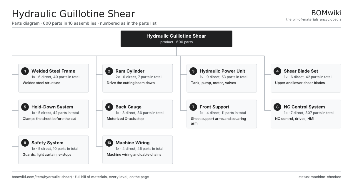
| # | Part | Qty | What it does |
|---|---|---|---|
| 1 | Welded Steel Frame 6 parts | 1× | Welded steel structure |
| 2 | Ram Cylinder 6 parts | 2× | Drive the cutting beam down |
| 3 | Hydraulic Power Unit 9 parts | 1× | Tank, pump, motor, valves |
| 4 | Shear Blade Set 6 parts | 1× | Upper and lower shear blades |
| 5 | Hold-Down System 5 parts | 1× | Clamps the sheet before the cut |
| 6 | Back Gauge 8 parts | 1× | Motorized X-axis stop |
| 7 | Front Support 4 parts | 1× | Sheet support arms and squaring arm |
| 8 | NC Control System 7 parts | 1× | NC control, drives, HMI |
| 9 | Safety System 5 parts | 1× | Guards, light curtain, e-stops |
| 10 | Machine Wiring 4 parts | 1× | Machine wiring and cable chains |
3D model
No 3D model yet. Have a CAD file of this? Add a 3D model — STL renders right on this page; STEP, FreeCAD, and OpenSCAD sources are welcome too (openly licensed, like all 3D models on BOMwiki).
Build & assembly graph
expand / collapse · shared sub-assemblies converge · links to related products · est. labourTap an assembly to expand/collapse · tap a part to open it · use “Open page” for any node · drag to pan, scroll to zoom.
Bill of materials for Hydraulic Guillotine Shear
10 top-level lines · 132 rows shown · 600 parts total · indented to 3 levels| # | Item / sub-assembly | Part no. | Qty/assy | Ext. qty | Parts | Type |
|---|---|---|---|---|---|---|
| 1 | Welded Steel Frame 6 parts | hydraulic-shear-frame | 1× | 1 | 40 | assembly |
| 1.1 | Side Housing Plate | hydraulic-shear-side-housing | 2× | 2 | · | part |
| 1.2 | Worktable Bed 3 parts | hydraulic-shear-table-bed | 1× | 1 | 5 | assembly |
| 1.2.1 | Bed Plate | hydraulic-shear-bed-plate | 1× | 1 | · | part |
| 1.2.2 | Blade Seat Block | hydraulic-shear-blade-seat | 2× | 2 | · | part |
| 1.2.3 | T-Slot Rail | hydraulic-shear-tslot-rail | 2× | 2 | · | part |
| 1.3 | Swing Ram Beam 4 parts | hydraulic-shear-ram-beam | 1× | 1 | 6 | assembly |
| 1.3.1 | Beam Weldment | hydraulic-shear-beam-weldment | 1× | 1 | · | part |
| 1.3.2 | Beam Pivot Bushing | hydraulic-shear-beam-pivot | 2× | 2 | · | part |
| 1.3.3 | Beam Guide Gib | hydraulic-shear-beam-guide | 2× | 2 | · | part |
| 1.3.4 | Blade Seat Block | hydraulic-shear-blade-seat | 1× | 1 | · | part |
| 1.4 | Rear Tie Beam | hydraulic-shear-rear-beam | 1× | 1 | · | part |
| 1.5 | Ball Transfer Table 2 parts | hydraulic-shear-ball-table | 1× | 1 | 25 | assembly |
| 1.5.1 | Table Insert Plate | hydraulic-shear-table-insert | 1× | 1 | · | part |
| 1.5.2 | Ball Transfer Unit | hydraulic-shear-ball-transfer | 24× | 24 | · | part |
| 1.6 | Fastener Set | fastener-set | 1× | 1 | · | part |
| 2 | Ram Cylinder 6 parts | hydraulic-shear-ram-cylinders | 2× | 2 | 7 | assembly |
| 2.1 | Cylinder Tube | hydraulic-shear-cylinder-tube | 1× | 2 | · | part |
| 2.2 | Cylinder Piston | hydraulic-shear-cylinder-piston | 1× | 2 | · | part |
| 2.3 | Cylinder Rod | hydraulic-shear-cylinder-rod | 1× | 2 | · | part |
| 2.4 | Cylinder Seal Kit | hydraulic-shear-cylinder-seal-kit | 1× | 2 | · | part |
| 2.5 | Cylinder Eye Mount | hydraulic-shear-cylinder-eye | 2× | 4 | · | part |
| 2.6 | O-Ring Set | oring-set | 1× | 2 | · | part |
| 3 | Hydraulic Power Unit 9 parts | hydraulic-shear-power-unit | 1× | 1 | 53 | assembly |
| 3.1 | Hydraulic Oil Tank 4 parts | hydraulic-shear-oil-tank | 1× | 1 | 4 | assembly |
| 3.1.1 | Tank Shell | hydraulic-shear-tank-shell | 1× | 1 | · | part |
| 3.1.2 | Oil Level Gauge | hydraulic-shear-level-gauge | 1× | 1 | · | part |
| 3.1.3 | Tank Breather Filter | hydraulic-shear-breather | 1× | 1 | · | part |
| 3.1.4 | Fill Cap | hydraulic-shear-fill-cap | 1× | 1 | · | part |
| 3.2 | Axial Piston Pump 5 parts | hydraulic-shear-pump | 1× | 1 | 6 | assembly |
| 3.2.1 | Pump Housing | hydraulic-shear-pump-housing | 1× | 1 | · | part |
| 3.2.2 | Pump Rotor Group | hydraulic-shear-pump-rotor | 1× | 1 | · | part |
| 3.2.3 | Ball Bearing | ball-bearing | 2× | 2 | · | part |
| 3.2.4 | Oil Seal | oil-seal | 1× | 1 | · | part |
| 3.2.5 | O-Ring Set | oring-set | 1× | 1 | · | part |
| 3.3 | Pump Drive Motor 5 parts | hydraulic-shear-pump-motor | 1× | 1 | 26 | assembly |
| 3.3.1 | Stator Assembly 3 parts + deeper › | stator-assembly | 1× | 1 | 3 | assembly |
| 3.3.2 | Rotor Assembly 4 parts + deeper › | rotor-assembly | 1× | 1 | 19 | assembly |
| 3.3.3 | Motor Frame | hydraulic-shear-motor-frame | 1× | 1 | · | part |
| 3.3.4 | Ball Bearing | ball-bearing | 2× | 2 | · | part |
| 3.3.5 | Motor Cooling Fan | hydraulic-shear-motor-fan | 1× | 1 | · | part |
| 3.4 | Valve Manifold Block 6 parts | hydraulic-shear-valve-block | 1× | 1 | 10 | assembly |
| 3.4.1 | Manifold Body | hydraulic-shear-manifold | 1× | 1 | · | part |
| 3.4.2 | Proportional Valve | hydraulic-shear-proportional-valve | 1× | 1 | · | part |
| 3.4.3 | Pressure Relief Valve | hydraulic-shear-relief-valve | 1× | 1 | · | part |
| 3.4.4 | Directional Solenoid Valve | hydraulic-shear-directional-valve | 2× | 2 | · | part |
| 3.4.5 | Check Valve | hydraulic-shear-check-valve | 4× | 4 | · | part |
| 3.4.6 | O-Ring Set | oring-set | 1× | 1 | · | part |
| 3.5 | Hydraulic Accumulator | hydraulic-shear-accumulator | 1× | 1 | · | part |
| 3.6 | Hydraulic Oil Filter | hydraulic-shear-oil-filter | 2× | 2 | · | part |
| 3.7 | Oil Cooler 2 parts | hydraulic-shear-oil-cooler | 1× | 1 | 2 | assembly |
| 3.7.1 | Cooler Core | hydraulic-shear-cooler-core | 1× | 1 | · | part |
| 3.7.2 | Cooler Fan | hydraulic-shear-cooler-fan | 1× | 1 | · | part |
| 3.8 | Hydraulic Hose Set | hydraulic-shear-hose-set | 1× | 1 | · | part |
| 3.9 | Pressure Sensor | pressure-sensor | 1× | 1 | · | part |
| 4 | Shear Blade Set 6 parts | hydraulic-shear-blade-set | 1× | 1 | 42 | assembly |
| 4.1 | Upper Shear Blade | hydraulic-shear-upper-blade | 1× | 1 | · | part |
| 4.2 | Lower Shear Blade | hydraulic-shear-lower-blade | 1× | 1 | · | part |
| 4.3 | Blade Clamping Bolt | hydraulic-shear-blade-bolt | 24× | 24 | · | part |
| 4.4 | Blade Gap Adjuster 3 parts | hydraulic-shear-gap-adjuster | 1× | 1 | 4 | assembly |
| 4.4.1 | Gap Eccentric | hydraulic-shear-gap-eccentric | 2× | 2 | · | part |
| 4.4.2 | Gap Handwheel | hydraulic-shear-gap-handwheel | 1× | 1 | · | part |
| 4.4.3 | Gap Indicator | hydraulic-shear-gap-indicator | 1× | 1 | · | part |
| 4.5 | Rake Angle Adjuster 3 parts | hydraulic-shear-rake-adjuster | 1× | 1 | 4 | assembly |
| 4.5.1 | Rake Adjust Cylinder | hydraulic-shear-rake-cylinder | 1× | 1 | · | part |
| 4.5.2 | Rake Linkage | hydraulic-shear-rake-link | 2× | 2 | · | part |
| 4.5.3 | Pressure Sensor | pressure-sensor | 1× | 1 | · | part |
| 4.6 | Blade Shim | hydraulic-shear-blade-shim | 8× | 8 | · | part |
| 5 | Hold-Down System 5 parts | hydraulic-shear-holddown-system | 1× | 1 | 42 | assembly |
| 5.1 | Hold-Down Cylinder 3 parts | hydraulic-shear-holddown-cylinder | 8× | 8 | 3 | assembly |
| 5.1.1 | Hold-Down Cylinder Tube | hydraulic-shear-holddown-tube | 1× | 8 | · | part |
| 5.1.2 | Hold-Down Piston | hydraulic-shear-holddown-piston | 1× | 8 | · | part |
| 5.1.3 | Cylinder Seal Kit | hydraulic-shear-cylinder-seal-kit | 1× | 8 | · | part |
| 5.2 | Hold-Down Foot | hydraulic-shear-holddown-foot | 8× | 8 | · | part |
| 5.3 | Hold-Down Rail | hydraulic-shear-holddown-rail | 1× | 1 | · | part |
| 5.4 | Coil Spring | coil-spring | 8× | 8 | · | part |
| 5.5 | Hold-Down Sequence Valve | hydraulic-shear-holddown-valve | 1× | 1 | · | part |
| 6 | Back Gauge 8 parts | hydraulic-shear-back-gauge | 1× | 1 | 36 | assembly |
| 6.1 | Back Gauge Bar | hydraulic-shear-gauge-bar | 1× | 1 | · | part |
| 6.2 | Ball Screw | ball-screw | 1× | 1 | · | part |
| 6.3 | Linear Guide Rail | linear-guide | 2× | 2 | · | part |
| 6.4 | Servo Motor 4 parts | servo-motor | 1× | 1 | 24 | assembly |
| 6.4.1 | Stator Assembly 3 parts + deeper › | stator-assembly | 1× | 1 | 3 | assembly |
| 6.4.2 | Rotor Assembly 4 parts + deeper › | rotor-assembly | 1× | 1 | 19 | assembly |
| 6.4.3 | Encoder | encoder | 1× | 1 | · | part |
| 6.4.4 | Motor Housing | motor-housing | 1× | 1 | · | part |
| 6.5 | Helical Gear Pair | gear-pair | 1× | 1 | · | part |
| 6.6 | Finger Stop | hydraulic-shear-finger-stop | 4× | 4 | · | part |
| 6.7 | Back Gauge Encoder | hydraulic-shear-gauge-encoder | 1× | 1 | · | part |
| 6.8 | Ball Bearing | ball-bearing | 2× | 2 | · | part |
| 7 | Front Support 4 parts | hydraulic-shear-front-support | 1× | 1 | 11 | assembly |
| 7.1 | Front Support Arm | hydraulic-shear-support-arm | 2× | 2 | · | part |
| 7.2 | Squaring Arm 3 parts | hydraulic-shear-squaring-arm | 1× | 1 | 3 | assembly |
| 7.2.1 | Squaring Fence | hydraulic-shear-squaring-fence | 1× | 1 | · | part |
| 7.2.2 | Squaring Scale | hydraulic-shear-squaring-scale | 1× | 1 | · | part |
| 7.2.3 | Squaring Stop | hydraulic-shear-squaring-stop | 1× | 1 | · | part |
| 7.3 | Support Bracket | hydraulic-shear-support-bracket | 2× | 2 | · | part |
| 7.4 | Arm Glide Roller | hydraulic-shear-arm-roller | 4× | 4 | · | part |
| 8 | NC Control System 7 parts | hydraulic-shear-cnc-control | 1× | 1 | 307 | assembly |
| 8.1 | NC Control Board 4 parts | hydraulic-shear-control-board | 1× | 1 | 134 | assembly |
| 8.1.1 | Bare PCB | pcb-bare | 1× | 1 | · | part |
| 8.1.2 | Microcontroller | mcu | 1× | 1 | · | part |
| 8.1.3 | SMD Passive (R/C/L) | smd-passives | 120× | 120 | · | part |
| 8.1.4 | Connector | connector | 12× | 12 | · | part |
| 8.2 | Touchscreen HMI 4 parts | hydraulic-shear-touchscreen | 1× | 1 | 63 | assembly |
| 8.2.1 | LCD Panel | lcd-panel | 1× | 1 | · | part |
| 8.2.2 | Bare PCB | pcb-bare | 1× | 1 | · | part |
| 8.2.3 | Microcontroller | mcu | 1× | 1 | · | part |
| 8.2.4 | SMD Passive (R/C/L) | smd-passives | 60× | 60 | · | part |
| 8.3 | Servo Driver 4 parts | hydraulic-shear-servo-driver | 1× | 1 | 98 | assembly |
| 8.3.1 | Bare PCB | pcb-bare | 1× | 1 | · | part |
| 8.3.2 | Microcontroller | mcu | 1× | 1 | · | part |
| 8.3.3 | SMD Passive (R/C/L) | smd-passives | 90× | 90 | · | part |
| 8.3.4 | Connector | connector | 6× | 6 | · | part |
| 8.4 | Power Supply | power-supply | 1× | 1 | · | part |
| 8.5 | Relay | relay | 8× | 8 | · | part |
| 8.6 | Foot Pedal | hydraulic-shear-foot-pedal | 1× | 1 | · | part |
| 8.7 | Motor Contactor | hydraulic-shear-contactor | 2× | 2 | · | part |
| 9 | Safety System 5 parts | hydraulic-shear-safety-system | 1× | 1 | 10 | assembly |
| 9.1 | Front Finger Guard | hydraulic-shear-front-guard | 1× | 1 | · | part |
| 9.2 | Safety Light Curtain 3 parts | hydraulic-shear-light-curtain | 1× | 1 | 4 | assembly |
| 9.2.1 | Light Curtain Emitter | hydraulic-shear-lc-emitter | 1× | 1 | · | part |
| 9.2.2 | Light Curtain Receiver | hydraulic-shear-lc-receiver | 1× | 1 | · | part |
| 9.2.3 | Connector | connector | 2× | 2 | · | part |
| 9.3 | Rear Guard | hydraulic-shear-rear-guard | 1× | 1 | · | part |
| 9.4 | Emergency Stop Button | hydraulic-shear-estop | 3× | 3 | · | part |
| 9.5 | Safety Relay | hydraulic-shear-safety-relay | 1× | 1 | · | part |
| 10 | Machine Wiring 4 parts | hydraulic-shear-wiring | 1× | 1 | 45 | assembly |
| 10.1 | Wire Bundle | wire-bundle | 1× | 1 | · | part |
| 10.2 | Connector | connector | 30× | 30 | · | part |
| 10.3 | Cable Drag Chain | hydraulic-shear-cable-chain | 2× | 2 | · | part |
| 10.4 | Terminal Block | hydraulic-shear-terminal-block | 12× | 12 | · | part |
Related products
same domain, ranked by shared parts Bevel Gear Generator
201 parts · shares 7 with this page
Centering and Facing Machine
1,419 parts · shares 7 with this page
Bevel Gear Generator
201 parts · shares 7 with this page
Centering and Facing Machine
1,419 parts · shares 7 with this page
 Crankshaft Grinder
511 parts · shares 7 with this page
Crankshaft Grinder
511 parts · shares 7 with this page
 Creep-Feed Grinder
571 parts · shares 7 with this page
Creep-Feed Grinder
571 parts · shares 7 with this page
 Radial Forging Machine
288 parts · shares 7 with this page
Radial Forging Machine
288 parts · shares 7 with this page
 Railway Wheel Lathe
1,201 parts · shares 7 with this page
Railway Wheel Lathe
1,201 parts · shares 7 with this page
Sourcing: possible vendors
Prices, MOQ, and lead times are algorithmic estimates, not quotes, and not claims about these companies. Company mappings are curated by keyword; est. price band $10k–$1M. How estimates work| Vendor | HQ | Specialty | MOQ | Lead time |
|---|---|---|---|---|
|
🇩🇪DMG MORI
dmgmori.com ↗
|
Bielefeld, DE | Machine tools | 5 units | 12–20 wks |
|
🇯🇵Mazak
mazak.com ↗
|
Oguchi, JP | Machine tools | 5 units | 12–20 wks |
| haascnc.com ↗ | Oxnard, US | CNC machine tools | 5 units | 12–20 wks |
|
🇯🇵Okuma
okuma.com ↗
|
Niwa, JP | Machine tools | 5 units | 12–20 wks |
|
🇩🇪Trumpf
trumpf.com ↗
|
Ditzingen, DE | Laser & sheet-metal machines | 5 units | 12–20 wks |
1,157-word article