Counterblow Forging Hammer
ProductOverview
A counterblow forging hammer drives two opposing rams toward each other so they strike the hot workpiece at the same instant. The upper ram falls while the lower ram rises, and the two meet at a fixed work centerline midway between them. Because the rams have matched mass and equal speed at contact, their momenta are equal and opposite, so the impact is internal to the workpiece and very little energy passes into the ground. A single-acting hammer of the conventional kind reacts its whole blow through a massive anvil and a deep foundation; a counterblow machine needs neither, since the Lower Ram takes the place of the fixed anvil and moves to meet the blow. This makes the machine well suited to large closed-die forgings in steel, titanium, and nickel alloys, where blow energies of 100 to 1500 kJ are needed and a matching anvil hammer would be impractical to found.
How the opposed blow works
The forging sits on the Lower Forging Die carried by the Lower Ram. The Drive and Energy System releases the Working Cylinder to accelerate the Upper Ram downward, and at the same time the Lift Cylinder units raise the lower ram. The two dies close on the hot metal at the centerline. Since both rams are moving, each contributes half the blow energy, and the energy that would otherwise shake a foundation is instead spent deforming the workpiece. The Upper Forging Die and lower die carry the two halves of the impression, so the cavity closes around the billet and forms the part in one or a few blows. Blow energy is set by the charge pressure in the Hydropneumatic Accumulator and the stroke of the upper ram, and the Stroke Control Valve meters partial blows for breakdown and full blows for finishing.
Synchronizing the two rams
The two rams must travel equal and opposite distances so they always meet at the same centerline, whatever die height is fitted. The Synchronizing Mechanism enforces this. In a band machine, several Synchronizing Band strips are clamped to the upper ram by a Band Clamp, run over a Band Pulley mounted on the frame, and clamped to the lower ram, so that as the upper ram falls the bands pull the lower ram up by the same amount. In a hydraulic machine the rams carry Coupling Cylinder units linked oil to oil, so oil forced out of one drives the other an equal distance, and a Balance Valve trims the centerline as dies change. Either way the masses stay matched blow to blow, which is what keeps the foundation load low and the dies in register. The pulley shafts run in Ball Bearing sets sealed by Oil Seal elements, and a Pressure Sensor watches the coupling.
Rams, dies, and guides
Each ram is a forged block of 20 to 90 t. The Upper Ram Body and Lower Ram Body are made in 34CrNiMo6 and carry a Upper Sow Block or Lower Sow Block that takes the shock and wear so the ram itself is not damaged at die changes. Dies are hot-work tool steel such as H13 or 5CrNiMo, hardened to 44 to 50 HRC, located by a Die Locating Key and locked with a driven Die Clamp Wedge. The rams are held square by the Ram Guide Gib guides running on Bronze Wear Plate bronze plates against the Guide Liner on each column. Alignment matters because the upper and lower impressions must close in register; even a small centerline error gives mismatch on the parting line. The Cushion Ring decelerates the upper ram on an idle blow so it does not strike the cylinder cap.
Frame and foundation
The Frame and Guides is built from two fabricated S355 Frame Column members joined by a cast Head Crown that mounts the working cylinder, all clamped into a stiff loop by pre-stressed Tie Rod units down to the Base Plate. The frame reacts only the guiding loads and the cylinder thrust, not the blow itself, so it is lighter than the anvil and foundation a comparable single-acting hammer would need. The whole machine rests on a set of Vibration Mount units, and because the opposed blows cancel internally the residual ground shock is small, which lets a counterblow hammer be installed where a deep anvil block would be too disruptive.
Drive, hydraulics, and lubrication
The Drive and Energy System is a hydropneumatic accumulator drive. A Nitrogen Bottle bank holds nitrogen back-pressure that returns the ram and holds it raised, while the Hydropneumatic Accumulator stores the energy for one blow and releases it through the fast Blow Valve in a few milliseconds. The Hydraulic Power Unit keeps the accumulators charged: a Charge Pump delivers 160 to 250 bar from the Oil Reservoir through a Filter Unit, and a Oil Cooler with its Coolant Pump holds oil temperature down. The Lubrication System system sprays graphite release agent from a Die Sprayer between blows so the forging parts cleanly, and a Guide Grease Unit feeds the guides.
Control and use
The Control Cabinet cabinet houses a PLC Control that sequences accumulator charge, ram lift, blow release, and die spray, and trims the synchronizing coupling to hold the centerline. A Blow Energy Controller reads accumulator pressure and ram position to deliver a repeatable blow energy in kJ regardless of die height, and the Operator HMI holds blow schedules and production data per part number. Counterblow hammers run at 40 to 80 blows per minute and are used for crankshafts, axle beams, gears, turbine and compressor disks, and other large closed-die forgings where the high blow energy moves metal in fewer blows than a press of equal cost, and where the low foundation load makes a large hammer practical to install.
Counterblow Forging Hammer parts and their functions
9 top-level parts · 154 parts in total · full bill of materials below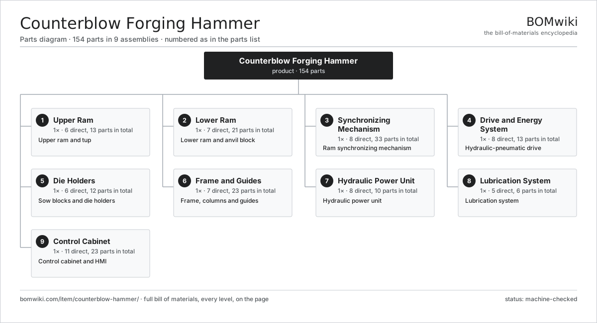
| # | Part | Qty | What it does |
|---|---|---|---|
| 1 | Upper Ram 6 parts | 1× | Upper ram and tup |
| 2 | Lower Ram 7 parts | 1× | Lower ram and anvil block |
| 3 | Synchronizing Mechanism 8 parts | 1× | Ram synchronizing mechanism |
| 4 | Drive and Energy System 8 parts | 1× | Hydraulic-pneumatic drive |
| 5 | Die Holders 6 parts | 1× | Sow blocks and die holders |
| 6 | Frame and Guides 7 parts | 1× | Frame, columns and guides |
| 7 | Hydraulic Power Unit 8 parts | 1× | Hydraulic power unit |
| 8 | Lubrication System 5 parts | 1× | Lubrication system |
| 9 | Control Cabinet 11 parts | 1× | Control cabinet and HMI |
3D model
No 3D model yet. Have a CAD file of this? Add a 3D model — STL renders right on this page; STEP, FreeCAD, and OpenSCAD sources are welcome too (openly licensed, like all 3D models on BOMwiki).
Build & assembly graph
expand / collapse · shared sub-assemblies converge · links to related products · est. labourTap an assembly to expand/collapse · tap a part to open it · use “Open page” for any node · drag to pan, scroll to zoom.
Bill of materials for Counterblow Forging Hammer
9 top-level lines · 75 rows shown · 154 parts total · indented to 3 levels| # | Item / sub-assembly | Part no. | Qty/assy | Ext. qty | Parts | Type |
|---|---|---|---|---|---|---|
| 1 | Upper Ram 6 parts | counterblow-hammer-upper-ram | 1× | 1 | 13 | assembly |
| 1.1 | Upper Ram Body | counterblow-hammer-upper-ram-body | 1× | 1 | · | part |
| 1.2 | Working Piston Rod | counterblow-hammer-upper-piston-rod | 1× | 1 | · | part |
| 1.3 | Ram Guide Gib | counterblow-hammer-ram-gib | 4× | 4 | · | part |
| 1.4 | Bronze Wear Plate | counterblow-hammer-ram-wear-plate | 4× | 4 | · | part |
| 1.5 | Cushion Ring | counterblow-hammer-cushion-ring | 2× | 2 | · | part |
| 1.6 | Fastener Set | fastener-set | 1× | 1 | · | part |
| 2 | Lower Ram 7 parts | counterblow-hammer-lower-ram | 1× | 1 | 21 | assembly |
| 2.1 | Lower Ram Body | counterblow-hammer-lower-ram-body | 1× | 1 | · | part |
| 2.2 | Lower Anvil Block | counterblow-hammer-lower-anvil-block | 1× | 1 | · | part |
| 2.3 | Lift Cylinder | counterblow-hammer-lift-cylinder | 2× | 2 | · | part |
| 2.4 | Ram Guide Gib | counterblow-hammer-ram-gib | 4× | 4 | · | part |
| 2.5 | Bronze Wear Plate | counterblow-hammer-ram-wear-plate | 4× | 4 | · | part |
| 2.6 | Vibration Mount | counterblow-hammer-vibration-mount | 8× | 8 | · | part |
| 2.7 | Fastener Set | fastener-set | 1× | 1 | · | part |
| 3 | Synchronizing Mechanism 8 parts | counterblow-hammer-sync-mechanism | 1× | 1 | 33 | assembly |
| 3.1 | Synchronizing Band | counterblow-hammer-sync-band | 4× | 4 | · | part |
| 3.2 | Band Pulley | counterblow-hammer-band-pulley | 4× | 4 | · | part |
| 3.3 | Band Clamp | counterblow-hammer-band-clamp | 8× | 8 | · | part |
| 3.4 | Coupling Cylinder | counterblow-hammer-sync-cylinder | 2× | 2 | · | part |
| 3.5 | Balance Valve | counterblow-hammer-balance-valve | 1× | 1 | · | part |
| 3.6 | Ball Bearing | ball-bearing | 8× | 8 | · | part |
| 3.7 | Oil Seal | oil-seal | 4× | 4 | · | part |
| 3.8 | Pressure Sensor | pressure-sensor | 2× | 2 | · | part |
| 4 | Drive and Energy System 8 parts | counterblow-hammer-drive-system | 1× | 1 | 13 | assembly |
| 4.1 | Working Cylinder | counterblow-hammer-working-cylinder | 1× | 1 | · | part |
| 4.2 | Drive Piston | counterblow-hammer-drive-piston | 1× | 1 | · | part |
| 4.3 | Hydropneumatic Accumulator | counterblow-hammer-accumulator | 2× | 2 | · | part |
| 4.4 | Nitrogen Bottle | counterblow-hammer-gas-bottle | 4× | 4 | · | part |
| 4.5 | Blow Valve | counterblow-hammer-blow-valve | 1× | 1 | · | part |
| 4.6 | Stroke Control Valve | counterblow-hammer-control-valve | 1× | 1 | · | part |
| 4.7 | O-Ring Set | oring-set | 1× | 1 | · | part |
| 4.8 | Pressure Sensor | pressure-sensor | 2× | 2 | · | part |
| 5 | Die Holders 6 parts | counterblow-hammer-die-holders | 1× | 1 | 12 | assembly |
| 5.1 | Upper Sow Block | counterblow-hammer-upper-sow-block | 1× | 1 | · | part |
| 5.2 | Lower Sow Block | counterblow-hammer-lower-sow-block | 1× | 1 | · | part |
| 5.3 | Upper Forging Die | counterblow-hammer-upper-die | 1× | 1 | · | part |
| 5.4 | Lower Forging Die | counterblow-hammer-lower-die | 1× | 1 | · | part |
| 5.5 | Die Locating Key | counterblow-hammer-die-key | 4× | 4 | · | part |
| 5.6 | Die Clamp Wedge | counterblow-hammer-die-wedge | 4× | 4 | · | part |
| 6 | Frame and Guides 7 parts | counterblow-hammer-frame | 1× | 1 | 23 | assembly |
| 6.1 | Frame Column | counterblow-hammer-column | 2× | 2 | · | part |
| 6.2 | Head Crown | counterblow-hammer-head-crown | 1× | 1 | · | part |
| 6.3 | Tie Rod | counterblow-hammer-tie-rod | 4× | 4 | · | part |
| 6.4 | Guide Liner | counterblow-hammer-guide-liner | 8× | 8 | · | part |
| 6.5 | Base Plate | counterblow-hammer-base-plate | 1× | 1 | · | part |
| 6.6 | Sheet Metal Panel | sheet-panel | 6× | 6 | · | part |
| 6.7 | Fastener Set | fastener-set | 1× | 1 | · | part |
| 7 | Hydraulic Power Unit 8 parts | counterblow-hammer-hpu | 1× | 1 | 10 | assembly |
| 7.1 | Charge Pump | counterblow-hammer-charge-pump | 2× | 2 | · | part |
| 7.2 | Oil Reservoir | counterblow-hammer-hyd-tank | 1× | 1 | · | part |
| 7.3 | Valve Manifold | counterblow-hammer-hyd-manifold | 1× | 1 | · | part |
| 7.4 | Filter Unit | counterblow-hammer-filter-unit | 1× | 1 | · | part |
| 7.5 | Oil Cooler | counterblow-hammer-oil-cooler | 1× | 1 | · | part |
| 7.6 | Coolant Pump | coolant-pump | 1× | 1 | · | part |
| 7.7 | Pressure Sensor | pressure-sensor | 2× | 2 | · | part |
| 7.8 | O-Ring Set | oring-set | 1× | 1 | · | part |
| 8 | Lubrication System 5 parts | counterblow-hammer-lubrication | 1× | 1 | 6 | assembly |
| 8.1 | Die Sprayer | counterblow-hammer-die-sprayer | 2× | 2 | · | part |
| 8.2 | Spray Pump | counterblow-hammer-spray-pump | 1× | 1 | · | part |
| 8.3 | Lubricant Tank | counterblow-hammer-lube-tank | 1× | 1 | · | part |
| 8.4 | Guide Grease Unit | counterblow-hammer-grease-unit | 1× | 1 | · | part |
| 8.5 | Pressure Sensor | pressure-sensor | 1× | 1 | · | part |
| 9 | Control Cabinet 11 parts | counterblow-hammer-controls | 1× | 1 | 23 | assembly |
| 9.1 | PLC Control | counterblow-hammer-plc | 1× | 1 | · | part |
| 9.2 | Operator HMI | counterblow-hammer-hmi | 1× | 1 | · | part |
| 9.3 | Blow Energy Controller | counterblow-hammer-blow-controller | 1× | 1 | · | part |
| 9.4 | Power Supply | power-supply | 1× | 1 | · | part |
| 9.5 | Relay | relay | 6× | 6 | · | part |
| 9.6 | Bare PCB | pcb-bare | 1× | 1 | · | part |
| 9.7 | Microcontroller | mcu | 1× | 1 | · | part |
| 9.8 | SMD Passive (R/C/L) | smd-passives | 1× | 1 | · | part |
| 9.9 | Connector | connector | 8× | 8 | · | part |
| 9.10 | Wire Bundle | wire-bundle | 1× | 1 | · | part |
| 9.11 | LCD Panel | lcd-panel | 1× | 1 | · | part |
Related products
same domain, ranked by shared parts Radial Forging Machine
288 parts · shares 4 with this page
Radial Forging Machine
288 parts · shares 4 with this page
 Rotary-Table Surface Grinder
172 parts · shares 4 with this page
Spline Rolling Machine
138 parts · shares 4 with this page
Rotary-Table Surface Grinder
172 parts · shares 4 with this page
Spline Rolling Machine
138 parts · shares 4 with this page
 CNC Lathe
511 parts · shares 3 with this page
Double-Disc Grinder
153 parts · shares 3 with this page
CNC Lathe
511 parts · shares 3 with this page
Double-Disc Grinder
153 parts · shares 3 with this page
 Swiss-Type CNC Lathe
301 parts · shares 3 with this page
Swiss-Type CNC Lathe
301 parts · shares 3 with this page
Sourcing: possible vendors
Prices, MOQ, and lead times are algorithmic estimates, not quotes, and not claims about these companies. Company mappings are curated by keyword; est. price band $10k–$1M. How estimates work| Vendor | HQ | Specialty | MOQ | Lead time |
|---|---|---|---|---|
|
🇩🇪DMG MORI
dmgmori.com ↗
|
Bielefeld, DE | Machine tools | 5 units | 12–20 wks |
|
🇯🇵Mazak
mazak.com ↗
|
Oguchi, JP | Machine tools | 5 units | 12–20 wks |
| haascnc.com ↗ | Oxnard, US | CNC machine tools | 5 units | 12–20 wks |
|
🇯🇵Okuma
okuma.com ↗
|
Niwa, JP | Machine tools | 5 units | 12–20 wks |
|
🇩🇪Trumpf
trumpf.com ↗
|
Ditzingen, DE | Laser & sheet-metal machines | 5 units | 12–20 wks |
1,040-word article