Friction Stir Welding Machine
ProductOverview
A friction stir welding machine joins metal without melting it. A rotating, non-consumable tool is plunged into the seam between two clamped parts and traversed along it; the friction of the tool against the metal heats it to a soft, plastic state below the melting point, and the tool stirs that softened metal from both sides together into a single solid joint behind it. Because the metal never becomes fully liquid, the weld avoids the porosity, solidification cracking, and alloy changes that plague fusion welding of aluminium, and it distorts far less. Friction stir welding produces strong, clean, repeatable joints in aluminium and other soft metals, which is why it is used for aircraft panels, rail car bodies, ship extrusions, and the large aluminium trays that hold electric-vehicle battery packs.
The machine resembles a very stiff milling machine. A heavy Machine Bed and a Gantry and Axes carry a Welding Spindle that turns the Stir Tool along the joint, while a Backing Fixture clamps the parts and a Force Control Axis axis holds the tool down with a controlled force. The CNC and Drives runs the whole sequence, and a Spindle Cooling system keeps the spindle stable.
How the joint forms
The Stir Tool does two jobs at once through its two features. The broad Tool Shoulder rubs on the surface and generates most of the heat, while also containing the softened metal so it cannot escape upward. The Tool Pin reaches down into the joint and, as the tool advances, sweeps plasticised metal from the front of the pin around to the back, where it consolidates under the shoulder into a solid weld. Nothing melts; the metal is forged and stirred while hot and soft. This solid-state nature is the whole point, because aluminium welded by melting tends to trap gas and crack, whereas a stir weld comes out dense and fine-grained, often stronger than a fusion weld in the same alloy.
The stiff structure
Friction stir welding pushes hard. The tool must be forced down with several tonnes and dragged sideways along the joint, all while the structure holds the tool position to a fraction of a millimetre. That is why the Machine Bed is a heavy Bed Casting and the Gantry and Axes is built like a machine tool, with Gantry Column uprights and a stiff Crossbeam. Each Linear Axis uses a Ball Screw and Linear Guide Rail rails driven by a Servo Motor, with a Linear Scale for accuracy. Any flex in this structure would let the tool wander off the seam or lift out of the plate, so stiffness drives the whole design.
Spindle and tooling
The Welding Spindle must deliver high torque at modest speed and survive heavy combined loads. Its Spindle Shaft runs in Spindle Bearing sets sized for the side and plunge forces, driven by a Spindle Motor and carrying the Tool Holder. The Stir Tool itself is made of a tool steel or, for harder metals, a more exotic material, because it sees high temperature and wear, though it is not consumed into the weld the way a wire or rod would be. Tool design, the shoulder profile and the pin shape, governs heat input and how well the metal mixes.
Clamping and force control
Two things keep a stir weld sound: the parts must not move, and the tool force must stay constant. The Backing Fixture handles the first, pressing the parts onto a hard Backing Anvil with Hold-Down Clamp elements and stopping them spreading with Side Rail members, all driven by Clamp Cylinder actuators. The Force Control Axis axis handles the second: rather than holding a fixed depth, it holds a target downward force using a Load Cell in a closed loop, so as the plate thickness or temperature varies the tool digs in or eases off to keep the heat and mixing right. Force control is what makes the process robust enough for production.
Control and use
The CNC and Drives ties it together, running the weld path with its CNC Board, powering the axes through Servo Drive units and the spindle through the Spindle Drive, and holding the force loop throughout. The Spindle Cooling system, with its Chiller, keeps the spindle and bearings at a steady temperature so the force readings stay true. Friction stir welding is the method of choice for long, straight or contoured joints in aluminium extrusions and plate: aircraft fuselage and wing panels, high-speed train bodies, ship deck panels, and battery enclosures. Its limits are that it suits flat and gently curved joints reachable by the tool more than complex three-dimensional ones, that it leaves an exit hole where the pin withdraws unless a retractable-pin tool is used, and that it needs the heavy, rigid machine described here rather than a portable torch.
Friction Stir Welding Machine parts and their functions
8 top-level parts · 351 parts in total · full bill of materials below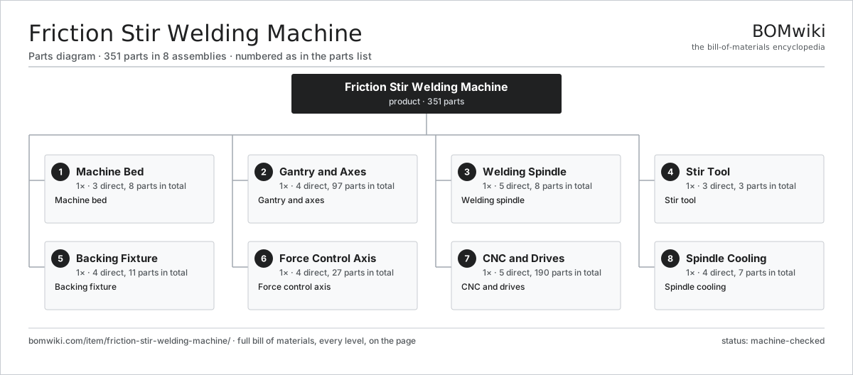
| # | Part | Qty | What it does |
|---|---|---|---|
| 1 | Machine Bed 3 parts | 1× | Machine bed |
| 2 | Gantry and Axes 4 parts | 1× | Gantry and axes |
| 3 | Welding Spindle 5 parts | 1× | Welding spindle |
| 4 | Stir Tool 3 parts | 1× | Stir tool |
| 5 | Backing Fixture 4 parts | 1× | Backing fixture |
| 6 | Force Control Axis 4 parts | 1× | Force control axis |
| 7 | CNC and Drives 5 parts | 1× | CNC and drives |
| 8 | Spindle Cooling 4 parts | 1× | Spindle cooling |
3D model
No 3D model yet. Have a CAD file of this? Add a 3D model — STL renders right on this page; STEP, FreeCAD, and OpenSCAD sources are welcome too (openly licensed, like all 3D models on BOMwiki).
Build & assembly graph
expand / collapse · shared sub-assemblies converge · links to related products · est. labourTap an assembly to expand/collapse · tap a part to open it · use “Open page” for any node · drag to pan, scroll to zoom.
Bill of materials for Friction Stir Welding Machine
8 top-level lines · 60 rows shown · 351 parts total · indented to 3 levels| # | Item / sub-assembly | Part no. | Qty/assy | Ext. qty | Parts | Type |
|---|---|---|---|---|---|---|
| 1 | Machine Bed 3 parts | friction-stir-welding-machine-bed | 1× | 1 | 8 | assembly |
| 1.1 | Bed Casting | friction-stir-welding-machine-bed-casting | 1× | 1 | · | part |
| 1.2 | T-Slot Table | friction-stir-welding-machine-t-slot-table | 1× | 1 | · | part |
| 1.3 | Levelling Mount | friction-stir-welding-machine-levelling-mount | 6× | 6 | · | part |
| 2 | Gantry and Axes 4 parts | friction-stir-welding-machine-gantry | 1× | 1 | 97 | assembly |
| 2.1 | Gantry Column | friction-stir-welding-machine-column | 2× | 2 | · | part |
| 2.2 | Crossbeam | friction-stir-welding-machine-crossbeam | 1× | 1 | · | part |
| 2.3 | Linear Axis 5 parts | friction-stir-welding-machine-axis | 3× | 3 | 30 | assembly |
| 2.3.1 | Ball Screw | ball-screw | 1× | 3 | · | part |
| 2.3.2 | Linear Guide Rail | linear-guide | 2× | 6 | · | part |
| 2.3.3 | Servo Motor 4 parts + deeper › | servo-motor | 1× | 3 | 24 | assembly |
| 2.3.4 | Ball Bearing | ball-bearing | 2× | 6 | · | part |
| 2.3.5 | Linear Scale | friction-stir-welding-machine-axis-encoder | 1× | 3 | · | part |
| 2.4 | Way Cover | friction-stir-welding-machine-way-cover | 4× | 4 | · | part |
| 3 | Welding Spindle 5 parts | friction-stir-welding-machine-spindle | 1× | 1 | 8 | assembly |
| 3.1 | Spindle Motor | friction-stir-welding-machine-spindle-motor | 1× | 1 | · | part |
| 3.2 | Spindle Shaft | friction-stir-welding-machine-spindle-shaft | 1× | 1 | · | part |
| 3.3 | Spindle Bearing | friction-stir-welding-machine-spindle-bearing | 4× | 4 | · | part |
| 3.4 | Tool Holder | friction-stir-welding-machine-tool-holder | 1× | 1 | · | part |
| 3.5 | Spindle Housing | friction-stir-welding-machine-spindle-housing | 1× | 1 | · | part |
| 4 | Stir Tool 3 parts | friction-stir-welding-machine-tool | 1× | 1 | 3 | assembly |
| 4.1 | Tool Shoulder | friction-stir-welding-machine-tool-shoulder | 1× | 1 | · | part |
| 4.2 | Tool Pin | friction-stir-welding-machine-tool-pin | 1× | 1 | · | part |
| 4.3 | Tool Shank | friction-stir-welding-machine-tool-shank | 1× | 1 | · | part |
| 5 | Backing Fixture 4 parts | friction-stir-welding-machine-fixture | 1× | 1 | 11 | assembly |
| 5.1 | Backing Anvil | friction-stir-welding-machine-backing-bar | 1× | 1 | · | part |
| 5.2 | Hold-Down Clamp | friction-stir-welding-machine-clamp | 4× | 4 | · | part |
| 5.3 | Side Rail | friction-stir-welding-machine-side-rail | 2× | 2 | · | part |
| 5.4 | Clamp Cylinder | friction-stir-welding-machine-clamp-cylinder | 4× | 4 | · | part |
| 6 | Force Control Axis 4 parts | friction-stir-welding-machine-force-control | 1× | 1 | 27 | assembly |
| 6.1 | Plunge Actuator | friction-stir-welding-machine-z-actuator | 1× | 1 | · | part |
| 6.2 | Load Cell | friction-stir-welding-machine-load-cell | 1× | 1 | · | part |
| 6.3 | Ball Screw | ball-screw | 1× | 1 | · | part |
| 6.4 | Servo Motor 4 parts | servo-motor | 1× | 1 | 24 | assembly |
| 6.4.1 | Stator Assembly 3 parts + deeper › | stator-assembly | 1× | 1 | 3 | assembly |
| 6.4.2 | Rotor Assembly 4 parts + deeper › | rotor-assembly | 1× | 1 | 19 | assembly |
| 6.4.3 | Encoder | encoder | 1× | 1 | · | part |
| 6.4.4 | Motor Housing | motor-housing | 1× | 1 | · | part |
| 7 | CNC and Drives 5 parts | friction-stir-welding-machine-cnc | 1× | 1 | 190 | assembly |
| 7.1 | CNC Board 3 parts | friction-stir-welding-machine-cnc-board | 1× | 1 | 162 | assembly |
| 7.1.1 | Bare PCB | pcb-bare | 1× | 1 | · | part |
| 7.1.2 | Microcontroller | mcu | 1× | 1 | · | part |
| 7.1.3 | SMD Passive (R/C/L) | smd-passives | 160× | 160 | · | part |
| 7.2 | Servo Drive 4 parts | friction-stir-welding-machine-servo-drive | 4× | 4 | 5 | assembly |
| 7.2.1 | Bare PCB | pcb-bare | 1× | 4 | · | part |
| 7.2.2 | IGBT Power Module | igbt-module | 1× | 4 | · | part |
| 7.2.3 | Gate Driver IC | gate-driver-ic | 1× | 4 | · | part |
| 7.2.4 | DC-Link Capacitor | dc-link-cap | 2× | 8 | · | part |
| 7.3 | Spindle Drive 4 parts | friction-stir-welding-machine-spindle-drive | 1× | 1 | 6 | assembly |
| 7.3.1 | Bare PCB | pcb-bare | 1× | 1 | · | part |
| 7.3.2 | IGBT Power Module | igbt-module | 1× | 1 | · | part |
| 7.3.3 | Gate Driver IC | gate-driver-ic | 1× | 1 | · | part |
| 7.3.4 | DC-Link Capacitor | dc-link-cap | 3× | 3 | · | part |
| 7.4 | LCD Panel | lcd-panel | 1× | 1 | · | part |
| 7.5 | Power Supply | power-supply | 1× | 1 | · | part |
| 8 | Spindle Cooling 4 parts | friction-stir-welding-machine-cooling | 1× | 1 | 7 | assembly |
| 8.1 | Chiller | friction-stir-welding-machine-chiller | 1× | 1 | · | part |
| 8.2 | Coolant Pump | friction-stir-welding-machine-coolant-pump | 1× | 1 | · | part |
| 8.3 | Coolant Hose | friction-stir-welding-machine-coolant-hose | 4× | 4 | · | part |
| 8.4 | Flow Switch | friction-stir-welding-machine-flow-switch | 1× | 1 | · | part |
Related products
same domain, ranked by shared parts Compression Spring Coiler
1,167 parts · shares 7 with this page
Spring End Grinding Machine
1,048 parts · shares 7 with this page
Compression Spring Coiler
1,167 parts · shares 7 with this page
Spring End Grinding Machine
1,048 parts · shares 7 with this page
 Torsion Spring Coiler
1,148 parts · shares 7 with this page
Torsion Spring Coiler
1,148 parts · shares 7 with this page
Sourcing: possible vendors
Prices, MOQ, and lead times are algorithmic estimates, not quotes, and not claims about these companies. Company mappings are curated by keyword; est. price band $10k–$1M. How estimates work| Vendor | HQ | Specialty | MOQ | Lead time |
|---|---|---|---|---|
|
🇩🇪DMG MORI
dmgmori.com ↗
|
Bielefeld, DE | Machine tools | 5 units | 12–20 wks |
|
🇯🇵Mazak
mazak.com ↗
|
Oguchi, JP | Machine tools | 5 units | 12–20 wks |
| haascnc.com ↗ | Oxnard, US | CNC machine tools | 5 units | 12–20 wks |
|
🇯🇵Okuma
okuma.com ↗
|
Niwa, JP | Machine tools | 5 units | 12–20 wks |
|
🇩🇪Trumpf
trumpf.com ↗
|
Ditzingen, DE | Laser & sheet-metal machines | 5 units | 12–20 wks |
931-word article